Abstract
The understanding of areas for “classical” electrochemistry (including catalysis, electrolysis and sensing) and bio‐electrochemistry at the micro/nanoscale are focus on the continued performance facilitations or the exploration of new features. In the recent 20 years, a different mode for driving electrochemistry has been proposed, which is called as bipolar electrochemistry (BPE). BPE has garnered attention owing to the interesting properties: (i) its wireless nature facilitates electrochemical sensing and high throughput analysis; (ii) the gradient potential distribution on the electrodes surface is a useful tool for preparing gradient surfaces and materials. These permit BPE to be used for modification and analytical applications on a micro/nanoscale surface. This review aims to introduce the principle and classification of BPE and BPE at micro/nanoscale; sort out its applications in electrocatalysis, electrosynthesis, electrophoresis, power supply and so on; explain the confined BPE and summarize its analytical application for single entities (single cells, single particles and single molecules), and discuss finally the important direction of micro/nanoscale BPE.
Keywords: micro/nano-electrochemistry, micro/nanoscale bipolar electrochemistry, wireless nature, gradient potential distribution, analytical application for single entities
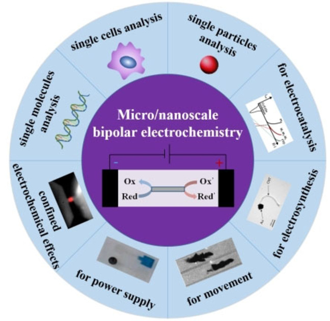
The review aims to introduce the principle and classification of BPE and BPE at micro/nanoscale; sort out its applications in electrocatalysis, electrosynthesis, electrophoresis and power supply; explain the confined BPE and summarize its analytical application for single entities (single cells, single particles and single molecules), and discuss finally the important direction of micro/nanoscale bipolar electrochemistry.
1. Introduction
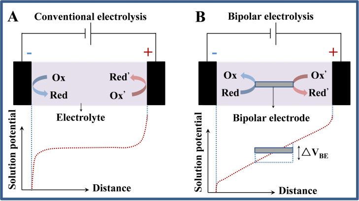
Bipolar electrochemistry (BPE) is a well‐established wireless technique in virtue of the faradic reactions at the two poles of a conductive object polarized in a electric field. [1] The usual setup for BPE contains a pair of feeder electrodes physically connected with the both ends of a power supply and a conductive object (called as bipolar electrode) embedded in between the feeder electrodes, as shown in Figure 1b. The sensing mechanism of BPE is quite different from that of conventional electrochemistry. In a conventional electrolytic system containing supporting electrolytes with a high concentration, a voltage applied between two electrodes could make ions accumulated and electrical double layers were generated at the electrode/solution interfaces. If the applied potentials are enough high, the obviously steep electric fields generated at the surface of the electrodes will activate redox reactions at the anodic and cathodic poles (Figure 1A). [2] Relatively, in a supporting electrolyte with low concentration, an electric field instead of electrical double layers creates in the solution. In this case, redox reactions is not easily generated on the electrode surfaces; however, a conductive object placed between the electrodes can act as a bipolar electrode and initiate both oxidation and reduction at their poles (Figure 1B), [3] and the concept of BPE was born.
Figure 1.
Comparison of electrolytic systems for (A) conventional and (B) bipolar electrolysis.
Although the phenomenon of BPE has been known for ages, it has never crossed the frontier of several industrial field developed in the 1970s. [4] In the last two decades, BPE seems to come back to life, revealing remarkable properties in the field of material science and bioanalysis, especially in submicron‐scale surface modification and sensing in micro/nanoscale systems. [5] However, the traditional research object of BPE is usually a macroscopical electrode interface containing millions or more single entities, and the results reflect the overall average performance of all entities in the system. Due to the intrinsic and significant differences in the structure, properties and activity between individual entities, the average effect will obscure the relationship between entity and function, which is not conducive to the elucidation of the mechanism of interface electron transfer and the improvement of its performance. Therefore, the understanding of fields for classical electrochemistry and bio‐electrochemistry at the micro/nanoscale BPE are critical to continued performance facilitations or the exploration of new features.
Limiting electrochemical systems to micro/nanoscales offers many advantages, including improved reaction rates and faster reaction times on account of shorter mass transfer time scales. [6] In addition, the restricted systems are beneficial for analytical applications because they require smaller sizes and are well suited for process parallelization. [7] However, a restriction of classic BPE is related to the radial length of the conductive object: the shorter the length of the conductive object, the larger the applied potential required to respectively induce redox reactions at its poles. [8] This become an important limitation for micro/nanoscale objects. They are difficult to polarize with BPE because excessively potentials are required, on the order of tens of kilovolts (kV) or more, [9] which will restrict its application and development.
Some recent studies have successfully exhibited a spatial confined effect occurred at micro/nanopores. The spatial confinement of voltage drop in these pores causes a locally enhanced polarization of a bipolar electrode. [10] A crucial point can be distilled from these reports: the asymmetric polarization could polarize micro/nanoscale objects at a much lower voltage in this spatial restriction than a classic BPE setup, which promote the micro/nanoscale BPE in electrochemical measurement at the single entities, including single cells, single particles and single molecules. The research methods and theoretical models also began to deepen the single entity levels, establish and develop electrochemical in situ on micrometers and even nanoscale interfaces. This review will summarize the principles and the applications of BPE in micro/nanoscale analysis, the confined enhancement effect based BPE and its applications at the single entities.
2. Principle and Classification of BPE
Unlike traditional three‐electrode systems where electrodes are connected by wires, in bipolar electrochemical systems, the bipolar electrodes used to carry the electrochemical reaction are free, with no wires connected directly with the power supply. It generally placing the (semi)conductor in a solution that generates an electric field between the two feeder electrodes. According to electrostatic field theory, the bipolar electrode is an equipotential body with the same potential points, the uneven potential presented in the surrounding solution will cause a gradient potential distribution between the electrolyte and electrode, which varies along the principal axis parallel to the electric field lines, as shown in Figure 1B. This results in one end of the electrode prioritizing the area of the oxidation process, while a reduction reaction will occur at the other end. Therefore, BPE produces a gradient potential distribution and asymmetrical reactions on the surface of the electrode, constituting a method of breaking the symmetry of the electrochemical system. In addition, there are no special restrictions on the shape of the bipolar electrode and multiple electrode groups can react simultaneously.
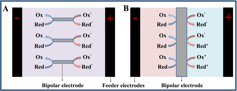
Bipolar electrochemical systems are divided into two types, one is “open” BPE and the other is “closed” BPE. Figure 2A shows an open bipolar electrochemical system in which current can pass through both the bipolar electrode and the electrolyte. [11] Whereas in a closed BPE device, the solutions immersing the anode and cathode of bipolar electrode are spatially isolated from each other, and the only current channel between the two half chambers is a bipolar electrode (Figure 2B). Duval et al. [12] reported the direct relationship between the polarization potential difference at the bipolar electrode (ΔVBE) and the strength of resultant electric field (ΔVFE/d, where ΔVFE is the potential difference applied between the two feeder electrodes and d is the distance between both feeder electrodes) in a typical “open” BPE configuration as described by Equation 1:
| (1) |
Figure 2.
Schematic of (A) the open and (B) closed BPE configuration.
Where L is the length of the conductor. It can be inferred that the potential difference generated on a conductor is relied on its size. This means that the smaller the conductor (L), the larger the applied electric field (ΔVFE/d) must be. Therefore, if d is 1.0 m, to induce a BPE on micro/nanoscale conductors requires voltages of tens of kV or more, which are difficult to operate.
Differs from the ‘‘open’’ configuration, the ‘‘closed’’ BPE has several unique features. First, the fact that no by‐pass current exists is very advantageous, especially in areas where high efficiency is required. Secondly, compared with the “open” structure, both the polarization potential difference at both ends of the bipolar electrode and the applied potential difference at the feeder electrodes can significantly increase by changing the material [13] or geometry of the bipolar electrode and other parameters. [14] Finally, the cell is divided into two separate compartments, and this closed structure could be used to physically separate bipolar reduction mixtures from oxidation mixtures if isolation of reaction products or reactants is required. These properties of closed BPE and its geometric structure make it increasingly widely used in sensing, catalysis, screening and other fields. [15]
3. BPE at Micro/Nanoscale
BPE allows different reactions to occur simultaneously at different locations of the object. Therefore, it is probable to design complexes with different functions and study separate reactions at the micro/nanoscale. The primary advantage stems from its wireless nature, the gradient potential distribution and electro‐neutrality along the bipolar electrode, allowing for spatially selective modifications. Because topologically selective modifications at these scales are difficult to process and conventional chemical techniques are less efficient, BPE is a potential approach to fabricate selectively modified micro/nanoscale complexes and researching different electrochemical reactions.
3.1. The electrocatalysis actuated by BPE
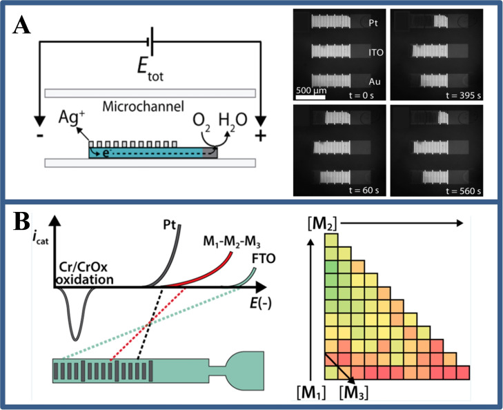
In BPE system, there is a fact that the anodic and cathodic reaction rates on a bipolar electrode must be equal. [16] This means that the electrochemical reaction of interest (i. e., catalysis) at one pole of the bipolar electrode can be revealed by the electrochemical reaction at the other pole. For example, Fosdick et al. [17] reported a rapid and efficient screening of electrocatalyst candidates based on the electrocatalytic effect of microscale bipolar electrode array. The approach is based on simultaneous activation of the redox reaction and the electro‐dissolution of Ag at the cathode and anode, respectively. Because the electrochemical reaction rate of the two poles is coincident, the degree of Ag electro‐dissolution at the anode is directly relevant with the oxygen reduction reaction at the cathode. After the electrochemical experiment, the screening results could be evaluated by simple optical imaging (Figure 3A). On this basis, the group [18] also designed a BPE microarray for screening and evaluating the hydrogen evolution capability of catalysts. The key point from these studies is that abundant catalyst groups could be screened in a short time (a few minutes) using simple instruments, and that the BPE screening method can leave a permanent record (Figure 3B).
Figure 3.
(A) Schematic illustration of electrocatalyst candidates based on the electrocatalytic effect of microscale bipolar electrode array, and the optical micrograph of electrode before and after applying voltage at different times. Reproduced with permission from Ref. [17]. Copyright 2012, American Chemical Society; (B) Schematic of the relationship between the voltages required to drive both Cr electrooxidation and the HER, and the matrix plot showing the number of dissolved Cr bands in bimetallic and trimetallic catalysts as a function of composition. Reproduced with permission from Ref. [18]. Copyright 2014, American Chemical Society.
3.2. The electrosynthesis controlled by BPE
Shannon and co‐workers reported the electrosynthesis of Cd and CdS on an electrode. [19] An Au wire electrode as a bipolar electrode was placed in a cocktail aqueous solution containing Cd and S sources under the application of an external electric field. Using bipolar electrochemical wireless nature and the gradient potential distribution, the reduced materials on the Au wire electrode are respectively Cd enriched CdS (silver/gray), CdS (orange) and S (yellow). The size of the employed bipolar electrode (Au wire) is 1.7 cm long and 1.0 mm diameter. If the size is smaller, it must face the application of potential of the order of several hundred kV, which causing practical defects including bubble generation, excessive ohmic heating and so on within the cell.
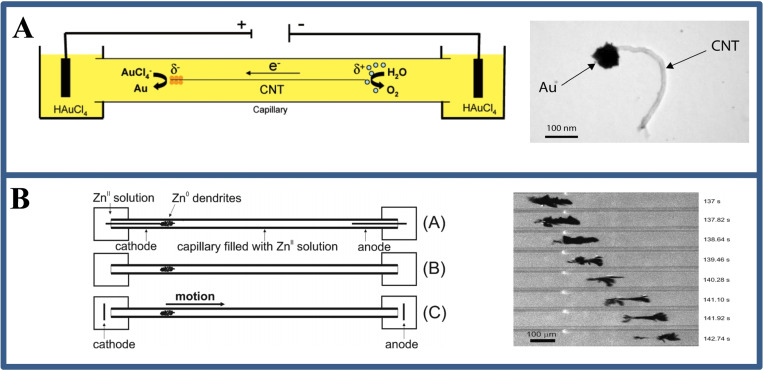
One solution is to perform BPE in a capillary electrophoresis (CE) device. The device for capillary‐assisted bipolar deposition (CABED) was a successful case to employ CE equipment for microscale bipolar deposition at the first time. [9b] The setup comprises a glass capillary filled with a solution dispersing carbon nanotubes and metal salts (Figure 4A). The end of the capillary is then placed in a compartment containing the drive electrode, which is connected to a high‐voltage power supply. When a voltage of ∼30 kV is applied, the resulting electric field causes an electrical seepage flow from the anode chamber to the cathode chamber. At this point, the carbon nanotubes (CNT) suspended in solution act as cathode electrodes, and as they move toward the cathode chamber, the water is oxidized at its anode, and gold ion (Au3+) is reduced to Au at its cathode, electrodepositing the Au nanoparticles at one end of the carbon nanotube (Figure 4A). Other metals, including copper and nickel, can also be electrosynthesis using the same method, and the latter composite is magnetic. Non‐metallic materials like conductive polymers can also be prepared with the CABED method.[ 9 , 20 ] For example, janus‐like objects are produced by oxidation of pyrrole at one end of a carbon nanotube to produce polypyrrole and reduction of copper ion at the other end.
Figure 4.
(A) The device diagram and TEM image of Au electrodeposition at one end of CNT by CABED method. Reproduced with permission from Ref. [9b]. Copyright 2008, American Chemical Society; (B) The device diagram and the optical image of zinc dendrite movement under BPE in zinc sulfate solution. Reproduced with permission from Ref. [22]. Copyright 2010, American Chemical Society.
The cooperation of electrophoresis and electrosynthesis in BPE would be an effective strategy to synthesize nanostructured materials. Some reports pointed that the introduction of metal ions electrophoresis in bipolar electrochemical systems could enhance the electrochemical reaction rate on the surface of the bipolar electrode, thus increase the mechanical strength of the synthesized nanomaterials. For example, Inagi and co‐workers [21] enhanced the migration rate of ionic species for templated electrodeposition with the help of the electrophoretic effect. By controlling the intensity of the applied electric field and enhancing the directional motion of charged ions in the electric field, successfully prepared a nanorod array that maintained high mechanical strength after the template was removed.
3.3. The movement of nanoconductor induced by BPE
The reduction of metals caused by BPE has been discussed above, the oxidation or corrosion may also occur at the anode of the bipolar electrode. [12a] Integrating these two phenomena in an ingenious method, the movement of zinc dendrites in a capillary could be observed (Figure 4B). [22] The evidence that this movement and morphologic evolution occurs in the opposite direction of electroosmotic flow suggests that this behavior is caused by BPE rather than electrophoresis, a similar phenomenon found by Bradley. [23] The deposition/dissolution mechanism on a silver nanoparticles (Ag NPs, 200 nm) was observed by coupling BPE in a submicron space. This dynamic bipolar self‐regeneration strategy can be used for wireless local deposition or surface patterning applications.
3.4. The power supply by BPE
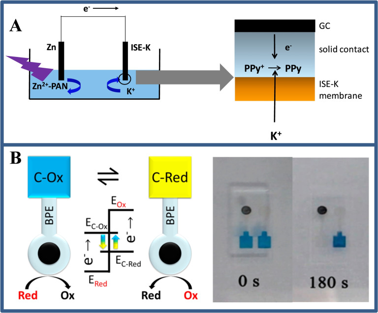
The point‐of‐need sensing applications motivate the development of techniques for powering a BPE system without the power supply. Over the past few years, several innovative approaches to generating driving voltages have been demonstrated, including the use of junction potentials, [24] self‐powered BPE, [25] cascaded BPE [26] and wireless energy transfer. [27] For example, small reverse electrodialysis patches junction potentials are generated and have been used for bipolar electrochemical powering. These patches were formed by the alternating stack of cation and anion exchange membranes, separating empty and K+ salt‐filled compartments (Figure 5A). The stack can be stored dry, and after wetting with water, generates a junction potential in response to a concentration gradient because of the different transport diffusion of ions across the membrane. [25b] In addition, Wang et al. [25a] designed a self‐powered BPE array in which paired spontaneous reactions appear when the standard reduction potential of reduction reactions is higher than that of oxidation reactions by a certain amount. The Prussian blue film was reduced and switched to colorless when coupled with the oxidation of glucose (Figure 5B). Although these methods are useful, their application is restricted because the junction potential can only reach appropriate voltages (hundreds of mV), and spontaneous BPE has stringent requirements on the reduction potential of sensing and reporting reactions. Besides concentration gradient, the pressure could also be an alternative driving force for BPE.
Figure 5.
(A) Scheme of the optical‐electrochemical system with ion‐selective membrane. Reproduced with permission from Ref. [25b]. Copyright 2018, Elsevier; (B) Schematic illustration on the self‐powered BPE strategy for the displaying analysis of catalytic redox reaction and photos of time‐dependent self‐powered‐BPE‐electrode for the ethanol electro‐oxidation. Reproduced with permission from Ref. [25a]. Copyright 2016, American Chemical Society.
Dumitrescu et al. [25c] demonstrated that the BPE reactions can proceed without external electrical power. Specifically, they found that a solution flowing through the micro‐channels can generate a flow potential of up to ∼8 V, which is sufficient for the Faradaic electrochemical reaction occurs on bipolar electrodes. Hence, low‐current devices may be self‐powered and therefore be used in emergency situations or areas of the world where electricity is not readily available.
4. Confined BPE
4.1. Confined effect of micro/nanoscale BPE
While the CABED setup allows for the simultaneous processing of thousands or even millions of nanoparticles in bulk solutions, it also has drawbacks. First, the used CE equipment is rather expensive. Essentially, the voltages as tens of kV still limit the application of BPE, especially in biological analysis. The confined electrochemistry has attracted extensive attention of researchers because of its enhanced effect on the polarization of electric charge, light and electric field. [28] The confined effect often endows materials or molecules with more novel chemical and physical properties and has great application prospects in the fields of optics, electronic devices and catalytic reactions. [29] Therefore, combining the confined effect with BPE may offer unprecedented analytical advantages.
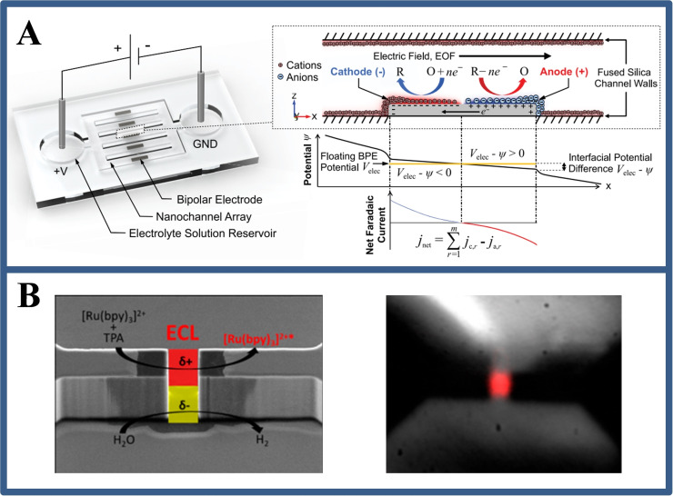
Geometries that confine ionic and molecular species to the nanoscale can dramatically alter physical transport phenomena when surface effects and charge‐shielding electric double layers become significant compared with the system size, as conventional macroscopic assumptions of electroneutrality and confinement currents break down. [30] For example, the structure of the electrical double layers directly affects the kinetics of electrochemical reactions. However, these effects are not properly treated in traditional macroscopic models. Eden et al. [31] present a systematic numerical model for a nano‐confined BPE system so far (Figure 6A). By observing the electrolysis reactions of water and the transports of ions and dissolved gases in the confined BPE system, they found that the reaction kinetics on the BPE dynamically transformed from the charge‐transfer‐limited to mass‐transfer‐limited time domain. This services a foundation for further understanding and development of the BPE mechanisms in a confined space.
Figure 6.
(A) Schematic of nanofluidic device containing a BPE array (left), and a picture of the electrodynamic and current‐voltage properties of the BPE surface (right). Reproduced with permission from Ref. [31]. Copyright 2019, American Chemical Society; (B) Schematic diagram of luminescent micropores with asymmetric redox reactions and luminescence images of their regions. Reproduced with permission from Ref. [10b]. Copyright 2019, American Chemical Society.
By confining BPE to micropores, Sojic's group [10b] showed the wireless polarization at much lower potentials than in a classic BPE (Figure 6B). This work found that the electric field strength is mainly concentrated in the solid micropores. Such a well designed structure allows achieving completely polarization to induce electrochemical reactions at a much lower potential (7 V) compared with the >240 V required in a traditional BPE device. This phenomenon is intrinsically related to the spatially confinement effect of micropores due to the sharp potential drop. This wireless electrochemiluminescence (ECL) micropore laid groundwork for ECL imaging analysis at single cells.
4.2. BPE triggered in nanocapillary electrode
Nanocapillary, prepared by a laser‐assisted pulling method, has become a burgeoning tool for various analytical fields due to the advantages of easy fabrication, small size and needle‐tip geometry. Modifying the pulled nanocapillary with different conductive layers (e. g., Pt, Au) can greatly expand their sensing capabilities. At present, nanocapillary electrodes have been successfully applied in the study of single cells, single particles and single molecules. However, to achieve the wireless BPE, it is necessary to ensure that the outer wall of the nanocapillary is free of conductive layers. At present, wireless nanocapillary electrode (WNE) can be prepared by two methods, one is by chemical reduction: the metal salt solution was directly filled into the nanocapillary and in situ chemical reduction was carried out with reducing agent until the tip of the nanocapillary was filled with reduced metal particles. For example, Au NPs were formed by reducing chlorauric acid in sodium borohydride solution. [32] Another method is to use vapor deposition (such as electron beam evaporation or magnetron sputtering) to uniformly deposit metal conductive layer on the inner and outer wall of the nanocapillary, and then use hydrochloric acid solution to remove the metal deposited on the outer wall of the capillary. [33] The WNE has become an effective substitute for traditional nanoelectrode, because it could induce a potential difference on the metal conductor at the tip of the capillary and achieves the analysis of the target molecules. This sensing approach generates redox reactions through ionic current rather than the metal wire transmission, which avoids background noise caused by the gap between metal wires and the inner wall of nanocapillary.
The WNE can be using for traditional electrochemical analyses such as cyclic voltammetry and amperometric methods to detect the redox activity of analytes. Zhang et al. [21] reported the voltammetric response of coupled electrochemical reactions on wireless micro/nano‐capillary electrodes in a closed bipolar chamber and understand its dependence on the concentration of redox species and electrode size. The work demonstrated that the voltammetric response at a wireless micro/nanoscale interface is quite different from that of conventional electrodes and the excellent capability of quantitative analysis using the bipolar characteristics of wireless microelectrodes.
5. Analytical Application for Single Entities
With the rapid development of modern science, the observation and study of life phenomena have reached the micro/nanoscale level including single cells, single particles and single molecules. How to obtain accurate (bio)chemical information in such a scale range is a serious challenges facing all fields of research in chemistry. Next, the main focus is on BPE under a micro/nanoscale to analyse these single entities (including single cells, single particles and single molecules) in recent years.
5.1. For single cells analysis
Single cells analysis is a key technology for studying cellular heterogeneity, which is of great significance for the study of biological processes and the development of new drugs. ECL is a branch of electrochemistry that uses light mode to reflect the speed of electron transfer at the electrode interface. [34] Applying ECL in BPE analysis yields a more intuitive wireless detection method. In 2001, Manz et al. [35] first coupled BPE and ECL (BPE‐ECL) to build a new type of detector that generates ECL signals by wireless sensing. However, BPE‐ECL has not been developed and broken until 2016. Xu′s group [36] used the BPE‐ECL system for the analysis of cell surface glycoproteins for the first time. They designed a U‐shaped indium tin oxide coated electrode and then separated the two ends with a straight pipe, one end is the cathode and the other end is the anode. When dissolved oxygen is reduced at the cathode, Ru(bpy)3 2+/TPrA is oxidized at the anode, resulting in ECL emission. In this design, a competitive strategy between ferrocene‐labeled target protein aptamers and target cancer cells was designed at the anode, and the quantification of target cell concentration was successfully achieved by using the quenching effect of ferrocene on ECL signaling. In addition, this open BPE‐ECL technology has also been applied to the detection of folic acid receptors in HL‐60 cell species. [37]
However, ECL luminophores (e. g., Ru(bpy)3 2+ and luminol) have biological toxicity, which could affect the detection biochemically analyze of living cells. The closed BPE could avoid this drawback. The closed device can use different solutions at the positive and negative ends, which physically separate the cells from the solution containing luminophores. Wu et al. [38] developed a closed BPE device to capture target cancer cells at the cathodic chamber and introduce Ru(bpy)3 2+/TPA‐ECL system at the anodic chamber. According to the principle of electric neutrality of bipolar electrode, the change of cathodic conductivity before and after capturing cancer cells is used to control the change of anodic ECL signal intensity, so as to successfully detect cancer cells. Not only that, the closed BPE‐ECL systems have also been reported for the detection of intracellular H2O2 [39] and the count of cancer cells. [40]
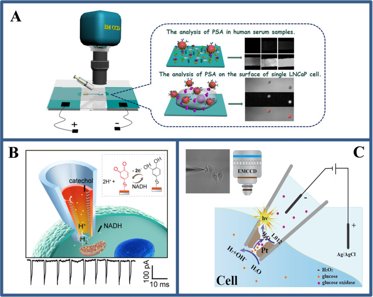
Although the BPE‐ECL strategy has been applied to cell analysis, it is based on the overall analysis of cell populations or a small number of cells and does not achieve detection at the single cells level. In 2018, our group [41] developed a versatile closed BPE‐ECL immune‐sensing platform for high‐throughput visualization analysis of prostate antigens on the surface of individual fixed cancer cells, as shown in Figure 7A. With the development of life, capturing real‐time biological information and molecular dynamics information in living cells are important for understanding signal pathways and cell communication. However, there is no usual approach to gain a wide range of redox active species at single living cells level with a resolution of cell compartment. Therefore, it is necessary to develop simple and efficient wireless sensing methods to realize the electrical analysis of molecules in living cells.
Figure 7.
(A) The BPE‐ECL device for single cell surface antigen analysis and schematic diagram its positive extreme analysis interface. Reproduced with permission from Ref. [41]. Copyright 2018, American Chemical Society; (B) Asymmetric WNE based BPE strategy for monitoring electrochemical reaction dynamics at single live cells. Reproduced with permission from Ref. [14]. Copyright 2012, American Chemical Society; (C) Schematic illustration of the WNE‐based BPE‐ECL strategy for imaging analysis of cytosol at single cells. Reproduced with permission from Ref. [42]. Copyright 2020, Wiley.
Long's group [14] demonstrated an WNE‐based asymmetric amplification mechanism for the real‐time monitoring of proton‐transmitting coenzyme used in cellular metabolism at single living cells (Figure 7B). Using a simple fabrication process, they fabricated an asymmetric WNE with a diameter of less than 90 nm. This asymmetric geometry enables over 90 % potential drop occur across the WNE, thereby transforming the Faradaic current response into an easily distinguishable bubble‐induced transient ionic current. Such asymmetric strategy makes the current signal to be amplified by at least 3 orders of magnitude, improving the current resolution from nA to pA, enabling real‐time monitoring of the respiratory chain in living cells and assessing the effect of anticancer drugs in single MCF‐7 cells.
Inspired by the sharp voltage drop in such confined nanopores, in our research, an open BPE device was developed by modifying the inner wall of the WNE with a platinum coating, achieving intracellular wireless ECL imaging, [42] as shown in Figure 7C. The synergetic effects of the WNE and BPE‐ECL result in the spatially confined voltage drop on the Pt deposit, which induces ECL emission at a voltage two orders of magnitude lower than classical BPE. The establishment of BPE‐ECL at the WNE in single cells will provide a case for the field of single‐cell electrochemical analysis. In addition, the barrier of the low throughput in single cells electrochemical analysis and of in situ electrochemical analysis for intracellular molecules were be broken down by utilizing the wireless properties of BPE at the micro/nanoscale by Jiang's group. [43]
5.2. For single particles analysis
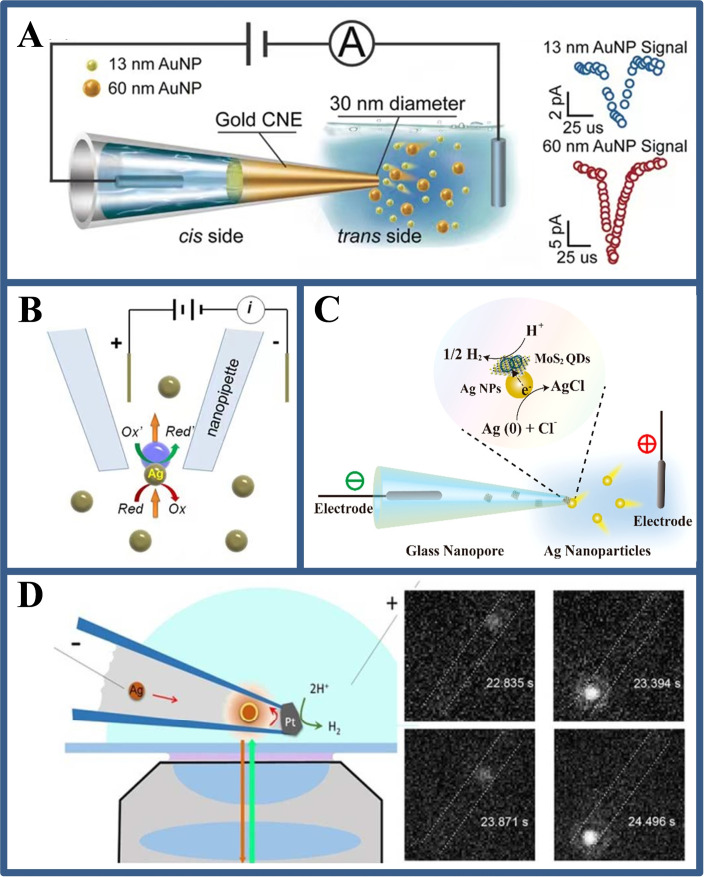
The study of single particles is important because the true systems are often heterogeneous such as nanoparticles of different sizes and shapes. If single particles are measured by a large electrode, the larger background noise caused may mask the signals of individual particles. Therefore, the nanoelectrodes with a micro/nanoscale size are applied to the field of single particles analysis. Long et al. [44] prepared a WNE with a diameter of 30 nm with a rapid electro‐driven chemical reduction method (Figure 8A). A capacitance‐based detection mechanism is employed to get a high current resolution (0.6 pA ±0.1 pA) and temporal resolution (0.01 ms). With the help of the electrochemical spatial confined effect, the microsecond‐scale collision process of individual NPs could be distinguished from its current traces, revealing the dynamic interactions between NPs and a nanocapillary. Han et al. [45] used bipolar electrochemical resistance pulse sensing to observe the translocation of Ag NPs (Figure 8B). The tip of nanocapillary is used to focus the applied voltage and activate the bipolar electrochemical reaction of nanoparticles, which reduces the noise caused by the previously applied high voltage. When the Ag NPs pass through the tip, the two redox reactions can be coupled to the two poles of nanoparticles. They also found a huge current blockage, which is attributed to the coupled bipolar electrochemical reaction triggered by the passage of a single Ag particle, so as to observe the translocation of Ag NPs through the tip of nanocapillary. In addition, Lu et al. [46] observed hydrogen evolution reaction (HER) catalyzed by molybdenum sulfide quantum dots (MoS2 QDs). The MoS2 QDs prefilled in the nanocapillary were electrochemically moved to their orifices at the tip and coupled with Ag NPs to form a single nanocomposite. When a sufficient voltage was applied on the tip, the Ag NPs serviced as single nanoelectrode to undergo the BPE reaction on its two poles. During this stage, the HER is catalyzed by MoS2 QDs and Ag NPs are oxidized at the same time (Figure 8C). The results reveal the confined BPE can be used to monitor electrocatalytic process in real time, which can further be an ideal choice for the study on the heterogeneity of single‐particle catalytic performance.
Figure 8.
(A) A confined BPE on a WNE for studying the dynamic collisions of Au NPs in a cocktail. Reproduced with permission from Ref. [44]. Copyright 2018, Wiley; (B) Schematic illustration for the observing the transient electrochemical response of single Ag NPs based on confined BPE inside a nanocapillary. Reproduced with permission from Ref. [45]. Copyright 2019, American Chemical Society; (C) Schematic illustration showing the HER catalysed by MoS2 QDs loaded on single Ag NPs. Reproduced with permission from Ref. [46]. Copyright 2019, American Chemical Society; (D) The experimental setup used for imaging single NPs collision in a electrochemical nanocell and the fluorescent images of a single Ag NPs. Reproduced with permission from Ref. [10d]. Copyright 2017, American Chemical Society.
The non‐contact interaction of micro/nanoparticles near the electrochemical or chemically active interface is common in chemistry and biochemistry. The forces generated by convective field, electric field or chemical gradient act on different scales from a few microns to a few nanometers, making their research difficult. Deng et al. [47] have developed a bipolar electrochemical method with a milliseconds‐time resolution to monitor the velocity of individual conductive particles before hitting the electrodes. Based on physical models and numerical simulations, the key parameters affecting the amplitude and shape of current transients are explained in detail. Based on numerical simulations, this method is suitable for particles as small as tens of nm. These particles could be graphene nanosheets, carbon nanotubes, thin metal sulphurs (e. g., MoS2, WS2, and PtS2) [48] and nitrogen carbides (e. g., Ti2AlC, Ti3AlC2, and Ta4AlC3). [49]
In addition, strategies for single‐particle imaging analysis can also be constructed based on confinement electrochemical effects within nanocapillary. Hao et al. [10d] designed a wireless nanoscale electrochemical cell for imaging and observing the dynamic collision and oxidation behavior of individual Ag NPs at the electrode/solution interface. In this work, a Pt‐based WNE is constructed in a nanocapillary that confines the motion of Ag NPs to a volume of less than 50 attoliters. The interfacial region of the Pt‐based WNE surface could be observed by horizontally placing the tip of the nanocapillary on a microscope. The oxidation of Ag NPs inside the nanocapillary is electrically coupled with the reduction of protons on the Pt‐based WNE surface through a BPE mechanism. Fluorescence imaging of single Ag NPs before and after collision on a Pt‐based WNE is based on the residual oxide on its surface and the Ag oxide formed by oxidation, respectively (Figure 8D). The work used a super‐resolution localization technique to resolve instantaneous positional changes of nanoparticles relative to the electrode surface with a spatial resolution of <50 nm and a temporal resolution of <10 ms, providing a new chance to explore the dynamic behavior of single entities at electrochemical interfaces.
5.3. For single molecules analysis
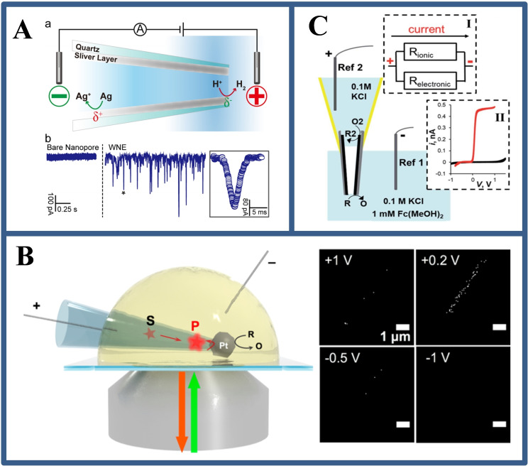
Single molecules analysis is an effective means to accurately explore information such as individual molecular behavior, electron transport processes, and dynamic structure‐activity relationships. The traditional detection techniques are very difficult or even unobtainable. Recently, the solid‐state nanopore‐based techniques have emerged as a promising technique for single molecules detection. However, it is difficult to accurately obtain the transient electrical signal of single molecule because of the extremely fast speed of the single molecule passing through the nanopore. In order to improve the analytical sensitivity of nanoporous single‐molecule technology, the researchers [50] used the electrochemical confined nanopores constructed by Aerolysin to achieve ultrasensitive recognition of single‐base differences of DNA molecules. In addition, the real‐time observation of the “step‐by‐step” degradation of single stranded DNA by exonucases was completed at the single molecular level, providing a highly sensitive analysis system for exploring the structure‐activity relationship of individual enzymes. At the same time, based on the understanding of nanopore channels for many years, researchers constructed a new mechanism for “confined” electrochemical analysis of nanopore, providing a new idea for the study of dynamic redox process of single molecules. [51] However, it is difficult to precisely and controllably fabricate solid‐state nanopores with a diameter less than 2 nm. Hence, it is a big challenge of solid‐state nanopores for direct small molecules assay. As shown in Figure 9A, Gao et al. [52] developed a WNE with an inner wall modified by Ag layer, which achieves the supersensitive assay for single self‐generated H2 molecules and single Ag ions by monitoring the enhanced ionic signatures. The unique WNE design provides a simple, label‐free and ultrasensitive detection idea for various small molecules or ions, especially for redox‐reactive species. For example, Fan et al. [53] reported electrochemical nanocell with a Pt‐based WNE to monitor single redox molecules. First, Pt particle were deposited on the orifice of the nanocapillary tip to form a closed Pt‐based nanocell. Then, the resorufin molecules with high fluorescence intensity are generated on the inner Pt‐based WNE surface due to unique properties of the nanocell. The fluorescent molecules were optically detected and counted by spot intensity (Figure 9B). In this strategy, the confined space of the nanocell limits the movement of redox species, increasing the probability of instantaneous adsorption of molecules on the inner wall of the capillary. Coupled with the longer diffusion distance, the probability of fluorescence detection is further increased. This research reveals the unique appeal of fluorescence‐based electrochemical detection in studying redox events.
Figure 9.
(A) Illustration of H2 and Ag+ BPE sensing by a WNE at the single molecules level and the raw current traces of the bare nanopore and the WNE. Reproduced with permission from Ref. [52]. Copyright 2017, American Chemical Society; (B) Schematic illustration of the Pt‐based nanocell used to image single resorufin molecules and the imaging for single fluorescent molecule locations at different potentials. Reproduced with permission from Ref. [53]. Copyright 2018, American Chemical Society; (C) Schematic representation, equivalent scheme and cyclic voltammograms of the carbon layer based bipolar nanoelectrode. Reproduced with permission from Ref. [54]. Copyright 2014, American Chemical Society.
Moreover, The conductive layer inside the nanocapillary replaced by carbon layer can also as a wireless bipolar nanoelectrode for the study of two opposite electrochemical reactions. [54] As shown in Figure 9C, the carbon‐based WNE could be used as multifunctional electrochemical probes to record the ion current through the nanocapillary and the current generated by redox of molecules on the nanoring at the tip of carbon‐based nanocapillary.
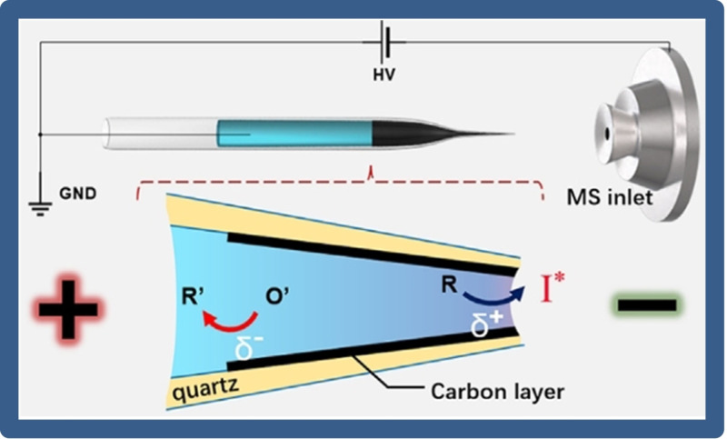
Understanding the mechanism of an electrochemical reaction is highly dependent on the accurate and sensitive assay of electrically generated short‐lived intermediates. Recently, Taking advantage of the asymmetric reactivity of the WNE surface, Xu′s group [55] developed a novel mass spectrometry method for the precise detection of reaction intermediates (Figure 10). It allows exploring the fast kinetics of redox reactions within the electrode‐electrolyte interfaces using mass spectrometry. By preparing carbon‐based WNEs, the effective combination of BPE and nano‐electrospray ionization mass spectrometry was successfully realized for the identification of short‐lived electrogenerated intermediates. The ingenious design lays a foundation for exploring ultrafast initial steps of microsecond‐scale redox reactions.
Figure 10.
Illustration of BPE coupled with nanoelectrospray ionization mass spectrometry to detect electrogenerated intermediates. Reproduced with permission from Ref. [55]. Copyright 2020, Wiley.
6. Conclusions and Outlook
BPE at micro/nanoscale has been significantly developed in the past two decades, benefiting from the growth of nanotechnology. In the mini review, we winnowed the recent advances of BPE in analytical chemistry. BPE has some inherent properties that make it have advantages that traditional electrochemistry cannot achieve: (i) it enables electrochemical reactions on objects to proceed without direct physical contact with a power supply. This wireless nature allows miniaturization and parallel processing for tens of thousands of objects with only one pair of feeder electrodes; (ii) the gradient potential distribution in BPE systems are available for the controllable preparation of Janus‐like objects and other micro/nanoscale materials; (iii) the asymmetrical reactions of BPE and the remarkable confinement effects at micro/nanoscale surfaces significantly improve the ability for tracing the dynamic redox process of individual analytes in a tiny space; (iv) exploit the properties of micro/nano‐confined BPE to regulate the transport of ions and characterize heterogeneous populations of single entities.
Except for these evolving advancements and emerging opportunities, there are some important challenges that limit the development of BPE. For example, in resource‐limited environments and in situ characterization of electrochemical reactions, the practical application of BPE is hindered by the liquid‐phase reporting bulk and will extend towards solid‐state reporting electrolytes such as hydrogels. In microchannels or nanocapillary, the high power supply and the electrophoretic phenomena induced by BPE are not conducive to in situ electrochemical analysis of various regions in living cells. Moreover, the detailed induction mechanism for BPE in a confined space at micro/nanoscale level and the related data analysis are still in their infancy and look forward to the continuous discovery. Finally, complementary spectroscopic and spectroscopic measurement methods are needed to establish structure‐function relationships when driving from ensemble to single entities measurement. In conclusion, BPE is an ever‐changing research field that presents crucial scientific challenges and provides innovative solutions to some analytical problems. By assessing the progress of the past decade, we can clearly see that the field has not yet reached its peak and is booming.
Conflict of interest
The authors declare no conflict of interest.
7.
Biographical Information
Yu‐Ling Wang obtained her Ph.D. degree from Nanjing University. She is currently a research scientist working in Prof. Yan‐Ming Liu's and Jun‐Tao Cao's group in the Department of Chemistry and Chemical Engineering at Xinyang Normal University. Her research focuses on electrochemiluminescence biochemical analysis; single cell electrochemical detection. She has authored and co‐authored 20 papers.

Biographical Information
Jun‐Tao Cao obtained his Ph.D. degree from Nanjing University. Currently, he works at the Xinyang Normal University as a full professor and his research interests include electrochemiluminescent/photoelectrochemical biosensing. In recent years, his work mainly focused on the study of the interface behaviour of biomolecules and photoelectric nanosensing in micro/nano system. He has authored and co‐authored more than 90 papers, and most of them are related to protein assay.

Biographical Information
Yan‐Ming Liu obtained his Ph.D. degree from Wuhan University. Since 2002, he has been a full professor of chemistry at the Xinyang Normal University. His research interests focus on the bioanalysis based on the combination technique of chemiluminescence/electrochemiluminescence, and fabrication of photoelectrochemical and electrochemiluminescent biosensors. He has authored and co‐authored over 180 papers.

Acknowledgements
This work was supported by the National Natural Science Foundation of China (Grant 21874115 and 21675136), Zhongyuan Thousand Talents Program of Henan Province (ZYQR201912127 and ZYQR201912177), Key Scientific Research Project of Higher Education Institutions in Henan Province (22 A150022), and Nanhu Young Scholar Supporting Program of XYNU.
Y.-L. Wang, J.-T. Cao, Y.-M. Liu, ChemistryOpen 2022, 11, e202200163.
Data Availability Statement
The data that support the findings of this study are openly available in American Chemical Society; Elsevier; Royal Society of Chemistry; Springer Nature; Wiley; Springer.
References
- 1.
- 1a. Anand R. K., Sheridan E., Hlushkou D., Tallarek U., Crooks R. M., Lab Chip 2011, 11, 518–527; [DOI] [PubMed] [Google Scholar]
- 1b. Fosdick S. E., Knust K. N., Scida K., Crooks R. M., Angew. Chem. Int. Ed. 2013, 52, 2–21. [DOI] [PubMed] [Google Scholar]
- 2.M. Atobe, Wiley: Hoboken, NJ, 2014; Chapter 1.
- 3. Crooks R. M., ChemElectroChem 2016, 3, 357–359. [Google Scholar]
- 4.
- 4a. Backhurst J. R., Coulson J. M., Goodridge F., Plimley R. E., Fleischmann M., J. Electrochem. Soc. 1969, 116, 1600–1607; [Google Scholar]
- 4b. Fleischmann M., Oldfield J. W., J. Electroanal. Chem. Interfacial Electrochem. 1971, 29, 211–230; [Google Scholar]
- 4c. Goodridge F., King C. J. H., Wright A. R., Electrochim. Acta 1977, 22, 347–352. [Google Scholar]
- 5.
- 5a. Rahn K. L. and Anand R. K., Anal. Chem. 2021, 93, 103–123; [DOI] [PubMed] [Google Scholar]
- 5b. Bouffier L., Zigah D., Sojic N., Kuhn A., Annu. Rev. Anal. Chem. 2021, 14, 65–86; [DOI] [PubMed] [Google Scholar]
- 5c. Shida N., Zhou Y., Inagi S., Acc. Chem. Res. 2019, 52, 2598–2608; [DOI] [PubMed] [Google Scholar]
- 5d. Koefoed L., Pedersen S. U., Daasbjerg K., Curr. Opin. Electrochem. 2017, 2, 13–17. [Google Scholar]
- 6. Bazant M. Z., Chu K. T., Bayly B. J., SIAM J. Appl. Math. 2005, 65, 1463–1484. [Google Scholar]
- 7. Whitesides G. M., Stroock A. D., Phys. Today 2001, 54, 42–48. [Google Scholar]
- 8.
- 8a. Fosdick S. E., Knust K. N., Scida K., Crooks R. M., Angew. Chem. Int. Ed. 2013, 52, 10438–10456; [DOI] [PubMed] [Google Scholar]; Angew. Chem. 2013, 125, 10632–10651; [Google Scholar]
- 8b. Loget G., Zigah D., Bouffier L., Sojic N., Kuhn A., Acc. Chem. Res. 2013, 46, 2513–2523. [DOI] [PubMed] [Google Scholar]
- 9.
- 9a. Loget G., Roche J., Kuhn A., Adv. Mater. 2012, 24, 5111–5116; [DOI] [PubMed] [Google Scholar]
- 9b. Warakulwit C., Nguyen T., Majimel J., Delville M.-H., Lapeyre V., Garrigue P., Ravaine V., Limtrakul J., Kuhn A., Nano Lett. 2008, 8, 500–504. [DOI] [PubMed] [Google Scholar]
- 10.
- 10a. Ying Y.-L., Hu Y−X., Gao R., Yu R., Gu Z., Lee L. P., Long Y−T., J. Am. Chem. Soc. 2018, 140, 5385–5392; [DOI] [PubMed] [Google Scholar]
- 10b. Ismail A., Voci S., Pham P., Leroy L., Maziz A., Descamps L., Kuhn A., Mailley P., Livache T., Buhot A., Leichlé T., Bouchet-Spinelli A., Sojic N., Anal. Chem. 2019, 91, 8900–8907; [DOI] [PubMed] [Google Scholar]
- 10c. Eden A., Scida K., Arroyo-Curras N., Eijkel J. C. T., Meinhart C. D., Pennathur S., Electrochim. Acta 2020, 330, 135275; [Google Scholar]
- 10d. Hao R., Fan Y., Zhang B., J. Am. Chem. Soc. 2017, 139, 12274–12282. [DOI] [PubMed] [Google Scholar]
- 11. Karimian N., Hashemi P., Afkhami A., Bagheri H., Curr. Opin. Electrochem. 2019, 17, 30–37. [Google Scholar]
- 12.
- 12a. Duval J., Kleijn J. M., van Leeuwen H. P., J. Electroanal. Chem. 2001, 505, 1–11; [Google Scholar]
- 12b. Duval J., Minor M., Cecilia J., Van Leeuwen H. P., J. Phys. Chem. B 2003, 107, 4143–4155; [Google Scholar]
- 12c. Duval J. F., Buffle J., van Leeuwen H. P., J. Phys. Chem. B 2006, 110, 6081–6094. [DOI] [PubMed] [Google Scholar]
- 13. Cattarin S., Musiani M. M., J. Electrochem. Soc. 1995, 142, 3786–3792. [Google Scholar]
- 14. Guerrette J. P., Oja S. M., Zhang B., Anal. Chem. 2012, 84, 1609–1616. [DOI] [PubMed] [Google Scholar]
- 15.
- 15a. Oja S. M., Zhang B., ChemElectroChem 2016, 3, 457–464; [DOI] [PMC free article] [PubMed] [Google Scholar]
- 15b. Zheng X.-W., Chin. J. Anal. Chem. 2014, 42, 1220–1223; [Google Scholar]
- 15c. Wu S., Zhou Z., Xu L., Su B., Fang Q., Biosens. Bioelectron. 2014, 53, 148–153. [DOI] [PubMed] [Google Scholar]
- 16. Chow K. F., Chang B. Y., Zaccheo B. A., Mavré F., Crooks R. M., J. Am. Chem. Soc. 2010, 132, 9228–9229. [DOI] [PubMed] [Google Scholar]
- 17. Fosdick S. E., Crooks R. M., J. Am. Chem. Soc. 2012, 134, 863–866. [DOI] [PubMed] [Google Scholar]
- 18. Fosdick S. E., Berglund S. P., Mullins C. B., Crooks R. M., ACS Catal. 2014, 4, 1332–1339. [Google Scholar]
- 19. Ramakrishnan R., Shannon C., Langmuir 2010, 26, 4602–4606. [DOI] [PubMed] [Google Scholar]
- 20.
- 20a. Loget G., Larcade G., Lapeyre V., Garrigue P., Warakulwit C., Limtrakul J., Delville M. H., Ravaine V., Kuhn A., Electrochim. Acta 2010, 55, 8116–8120; [Google Scholar]
- 20b. Loget G., Lapeyre V., Garrigue P., Warakulwit C., Limtrakul J., Delville M. H., Kuhn A., Chem. Mater. 2011, 23, 2595–2599. [Google Scholar]
- 21. Koizumi Y., Nishiyama H., Tomitaa I., Inagi S., Chem. Commun. 2018, 54, 10475–10478. [DOI] [PubMed] [Google Scholar]
- 22. Loget G., Kuhn A., J. Am. Chem. Soc. 2010, 132, 15918–15919. [DOI] [PubMed] [Google Scholar]
- 23. Bradley J. C., Babu S., Carroll B., Mittal A., J. Electroanal. Chem. 2002, 522, 75–85. [Google Scholar]
- 24. Baek S., Kwon S. R., Yeon S. Y., Yoon S.-H., Kang C. M., Han S. H., Lee D., Chung T. D., Anal. Chem. 2018, 90, 4749–4755. [DOI] [PubMed] [Google Scholar]
- 25.
- 25a. Zhang X., Zhang L., Zhai Q., Gu W., Li J., Wang E., Anal. Chem. 2016, 88, 2543–2547; [DOI] [PubMed] [Google Scholar]
- 25b. Jaworska E., Michalska A., Maksymiuk K., Electrochim. Acta 2018, 284, 321–327; [Google Scholar]
- 25c. Dumitrescu I., Anand R. K., Fosdick S. E., Crooks R. M., J. Am. Chem. Soc. 2011, 133, 4687–4689. [DOI] [PubMed] [Google Scholar]
- 26.
- 26a. Jaworska E., Michalska A., Maksymiuk K., Electroanalysis 2020, 32, 812–819; [Google Scholar]
- 26b. Jaworska E., Michalska A., Maksymiuk K., Anal. Chem. 2019, 91, 15525–15531. [DOI] [PubMed] [Google Scholar]
- 27. Ma X., Qi L., Gao W., Yuan F., Xia Y., Lou B., Xu G., Electrochim. Acta 2019, 308, 20–24. [Google Scholar]
- 28.
- 28a. Shi X., Gao R., Ying Y.-L., Si W., Chen Y.-F., Long Y.-T., ACS Sens. 2016, 1, 1086–1090; [Google Scholar]
- 28b. Ying Y.-L., Hu Y.-X., Gao R., Yu R.-J., Gu Z., Lee L. P., Long Y.-T., J. Am. Chem. Soc. 2018, 140, 5385–5392; [DOI] [PubMed] [Google Scholar]
- 28c. Notingher I., Elfick A., J. Phys. Chem. B 2005, 109, 15699–15706; [DOI] [PubMed] [Google Scholar]
- 28d. Li H., Zhang T., Zhou H., Zhang Z., Liu M., Wang C., ChemElectroChem 2021, 8, 1473–1477. [Google Scholar]
- 29.
- 29a. Ye C., Jiao Y., Chao D., Ling T., Shan J., Zhang B., Gu Q., Davey K., Wang H., Qiao S.-Z., Adv. Mater. 2020, 32, 1907557; [DOI] [PubMed] [Google Scholar]
- 29b. Xu S., Zhang W., Liu X., Han X., Bao X., J. Am. Chem. Soc. 2009, 131, 13722–13727. [DOI] [PubMed] [Google Scholar]
- 30.
- 30a. Bazant M. Z., Chu K. T., Bayly B. J., SIAM J. Appl. Math. 2005, 65, 1463–1484; [Google Scholar]
- 30b. Vetter K. J., E Academic Press, Inc.: New York 1967; [Google Scholar]
- 30c. Newman J. S., Prentice-Hall, Inc.: New Jersey 1973. [Google Scholar]
- 31. Eden A., Scida K., Arroyo-Currás N., Eijkel J. C. T., Meinhart C. D., Pennathur S., J. Phys. Chem. C 2019, 123, 5353–5364. [Google Scholar]
- 32. Gao R., Cui L. F., Ruan L. Q., Ying Y. L., Long Y. T., JoVE 2019, 145, e59003. [DOI] [PubMed] [Google Scholar]
- 33. Gao R., Lin Y., Ying Y.-L., Hu Y.-X., Xu S.-W., Ruan L.-Q., Yu R.-J., Li Y.-J., Li H.-W., Cui L.-F., Long Y.-T., Nat. Protoc. 2019, 14, 2015–2035. [DOI] [PubMed] [Google Scholar]
- 34.
- 34a. Richter M. M., Chem. Rev. 2004, 104, 3003–3036; [DOI] [PubMed] [Google Scholar]
- 34b. Miao W., Chem. Rev. 2008, 108, 2506–2553. [DOI] [PubMed] [Google Scholar]
- 35. Arora A., Eijkel J. C., Morf W. E., Manz A., Anal. Chem. 2001, 73, 3282–3288. [DOI] [PubMed] [Google Scholar]
- 36. Wu M.-S., Yuan D.-J., Xu J.-J., Chen H.-Y., Anal. Chem. 2013, 85, 11960–11965. [DOI] [PubMed] [Google Scholar]
- 37. Wu M.-S., Xu B.-Y., Shi H.-W., Xu J.-J., Chen H.-Y., Lab Chip 2011, 11, 2720–2724. [DOI] [PubMed] [Google Scholar]
- 38. Wu M.-S., Liu Z., Xu J.-J., Chen H.-Y., ChemElectroChem 2016, 3, 429–435. [Google Scholar]
- 39. Ge S. G., Zhao J. G., Wang S. P., Lan F. F., Yan M., Yu J. H., Biosens. Bioelectron. 2018, 102, 411–417. [DOI] [PubMed] [Google Scholar]
- 40. Shi H.-W., Zhao W., Liu Z., Liu X.-C., Xu J.-J., Chen H.-Y., Anal. Chem. 2016, 88, 8795–8801. [DOI] [PubMed] [Google Scholar]
- 41. Cao J. T., Wang Y. L., Zhang J. J., Dong Y. X., Liu F. R., Ren S. W., Liu Y. M., Anal. Chem. 2018, 90, 10334–10339. [DOI] [PubMed] [Google Scholar]
- 42. Wang Y., Jin R., Sojic N., Jiang D., Chen H.-Y., Angew. Chem. Int. Ed. 2020, 59, 10416–10420; [DOI] [PubMed] [Google Scholar]; Angew. Chem. 2020, 132, 10502–10506. [Google Scholar]
- 43. Wang Y., Jiang D., Chen H.-Y., CCS Chem. 2021, 3, 2268–2274. [Google Scholar]
- 44. Gao R., Ying Y.-L., Li Y.-J., Hu Y.-X., Yu R.-J., Lin Y., Long Y.-T., Angew. Chem. Int. Ed. 2018, 57, 1011–1015; [DOI] [PubMed] [Google Scholar]; Angew. Chem. 2018, 130, 1023–1027. [Google Scholar]
- 45. Han C., Hao R., Fan Y., Edwards M. A., Gao H., Zhang B., Langmuir 2019, 35, 7180–7190. [DOI] [PubMed] [Google Scholar]
- 46. Lu S.-M., Li Y.-J., Zhang J.-F., Wang Y., Ying Y.-L., Long Y.-T., Anal. Chem. 2019, 91, 10361–10365. [DOI] [PubMed] [Google Scholar]
- 47. Deng Z., Renault C., Chem. Sci. 2021, 12, 12494–12500. [DOI] [PMC free article] [PubMed] [Google Scholar]
- 48. Zhou J., Lin J., Huang X., Zhou Y., Chen Y., Xia J., Wang H., Xie Y., Yu H., Lei J., Nature 2018, 556, 355–359. [DOI] [PubMed] [Google Scholar]
- 49. Naguib M., Mochalin V. N., Barsoum M. W., Gogotsi Y., Adv. Mater. 2014, 26, 992–1005. [DOI] [PubMed] [Google Scholar]
- 50. Wang Y.-Q., Li M.-Y., Qiu H., Cao C., Wang M.-B., Wu X.-Y., Huang J., Ying Y.-L., Long Y.-T., Anal. Chem. 2018, 90, 7790–7794. [DOI] [PubMed] [Google Scholar]
- 51. Shi X., Gao R., Ying Y.-L., Si W., Chen Y.-F., Long Y.-T., ACS Sens. 2016, 1, 1086–1090. [Google Scholar]
- 52. Gao R., Ying Y.-L., Hu Y.-X., Li Y.-J., Long Y.-T., Anal. Chem. 2017, 89, 7382–7387. [DOI] [PubMed] [Google Scholar]
- 53. Fan Y., Hao R., Han C., Zhang B., Anal. Chem. 2018, 90, 13837–13841. [DOI] [PubMed] [Google Scholar]
- 54. Hu K., Wang Y., Cai H., Mirkin M. V., Gao Y., Friedman G., Gogotsi Y., Anal. Chem. 2014, 86, 8897–8901. [DOI] [PubMed] [Google Scholar]
- 55. Hu J., Zhang N., Zhang P.-K., Chen Y., Xia X.-H., Chen H.-Y., Xu J.-J., Angew. Chem. Int. Ed. 2020, 59, 18244–1824; [DOI] [PubMed] [Google Scholar]; Angew. Chem. 2020, 132, 18401–18405. [Google Scholar]
Associated Data
This section collects any data citations, data availability statements, or supplementary materials included in this article.
Data Availability Statement
The data that support the findings of this study are openly available in American Chemical Society; Elsevier; Royal Society of Chemistry; Springer Nature; Wiley; Springer.


