Abstract
With the advent of augmented reality (AR), the use of AR‐guided systems in the field of medicine has gained traction. However, the wide‐scale adaptation of these systems requires highly accurate and reliable tracking. In this work, the tracking accuracy of two technology platforms, LiDAR and Vuforia, are developed and rigorously tested for a catheter placement neurological procedure. Several experiments (900) are performed for each technology across various combinations of catheter lengths and insertion trajectories. This analysis shows that the LiDAR platform outperformed Vuforia; which is the state‐of‐the‐art in monocular RGB tracking solutions. LiDAR had 75% less radial distance error and 26% less angle deviation error. Results provide key insights into the value and utility of LiDAR‐based tracking in AR guidance systems.
1. INTRODUCTION
Use of intraoperative image guidance technologies has become routine in many neurosurgery practices. Both spine and cranial surgical procedures currently leverage guidance technologies to improve surgeon performance and achieve better patient outcomes. In spinal procedures, CT‐guided pedicle screw placement has gained popularity, which has resulted in greater screw placement accuracy and lower complication rates compared to freehand or fluoroscopic techniques [1, 2, 3, 4, 5, 6]. In cranial procedures, image guidance has been frequently employed for tumour surgery, but the link to gross total resection rates and subsequently progression‐free survival and overall survival is still debated [7, 8, 9, 10].
Augmented reality (AR) is the overlay of 3D computer‐generated interactive objects on the surrounding environment. AR is presented in several formats in neurosurgery: (1) Headset mounted displays, for example, XVision1, HoloLens 22, and Magic Leap One3, which display planar or 3D objects through the headset display, (2) AR overlays displayed on a smartphone, tablet, or monitor [11, 12, 13, 14] and (3) AR overlays injected into oculars of the microscope, for example, Microscopic Navigation4. The latter is a form of pseudo‐AR in which the generated image is static and mostly lacks a user‐AR interactive component, it also sometimes does not rely on the spatial anchoring and spatial understanding that define modern headset‐based AR.
As AR technologies have matured over the last decade, applications in neurosurgery have grown. Foremost among these applications are the demonstrated successes in spine surgery, specifically technologies that enable the surgeon to place pedicle screws more accurately and efficiently [15, 16, 17, 18, 19].
Cranial applications of headset‐based AR, the focus of this work, have mostly concentrated on preoperative planning because existing AR technologies are not yet sophisticated enough to support intraoperative microscopic navigation. However, contemporary technologies have enabled nascent success in microscope navigation; ranging across skull base, vascular, and oncologic operative procedures [20, 21, 22, 23, 24, 25, 26, 27, 28, 29, 30]. Recently, the effectiveness of AR has been tested for ventriculostomy since freehand procedures often lead to low success rates [31]. [32, 33, 34] have proposed and tested navigation systems that help guide surgeons place catheters with high accuracy. However, these systems have not yet been tested in clinical settings. Widescale adoption of a headset‐based AR cannot occur without first demonstrating acceptable accuracy. Although there is no predefined criterion for greatest allowable radial error and angular error, these values must be at or below current FDA‐approved neuronavigation systems, that is, 2 mm and 2° respectively [35, 36].
Many techniques have been proposed to register and track patient anatomy and surgical tools in AR‐assisted neurosurgery. The most predominant approaches leverage 2D cameras to detect and track planar fiducial markers [32, 34, 37–40]. These approaches rely on the geometric characteristics and dimensions of the fiducials to be known. This allows a system to calculate the angle and distance from the camera's view, and through further transformations, the global coordinates of the object. A particularly effective, commercial implementation of this technical approach exists inside the Vuforia AR‐toolkit5.
Here, we build on a more nascent approach to register and track anatomy and tools; one that leverages light detection and ranging (LiDAR) technology, a tracking technique that uses principles of radar, but with laser light instead of electromagnetic radiation. Existing literature has only studied the use of LiDAR in registration [41], not tracking of anatomy and tools. Further, no systematic comparison between visual and LiDAR‐based tracking accuracy has been performed. Here, we present such a systematic evaluation. Through a series of controlled experiments, this work compares the radial and angular tracking error for a specific neurosurgical procedure, placement of an external ventricular drain. Results indicate that LiDAR provides a significant improvement in radial error and a modest reduction in angle deviation compared to the 2D tracking approach. This work contributes new knowledge to the clinical and scientific development of AR‐assisted neurosurgical applications and technologies.
2. METHODS
2.1. 3D models
We used two custom 3D printed skull models that were obtained from CGTrader6. We had these models evaluated by two neurosurgeons for anatomical accuracy, in particular, we asked them to confirm: (1) if the skull was representative in size, scale, proportion and structural features and (2) if the target location was representative of a target in an actual clinical setting. Both neurosurgeons concluded that the models were adequate for the evaluation of neuronavigation technologies. The procedure for developing the phantom was inspired by prior work. We strived to be consistent in our approach to the anatomical representation used in prior work [42]. We printed these models using an Ultimaker S5. We added four platforms (highlighted in orange in Figure 1) to support the placement of fiducial markers (ArUco markers and QR codes). Although the setup could in theory work with just one platform, we used four to allow for best‐case tracking, as the focus of this work was to obtain a comparison of the technologies with optimal operating and tracking assumptions. These platforms were 60 mm‐by‐60 mm in length and width. The thickness was 10 mm, although this measure was trivial since it only acted as a support to hold the fiducial markers in place. Finally, we added a base (highlighted in green in Figure 1) and target (highlighted in red in Figure 1) point to the model.
FIGURE 1.
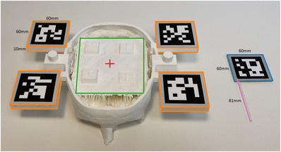
Custom 3D‐printed skull model & laser cut catheter. Top of the skull is removed to provide access for the experimental configuration
Instead of affixing a fiducial marker to a real ventricular catheter, we replaced the catheter with a laser‐cut localizer tool as shown in Figure 1. This allowed a fiducial marker to be affixed to a ridged, immobile proxy. This approach is similar to prior work that performs tool tracking [43]. This was also done to further control variability that could be introduced by the catheter bend. For the remainder of the paper, we refer to this proxy tool as a catheter.
We used catheters of varying lengths (67 mm, 74 mm, 81 mm, 88 mm, 95 mm) for both experimental setups. Figure 1 shows a catheter of length 81 mm (highlighted in pink). These lengths were selected as they are near or beyond the maximum distance from the entry point to target for a deep brain biopsy, thus accuracy of a system at these depths is the most rigorous evaluation of its usability in neurosurgical procedures. We added a 60 mm‐by‐60 mm platform at the top end of the catheters (highlighted in orange in Figure 1) for marker placement. The thickness of this platform was 2 mm. Skull models and catheters for both our setups had the exact same design.
2.2. LiDAR technology platform
2.2.1. Camera
We used an Intel RealSense L515 LiDAR camera to obtain red, green, blue ‐ depth (RGB‐D) images of the environment. We used the highest settings available on the LiDAR for our experiments, that is, 1024 × 768 @ 30fps for the depth camera and 1920 × 1080 @ 30fps for the red, green, blue (RGB) camera. Fiducial Markers: We used ArUco markers [44] for this setup as the LiDAR has a low‐resolution RGB camera and was not able to properly detect the QR codes at a distance (roughly 30 cm) using the OpenCV [45] library. Instead, we used ArUco markers that offered more robust detection. At first, we experimented with 60 mm‐by‐ 60 mm ArUco markers but they were highly susceptible to yielding wrong depths as a marker corner was often detected a few pixels outside of the platform. Thus, we used 50 mm‐by‐50 mm markers but kept the platform the same size, this eliminated our depth estimate error along the edge of the marker. Catheter markers were also adjusted accordingly.
2.2.2. Application and target estimation
As a pre‐step we extracted the 3D coordinates of all the ArUco marker corners , as well as the target point , and the incision point in the model coordinate system. Although the experiment used a single target, we used various incision points to simulate trajectories incident at different angles to the target. Next, we used the LiDAR to get the 3D coordinates of the ArUco marker corners in the LiDAR coordinate system . These ArUco markers were detected using OpenCV. In order to account for noise in the depth data, temporal smoothing was applied with a window size of 20 frames, for example, a final depth frame was estimated by averaging 20 frames.
| (1) |
We implemented a random sample consensus (RANSAC) [46] version of a rigid transform estimator in Python. We chose RANSAC to allow for robust transform estimates even in cases where the LiDAR returned noisy depth estimates of the points of interest. Our algorithm uses point correspondences (among and ) and returns a transformation matrix that describes a relationship between points in the model coordinate system and the LiDAR coordinate system (Figure 2). This can be expressed as a matrix multiplication, shown in Equation (1), where . Our algorithm requires three non‐collinear points to yield correct estimates of . The was then used in Equation (1) to get the coordinates for and . Note that in an actual operating environment lies inside the human skull and is not visible to the eye. We used OpenCV to detect two points on the catheter ‐ the bottom left and the top left corners of the ArUco marker. By design, both of these points were kept in line with the tip of the catheter to create a single vector representing the catheter direction in space.
FIGURE 2.
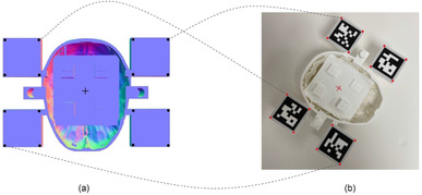
TM estimation using point correspondences. (a) Black points represent Cmodel and the centre of plus sign represents Tmodel. (b) Red points represent and the centre of plus sign represents. The dotted lines show a subset of point correspondences. The incision point is not shown since it lies above the surface. The red and black points are related to each other by
2.3. Vuforia technology platform
2.3.1. Camera
We used a Logitech C615 camera for this experimental setup. We used the highest settings available on the device; 1920 × 1080 @30fps. Fiducial Markers: Since Vuforia's algorithm relies on feature detection and matching to perform tracking and registration, we used QR codes due to their texture richness. Unlike the LiDAR, Vuforia does not estimate the depth of the scene using time‐of‐flight, but instead uses both data provided by the user such as dimensions of the QR codes and feature points to get depth estimates using solely an RGB camera. Although the Vuforia algorithm is proprietary, we were able to confirm this depth estimation approach, as the system was able to produce depth estimates using only an RGB camera. This was verified on a computer using a simple RGB camera and on the HoloLens 2 by intentionally occluding the time‐of‐flight (ToF) camera on the device; in both cases Vuforia was able to track and register the fiducial markers, yielding depth estimates of the scene.
2.3.2. Application and target estimation
We used Unity (version 2020.3.12f1) and Vuforia SDK (version 10.0.12) to develop the technology platform for this experimental setup. We imported the skull and the catheter models into Unity and then added image targets (QR codes) and positioned them onto their respective platforms. We used a total of nine image targets (4 for the skull and 5 for the catheters), however, for the experiment, catheters were tested one at a time. We manually added a target and an incision point in the Unity scene as game objects. We averaged positional and rotational values over a window of 20 frames to achieve temporal smoothing. In case more than one QR code was being tracked, we arbitrarily selected one. While we experimented with tracking using the averages of multiple QR codes, it produced wide swings in the estimated target location because Vuforia was inconsistent in the number of fiducials it tracked in each frame. We observed that limiting the number of tracked QR codes to one at a time led to more consistent target location estimates. To track the catheter, we manually added two points in the Unity scene. These points were placed to be in line with the catheter tip. Once the Vuforia technology platform was started, the software was able to identify the coordinates for all points in the scene.
2.4. Experimental design
Applications developed using Vuforia can be deployed and run on the HoloLens, but they only utilize the RGB camera. There is no SDK available that allows the development of a HoloLens application that uses the LiDAR time‐of‐flight (ToF) sensor on the HoloLens. Further, while there are research‐level APIs to the ToF sensor on the HoloLens, consultations with the manufacturer (Microsoft) indicated the sensor is primarily tasked with hand and gesture recognition. Utilizing it for other purposes interferes with, and significantly degrades the quality of hand tracking and gesture functionality. Thus, we chose to stay platform agnostic and did not evaluate our technologies on the HoloLens. This ensured ecological validity and a fair and equal comparison of the two technology platforms.
All experiments for both technology platforms were conducted in similar lighting conditions in a windowless research lab. The LiDAR and camera were placed in similar positions, roughly 30 cm from the target, for both setups to ensure consistency between and within experiments. We used a Dell Precision 5820 Desktop equipped with an Intel Xeon W‐2223 3.60 Ghz CPU, NVIDIA Quadro RTX 6000 GPU, and 72 GB of RAM for all experiments. Each of the 5 different catheter lengths were tested for 9 insertion trajectories and 20 measures were recorded for each catheter length/insertion trajectory pair. We define an experiment as a tuple (catheter length, insertion trajectory). Thus, we conducted 45 (5 * 9) experiments per technology platform (LiDAR/Vuforia) and recorded 20 values per each experiment. This yielded a total of 900 (5 * 9 * 20) recordings/trials for each technology platform.
Our evaluation methodology took an inverse approach compared to related literature (e.g. [42]). We measured the error of the system relative to an absolute ground truth by deliberately placing the catheter at the target at a specified trajectory. This methodology was deliberate, as we believe it further limits errors introduced by experimental methods (e.g. having to manually measure the distance between the catheter tip and the target for each experimental trial). We measured radial distance (Equation (2)) and angle deviation (Equation (3)) for each trial. The radial distance was calculated as the absolute difference between the real depth and the observed depth . The angle deviation was calculated as the angle between the real trajectory and the observed trajectory . Both and were set as inputs to the technology platform a priori.
| (2) |
| (3) |
To test various insertion trajectories, we laser cut two wedges (Figure 3a). For every experiment the catheter was attached to the wedges and was then held in place at the target by using a Helping Hand7. This ensured that the actual trajectory was being mimicked as accurately as possible to the ground truth in the experimental setup and remain consistent across trials. These angles were chosen based on the standard of care for catheter insertions; surgeons choose to enter the skull to minimize the distance the catheter needs to travel to reach at the target location. This process most commonly results in a right, or near right angle path of insertion. Hence, we only tested for small angle deviations −2° and 5° in both positive and negative x and y directions (Figure 3b). The actual experimental setup is shown in Figure 4.
FIGURE 3.
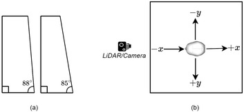
Experimental design configuration details. (a) Shows the wedges that were used to mimic various insertion trajectories. (b) Shows the directions of the trajectories from a top view (the nose of the skull is pointing towards the LiDAR or camera)
FIGURE 4.
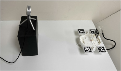
Experimental setup used for data collection. Note the fixed placement of the camera and skull. Also note the use of the laser cut wedged and magnetic arm that was used to hold setup still for data collection
To maintain the accuracy of our ground truth parameters, and , the catheters and wedges were first designed as models using Shapr3d. We were deliberate in this task as we wanted these models to align accurately with the virtual models. We used a Glowforge Pro laser cutter, that is accurate to 0.1 mm, to obtain physical models. We also verified the lengths of the catheters and the angles of the wedges using common measuring tools and found them to be accurate.
3. RESULTS
We present our results in an order of increasing comparison granularity. We start with a comparison between the technology platforms, LiDAR versus Vuforia, and then report differences observed across various conditions within each technology platform. Recall the two key measurements of the experiment: (1) Radial distance, , calculated as the absolute distance between the ground truth physical target and the system's estimation of the catheter tip; and (2) angle deviation, , the absolute difference between the ground truth measured angle and the system's estimation of the catheter angle, along a single axis of measurement. For all visualizations of the results, a blue line is used for LiDAR and an orange line for Vuforia results. A navy line is used for LiDAR results and a yellow line for Vuforia results.
3.1. Comparison of technology platforms
Measured mean radial distance () for the LiDAR technology platform was 0.99 mm ± 0.70 mm (mean ± standard deviation). Measured mean angle deviation () was 1.79° ± 0.72° (mean ± standard deviation). These measurements include the data collected from all 900 trials performed with the LiDAR technology platform. The measured mean radial distance for Vuforia was 4.02 mm (mean ± standard deviation). The measured mean angle deviation was 2.41° ± 1.02° (mean ± standard deviation). These measures include the data collected from all 900 trials performed with the Vuforia technology platform.
Figure 5a plots the distribution for both technologies. As shown, LiDAR yields a lower median and has a smaller range (2.99 mm) compared to Vuforia (7.08 mm). A Kruskal‐Wallis test was performed on and found a statistical significance between the two technology platforms (χ2 = 1057.51, p < 0.001, df = 1). Figure 5b shows the distribution for both technology platforms. LiDAR yields a lower median and has a slightly smaller range (3.79°) compared to Vuforia (5.27°). Note there are fewer outliers on the LiDAR data. A Kruskal–Wallis test was performed on and found a statistical significance between the two technology platforms (χ2 = 166.07, p < 0.001, df = 1).
FIGURE 5.
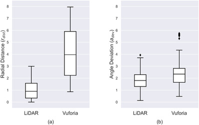
(a) dw and (b) distributions for both applications. All 900 recordings were used for these plots. The error bars represent the minimum and maximum. The diamonds correspond to outlier values
Figure 6 plots across different catheter lengths for both technology platforms. The x‐axis is the different catheter lengths tested; y‐axis is radial distance errors. A point on the plot corresponds to the average error for each catheter length tested with a specific technology platform. These measures collapse the data across the insertion trajectories. The Vuforia points in Figure 6 have been slightly shifted to avoid error bar overlap; it is not intended to represent different catheter lengths that were used between technology platforms. The analysis indicates LiDAR yields a lower across all catheter lengths and also has a lower variance when compared to Vuforia.
FIGURE 6.
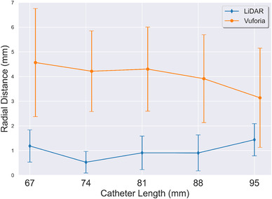
Effect of catheter length on radial distance (). Average across all insertion trajectories is reported. Error bars represent the standard deviation
Figure 7 plots across different insertion trajectories. The x‐axis is the different insertion trajectories tested; y‐axis is radial distance errors. A point on the plot corresponds to the average calculated radial distance measures for each insertion trajectory tested with a specific technology platform. Note two lines per technology platform are shown, a solid line for angle trajectories across x‐axis and a dashed line for angle trajectories across the y‐axis (refer to Figure 3b). These measures collapse the data across catheter lengths. The analysis showed LiDAR yields a consistently lower for all insertion trajectories. For both technologies, the is lower for the x insertion trajectories than the y insertion trajectories. Note, that the 0° insertion trajectory is the same for both x and y directions and was only calculated once, we have visualized it twice to preserve continuity in the plot.
FIGURE 7.
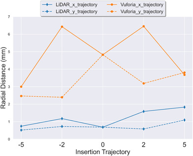
Effect of insertion trajectory on radial distance (). Average across all catheter lengths is reported. Error bars are not shown to preserve legibility of the figure. Standard deviations are reported in Figure 10
Figure 8 plots measurements across different catheter lengths for both technology platforms. The x‐axis is the different catheter lengths tested; y‐axis is the measured angle deviation. A point on the plot corresponds to the average calculated across all insertion trajectories with a specific technology platform. The Vuforia points in Figure 8 have been slightly shifted to the right to avoid error bar overlap; it is not intended to represent different insertion angles were used between technology platforms. The analysis indicates LiDAR yields a lower across all catheter lengths, except for the experimental data for catheter length 67 mm. The LiDAR had a lower variance when compared to Vuforia, except for the experimental data for catheter length 67 mm.
FIGURE 8.
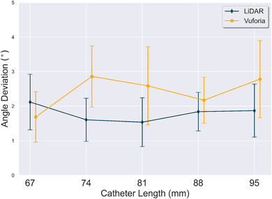
Effect of catheter length on angle deviation (). Average across all insertion trajectories is reported. Error bars represent the standard deviation
Figure 9 plots across different insertion trajectories. The x‐axis is the different insertion trajectories tested; y‐axis is measured angle deviation. A point on the plot corresponds to the average across all insertion trajectories with a specific technology platform. Two lines per technology platform are shown, a solid line for angle trajectories across x‐axis and a dashed line for angle trajectories across the y‐axis. These measures collapse the data across catheter lengths. The analysis indicates LiDAR performed best for the y‐axis insertion trajectory variations tested. In contrast, Vuforia performed better or near equal to LiDAR for the x‐axis insertion trajectory variations tested, except for the 5x insertion trajectory.
FIGURE 9.
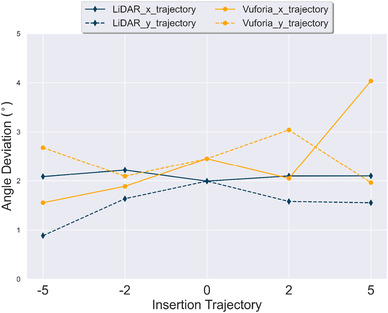
Effect of insertion trajectory on angle deviation (). Average across all catheter lengths is reported. Error bars are not shown to preserve legibility of the figure. Standard deviations are reported in Figure 11
For completeness we include Figure 10, which reports the mean and standard deviation of for all 45 experiments conducted for both the LiDAR and Vuforia technology platforms. Each measure was computed based on the 20 trials conducted per each experimental condition. Figure 12 provides an overall visual representation of radial distance error measurement means at the intersection of the insertion trajectory angles and catheter lengths tested. Two plots are used to reduce dimensionality across x and y insertion trajectories. A larger circle corresponds to a larger value.
FIGURE 10.

Radial distance results in mm for LiDAR and Vuforia for all 45 experiments. Entries in the table report mean and standard deviation respectively of the 20 trials per experiment
FIGURE 12.
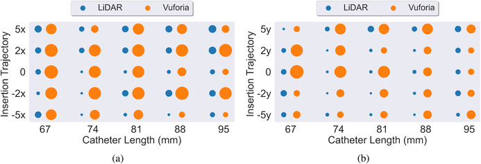
(a,b) Side by side comparison of LiDAR (blue) and Vuforia (orange) for radial distance () across x and y insertion trajectories respectively. Average of all 20 trials per experiment reported
Figure 11 reports the mean and standard deviation of for all 45 experiments conducted with the LiDAR and Vuforia technology platforms. Each measure was computed based on the 20 trials conducted per each experimental condition. Figure 13 provides an overall visual representation of angle deviation measurement means at the intersection of the insertion trajectory angles and catheter lengths tested. Again, two plots are used to reduce dimensionality across x and y insertion trajectories.
FIGURE 11.

Angle deviation results in degrees for LiDAR and Vuforia for all 45 experiments. Entries in the table report mean and standard deviation respectively of the 20 trials per experiment
FIGURE 13.
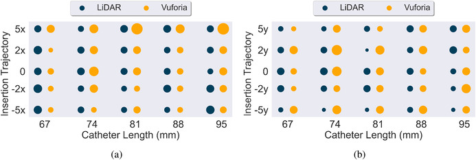
(a,b) Side by side comparison of LiDAR (navy) and Vuforia (yellow) for angle deviation () across x and y insertion trajectories respectively. Average of all 20 trials per experiment reported
4. DISCUSSION
4.1. Interpretation of results
The results indicate that trials conducted with the assistance of LiDAR technology are completed with a significantly smaller radial error () than trials conducted with the assistance of the Vuforia technology platform. We believe the additional error is a result of the difference in depth estimation techniques between the two platforms. As described above, the Vuforia platform estimates 3D position from a 2D camera view. This estimate is influenced by the quality and position of the 2D camera view and the resolution of the camera itself. In contrast, the LiDAR uses direct, time‐of‐flight measurements to measure the depth of surfaces within the sensor's field of view. While sensor view and resolution of the sensor influence error, there is no 2D to 3D conversion needed with this sensor. Thus, we argue the gain is due to the quality of the sensor to measure distance without interpolation.
Additional limitations of 2D camera‐based tracking should be noted. RGB camera vision techniques require an adequate number of keypoints (similar to scale‐invariant feature transform (SIFT) keypoints [47]) to be detected on the QR codes. The qualities of the QR code (e.g., number of edges) and the size of the QR code itself are known to impact tracking fidelity. The authors in [38] found an inverse relationship between the marker size and the error in the system using Vuforia and HoloLens 1. We observed an accurate performance in Vuforia's keypoint tracking even when small changes in camera position and illumination were adjusted. However, we did observe degradation in performance due to artifacts introduced by perspective transformation. For example, we observed decreased accuracy when QR codes were viewed at angles closer to the code's surface plane, for example, line of sight of the camera is almost parallel to the QR code surface plane.
The performance of LiDAR and Vuforia is similar for angle deviation (). This result is not particularly surprising as the technical approach to tracking orientation is similar for both platforms. Specifically, the error was calculated as a difference between two vectors— the intended trajectory and the tracked trajectory (the catheter). Errors in depth estimation shift the two trajectories equally while still preserving the angle between them. This was observed in our results, with both technology platforms yielding a low .
We noted in our results that the Vuforia technology platform performed differently across insertion angles for the radial distance error. Specifically, the deviations along the x insertion trajectories yielded more error compared to the y insertion trajectories. It is not clear from these results why these measurements were different. However, we conjecture this is due to perspective transformation artifacts, as explained above.
4.2. Comparison with prior work
This work is situated within a growing field of research related to surgical tool tracking and endoscopic navigation in neurosurgical settings. The baseline comparison measures of our study are consistent with measurements reported in prior work [32, 42, 48]. Furthermore, our work presents a detailed comparison of technology platform performance between 3D LiDAR tracking and the state‐of‐ the‐art monocular RGB camera‐based tracking solution, that is, Vuforia. We have situated the contribution within the current state‐of‐the‐art to help readers assess the insights of the work within a contemporaneous understanding of current technology capabilities and uses. Below we situate the current study within the most relevant literature to date.
The authors in [42] performed an evaluation of Vuforia with HoloLens 1 and found the point localization accuracy of the system to be < 2 mm 53% of the time, between 2 and 5 mm 40% of the time, and between 5 and 10 mm 7% of the time. These results also include a mean holographic drift of 1.41 mm due to the holographic overlay. Their experimental design used a single user to perform all the experiments. Their work differs from ours in the way error was calculated. In their experiment, the methodology of measurement consisted of deliberately marking a point on the surface of the object, and then measuring that difference manually. It is important to note that with this approach a target in reality might not lie on the marked surface (e.g. the target could be along a parallel plane). This approach may have underestimated the error performance of the technology platform for radial error. Further, this prior experiment only measured guidance performance and did not track the catheter (or any tool) as an experimental construct.
The authors in [32] performed ventriculostomy using a HoloLens and Vuforia. 11 subject matter experts participated in the study. The experiment found an overall success rate of 68.3% and an offset of 5.2 ± 2.6 mm (mean ± standard deviation). The authors in [48] performed studies involving 21 participants to test the angular accuracy of a needle insertion using AR guidance across various holographic visualization interventions. A HoloLens 1 with Vuforia was used. The study reports a minimum angular error of 2.95 ± 2.56°. However, the study did not perform insertion depth tracking. Rather a fixed 10 cm mark on the needle was used as a depth stop. We contend our results should be situated along two lines of distinction. First, these past studies report errors that consist of system error plus the human bias error. In contrast, our experiment exclusively reports the system error between two technology platforms. Second, these studies did not track the catheter (or any tool) as an experimental construct.
The authors in [43] used a HoloLens to track a pointer to demarcate points for holographic registration. They compared the accuracy of this approach against standard neuronavigation systems. Their experiments found a median deviation of 4.1 mm between the standard and holographic systems for registration. The authors report users of the holographic system were able to accurately place targets in 81.1% of the attempts.
The authors in [49] utilized the near field time‐of‐flight (ToF) sensor on the HoloLens 1 to track infrared markers. The study compared the actual depths against the measured depths and reported an average error of 0.76 mm. The authors achieved even better results with the long field ToF sensor with an average error of 0.69 mm. However, the authors note it required an additional IR light source to be mounted on the HoloLens device, making it infeasible for surgical tasks.
The authors in [50] conducted experiments to measure tracking errors using the Intel RealSense SR300 which is equipped with both an optical and depth camera. For a region of interest in the centre of the camera's field of view they report a median position error of 20 and 17.3 mm, and a median orientation error of 4.1° and 7.1°, for the optical and depth sensors respectively. For a region of interest in the periphery of camera's field of view they report a median position error of 28.1 and 36.1 mm, and a median orientation error of 6.4° and 13.2◦, for the optical and depth sensors respectively. They used the NDI Polaris as a ground truth for their experiments. It is important to note here that the NDI polaris might have some tracking errors of itself and thus cannot be considered a true ground truth. For errors in the direction perpendicular to the camera, the optical sensor had errors ranging from 11% to 15% while the depth had less than 11% error. For relative marker tracking they found a fusion of the optical and depth sensor to yield the lowest error, 1.39%.
The authors in [51] compared two low‐end cameras: Intel RealSense 435 (both optical and depth camera) and the OptiTrack camera to a standard commercial infrared optical tracking system, the Atracsys Fusion‐Track 500. They found no difference between high and low‐end optical trackers. They provide a comparison of dimensional and angular distortion across the various hardware here.
The authors in [12] developed and tested a tablet‐based AR neuronavigation system. To evaluate target localization accuracy 17 subjects were asked to reach targets at various insertion depths and angles within a phantom using a tracked pointer. They report several types of errors, for example, camera calibration, registration, and pointer tip in the range of 2.07–2.49 mm.
4.3. Remarks
Broadly, the results of our study show the value of investigating the use and application of LiDAR for neuronavigation systems. It should be noted that the application of LiDAR technology platform approaches have significant potential beyond reducing radial error and angle deviation. The LiDAR's ability to provide real‐time point clouds, combined with point matching algorithms, for example, Iterative‐closest‐point (ICP) [52], could be used to track objects without any fiducial markers. This would eliminate the need to introduce alien objects in the surgical environment (e.g. QR Codes).
LiDAR approaches also have unique limitations when compared to 2D RGB camera tracking technologies. LiDAR estimates depths by shining lasers on the surfaces of objects and measuring the round‐trip‐time of the reflection. The reflectivity and the roughness of the surface can play an important role in the accuracy of the measured depth. The authors in [53] measured the accuracy of the ToF sensor on the HoloLens 1 and found that it varied depending on the type of surface of the object (e.g. white paper, wood, ABS 3D printing material, bone). 2D RGB camera‐based tracking is invariant to the type of material being tracked. Hybrid approaches that either combine or create failsafes through the use of both technology approaches are a potential future research path. Further, hybrid approaches could result in overall better tracking.
4.4. Towards clinical use
This study lays the technical groundwork for showing potential efficacy of different tracking technologies in the OR for ventriculostomy. However, continued work is needed for clinical adoption. New ways of bringing cameras and fiducial markers inside the OR need to be developed. In simplest setup could consist of just a single camera and a few fiducials. However, that also poses several questions such as where to place the camera and fiducial markers, how to minimize occlusions, how to ensure that these newly introduced objects are sterile etc. It should also be noted that surgeons’ confidence in these systems is crucial. Our work does not intend to answer these questions, rather just shows that laser‐based depth estimation is superior to monocular RGB camera‐based depth estimation. The presented work is a critical and necessary study on a long path that aims to bring these technologies inside clinical use.
5. CONCLUSION
This work shows consistent radial distance performance across different catheter lengths and insertion trajectories for the LiDAR technology platform. The percentage improvement of LiDAR over Vuforia was approximately 75% for radial distance across all experiments. This represents a significant improvement in target acquisition. This is meaningful because this error is well within the expected performance of catheter tracking in the neurological surgical procedures. This performance, in our experiments, was not achieved by the Vuforia technology platform. The percentage improvement of LiDAR over Vuforia for angle tracking was more modest, performing approximately 26% better. However, the result demonstrates LiDAR's ability to further improve the performance of tracking angle in the neurosurgical use case.
AUTHOR CONTRIBUTIONS
T.K.: Conceptualization; Methodology; Resources; Writing – original draft; Writing – review and editing. J.T.B.: Conceptualization, Methodology, Resources, Supervision, Writing (original draft), Writing (Reviewing and editing); E.G.A.: Conceptualization, Methodology, Resources, Supervision, Writing (Reviewing & editing). D.B.: Conceptualization; Methodology; Resources; Supervision; Writing – review and editing.
FUNDING INFORMATION
There is no funding to report for this submission
CONFLICT OF INTEREST
The authors declare no conflict of interest.
ACKNOWLEDGEMENTS
This work was supported by funding provided by the Tull Family Foundation.
Khan, T. , Biehl, J.T. , Andrews, E.G. , Babichenko, D. : A systematic comparison of the accuracy of monocular RGB tracking and LiDAR for neuronavigation. Healthc. Technol. Lett. 9, 91–101 (2022). 10.1049/htl2.12036
Footnotes
Augmedics, Arlington Heights, IL (https://augmedics.com/)
Microsoft, Redmond, WA (https://www.microsoft.com/en‐us/hololens/)
Magic Leap, Plantation, FL (https://www.magicleap.com/)
Brain Lab, Munich, Germany (https://www.brainlab.com/)
PTC, Boston, MA (https://www.ptc.com/en/products/vuforia/)
CGTrader (https://www.cgtrader.com/)
QuadHands, Charleston, SC (https://www.quadhands.com)
DATA AVAILABILITY STATEMENT
The data that support the findings of this study are available from the corresponding author upon reasonable request.
REFERENCES
- 1. Alqurashi, A. , Alomar, S.A. , Bakhaidar, M. , Alfiky, M. , Baeesa, S.S. : Accuracy of pedicle screw placement using intraoperative CT‐guided navigation and conventional fluoroscopy for lumbar spondylosis. Cureus 13(8), e17431 (2021) [DOI] [PMC free article] [PubMed] [Google Scholar]
- 2. Rivkin, M.A. , Yocom, S.S. : Thoracolumbar instrumentation with CT‐guided navigation (O‐arm) in 270 consecutive patients: Accuracy rates and lessons learned. Neurosurg. Focus 36(3), E7 (2014) [DOI] [PubMed] [Google Scholar]
- 3. Tormenti, M.J. , Kostov, D.B. , Gardner, P.A. , Kanter, A.S. , Spiro, R.M. , Okonkwo, D.O. : Intraoperative computed tomography image‐guided navigation for posterior thoracolumbar spinal instrumentation in spinal deformity surgery. Neurosurg. Focus 28(3), E11 (2010) [DOI] [PubMed] [Google Scholar]
- 4. Chan, A. , Parent, E. , Narvacan, K. , San, C. , Lou, E. : Intraoperative image guidance compared with free‐hand methods in adolescent idiopathic scoliosis posterior spinal surgery: A systematic review on screw‐related complications and breach rates. Spine J. 17(9), 1215–1229 (2017) [DOI] [PubMed] [Google Scholar]
- 5. Tarawneh, A.M. , Haleem, S. , D'Aquino, D. , Quraishi, N. : The comparative accuracy and safety of fluoroscopic and navigation‐based techniques in cervical pedicle screw fixation: Systematic review and meta‐analysis. J. Neurosurg.: Spine 35(2), 1–8 (2021) [DOI] [PubMed] [Google Scholar]
- 6. Baky, F.J. , Milbrandt, T. , Echternacht, S. , Stans, A.A. , Shaughnessy, W.J. , Larson, A.N. : Intraoperative computed tomography‐guided navigation for pediatric spine patients reduced return to operating room for screw malposition compared with freehand/fluoroscopic techniques. Spine Deformity 7(4), 577–581 (2019) [DOI] [PMC free article] [PubMed] [Google Scholar]
- 7. Jenkinson, M.D. , Barone, D.G. , Bryant, A. , Vale, L. , Bulbeck, H. , Lawrie, T.A. , et al.: Intraoperative imaging technology to maximise extent of resection for glioma. Cochrane Database Syst. Rev. 1(1), CD012788 (2018) [DOI] [PMC free article] [PubMed] [Google Scholar]
- 8. Barone, D.G. , Lawrie, T.A. , Hart, M.G. : Image guided surgery for the resection of brain tumours. Cochrane Database Syst. Rev. 2014(1), CD009685 (2014) [DOI] [PMC free article] [PubMed] [Google Scholar]
- 9. Mahboob, S.O. , Eljamel, M. : Intraoperative image‐guided surgery in neurooncology with specific focus on high‐grade gliomas. Future Oncol. 13(26), 2349–2361 (2017) [DOI] [PubMed] [Google Scholar]
- 10. Claus, E.B. , Horlacher, A. , Hsu, L. , Schwartz, R.B. , Dello Iacono, D. , Talos, F. , et al.: Survival rates in patients with low‐grade glioma after intraoperative magnetic resonance image guidance. Cancer 103(6), 1227–1233 (2005) [DOI] [PubMed] [Google Scholar]
- 11. Deng, W. , Li, F. , Wang, M. , Song, Z. : Multi‐mode navigation in image‐guided neurosurgery using a wireless tablet pc. Aust. Phys. Eng. Sci. Med. 37(3), 583–589 (2014) [DOI] [PubMed] [Google Scholar]
- 12. Léger, É. , Reyes, J. , Drouin, S. , Popa, T. , Hall, J.A. , Collins, D.L. , et al.: Marin: An open‐source mobile augmented reality interactive neuronavigation system. Int. J. Comput. Assisted Radiol. Surg. 15(6), 1013–1021 (2020) [DOI] [PubMed] [Google Scholar]
- 13. Kockro, R.A. , Tsai, Y.T. , Ng, I. , Hwang, P. , Zhu, C. , Agusanto, K. , et al.: Dexray: Augmented reality neurosurgical navigation with a handheld video probe. Neurosurg. 65(4), 795–808 (2009) [DOI] [PubMed] [Google Scholar]
- 14. Deng, W. , Li, F. , Wang, M. , Song, Z. : Easy‐to‐use augmented reality neuronavigation using a wireless tablet pc. Stereotactic Funct. Neurosurg. 92(1), 17–24 (2014) [DOI] [PubMed] [Google Scholar]
- 15. Molina, C.A. , Theodore, N. , Ahmed, A.K. , Westbroek, E.M. , Mirovsky, Y. , Harel, R. , et al.: Augmented reality–assisted pedicle screw insertion: A cadaveric proof‐ of‐concept study. J. Neurosurg.: Spine 31(1), 139–146 (2019) [DOI] [PubMed] [Google Scholar]
- 16. Molina, C.A. , Phillips, F.M. , Colman, M.W. , Ray, W.Z. , Khan, M. , Orru', E. , et al.: A cadaveric precision and accuracy analysis of augmented reality‐mediated percutaneous pedicle implant insertion: Presented at the 2020 AANS/CNS Joint Section on Disorders of the Spine and Peripheral Nerves., J. Neurosurg.: Spine 34(2), 316–324 (2021) [DOI] [PubMed] [Google Scholar]
- 17. Yanni, D.S. , Ozgur, B.M. , Louis, R.G. , Shekhtman, Y. , Iyer, R.R. , Boddapati, V. , et al.: Real‐time navigation guidance with intraoperative CT imaging for pedicle screw placement using an augmented reality head‐mounted display: A proof‐of‐concept study. Neurosurg. Focus 51(2), E11 (2021) [DOI] [PubMed] [Google Scholar]
- 18. Liu, A. , Jin, Y. , Cottrill, E. , Khan, M. , Westbroek, E. , Ehresman, J. , et al.: Clinical accuracy and initial experience with augmented reality‐assisted pedicle screw placement: The first 205 screws. J. Neurosurg.: Spine 36(3), 351–357 (2022) [DOI] [PubMed] [Google Scholar]
- 19. Yahanda, A.T. , Moore, E. , Ray, W.Z. , Pennicooke, B. , Jennings, J.W. , Molina, C.A. : First in‐human report of the clinical accuracy of thoracolumbar percutaneous pedicle screw placement using augmented reality guidance. Neurosurg. Focus 51(2), E10 (2021) [DOI] [PubMed] [Google Scholar]
- 20. Carl, B. , Bopp, M. , Voellger, B. , Saß, B. , Nimsky, C. : Augmented reality in transsphenoidal surgery. World Neurosurg. 125, e873–e883, (2019) [DOI] [PubMed] [Google Scholar]
- 21. Carl, B. , Bopp, M. , Benescu, A. , Saß, B. , Nimsky, C. : Indocyanine green angiography visualized by augmented reality in aneurysm surgery., World Neurosurg. 142, e307–e315 (2020) [DOI] [PubMed] [Google Scholar]
- 22. Carl, B. , Bopp, M. , Saß, B. , Pojskic, M. , Gjorgjevski, M. , Voellger, B. , et al.: Reliable navigation registration in cranial and spine surgery based on intraoperative computed tomography. Neurosurg. Focus 47(6), E11 (2019) [DOI] [PubMed] [Google Scholar]
- 23. Skyrman, S. , Lai, M. , Edström, E. , Burström, G. , Förander, P. , Homan, R. , et al.: Augmented reality navigation for cranial biopsy and external ventricular drain insertion. Neurosurg. Focus 51(2), E7 (2021) [DOI] [PubMed] [Google Scholar]
- 24. Ivan, M.E. , Eichberg, D.G. , Di, L. , Shah, A.H. , Luther, E.M. , Lu, V.M. , et al.: Augmented reality head‐mounted display‐based incision planning in cranial neurosurgery: A prospective pilot study. Neurosurg. Focus 51(2), E3 (2021) [DOI] [PubMed] [Google Scholar]
- 25. Eichberg, D.G. , Ivan, M.E. , Di, L. , Shah, A.H. , Luther, E.M. , Lu, V.M. , et al.: Augmented reality for enhancing image‐guided neurosurgery: Superimposing the future onto the present. World Neurosurg. 157, 235–236 (2022) [DOI] [PubMed] [Google Scholar]
- 26. Morales Mojica, C.M. , Velazco Garcia, J.D. , Pappas, E.P. , Birbilis, T.A. , Becker, A. , Leiss, E.L. , et al.: A holographic augmented reality interface for visualizing of MRI data and planning of neurosurgical procedures. J. Digital Imaging 34(4), 1014–1025 (2021) [DOI] [PMC free article] [PubMed] [Google Scholar]
- 27. Cabrilo, I. , Bijlenga, P. , Schaller, K. : Augmented reality in the surgery of cerebral aneurysms: A technical report. Operative Neurosurg. 10(2), 252–261 (2014) [DOI] [PubMed] [Google Scholar]
- 28. Cabrilo, I. , Schaller, K. , Bijlenga, P. : Augmented reality‐assisted bypass surgery: Embracing minimal invasiveness. World Neurosurg. 83(4), 596–602 (2015) [DOI] [PubMed] [Google Scholar]
- 29. Sun, G.C. , Wang, F. , Chen, X.L. , Yu, X.G. , Ma, X.D. , Zhou, D.B. , et al.: Impact of virtual and augmented reality based on intraoperative magnetic resonance imaging and functional neuronavigation in glioma surgery involving eloquent areas. World Neurosurg. 96, 375–382 (2016) [DOI] [PubMed] [Google Scholar]
- 30. Luzzi, S. , Giotta Lucifero, A. , Baldoncini, M. , Del Maestro, M. , Galzio, R. : Postcentral gyrus high‐grade glioma: maximal safe anatomic resection guided by augmented reality with fiber tractography and fluorescein. World Neurosurg. 159, 108 (2022) [DOI] [PubMed] [Google Scholar]
- 31. AlAzri, A. , Mok, K. , Chankowsky, J. , Mullah, M. , Marcoux, J. : Placement accuracy of external ventricular drain when comparing freehand insertion to neuronavigation guidance in severe traumatic brain injury. Acta Neurochir. 159(8), 1399–1411 (2017) [DOI] [PubMed] [Google Scholar]
- 32. Schneider, M. , Kunz, C. , Pal'a, A. , Wirtz, C.R. , Mathis Ullrich, F. , Hlaváč, M. : Augmented reality‐assisted ventriculostomy. Neurosurg. Focus 50(1), E16(2021) [DOI] [PubMed] [Google Scholar]
- 33. Eom, S. , Kim, S. , Rahimpour, S. , Gorlatova, M. : Ar‐assisted surgical guidance system for ventriculostomy. In: 2022 IEEE Conference on Virtual Reality and 3D User Interfaces Abstracts and Workshops (VRW), Christchurch, New Zealand, pp. 402–405 (2022) [Google Scholar]
- 34. Li, Y. , Chen, X. , Wang, N. , Zhang, W. , Li, D. , Zhang, L. , et al.: A wearable mixedreality holographic computer for guiding external ventricular drain insertion at the bedside. J. Neurosurg. 131(5), 1599–1606 (2019) [DOI] [PubMed] [Google Scholar]
- 35. U. S. Food and Drug Administation . 510(k) Premarket Notification, K192703
- 36. U. S. Food and Drug Administation . 510(k) Premarket Notification, K190672
- 37. Hecht, R. , Li, M. , de Ruiter, Q.M.B. , Pritchard, W.F. , Li, X. , Krishnasamy, V. , et al.: Smartphone augmented reality CT‐based platform for needle insertion guidance: A phantom study. Cardiovasc. Interventional Radiol. 43(5), 756–764 (2020) [DOI] [PMC free article] [PubMed] [Google Scholar]
- 38. Pérez Pachón, L. , Sharma, P. , Brech, H. , Gregory, J. , Lowe, T. , Poyade, M. , et al.: Effect of marker position and size on the registration accuracy of HoloLens in a non‐clinical setting with implications for high‐precision surgical tasks. Int. J. Comput. Assisted Radiol. Surg. 16(6), 955–966 (2021) [DOI] [PMC free article] [PubMed] [Google Scholar]
- 39. Gibby, W. , Cvetko, S. , Gibby, A. , Gibby, C. , Sorensen, K. , Andrews, E.G. , et al.: The application of augmented reality‐based navigation for accurate target acquisition of deep brain sites: Advances in neurosurgical guidance. J. Neurosurg. 137(2), 1–7 (2021) [DOI] [PubMed] [Google Scholar]
- 40. Felix, B. , Kalatar, S.B. , Moatz, B. , Hofstetter, C. , Karsy, M. , Parr, R. , et al.: Augmented reality spine surgery navigation: increasing pedicle screw insertion accuracy for both open and minimally invasive spine surgeries. Spine 47(12), 865–872 (2022) [DOI] [PubMed] [Google Scholar]
- 41. Yavas, G. , Caliskan, K.E. , Cagli, M.S. : Three‐dimensional–printed marker–based augmented reality neuronavigation: A new neuronavigation technique. Neurosurg. Focus 51(2), E20 (2021) [DOI] [PubMed] [Google Scholar]
- 42. Frantz, T. , Jansen, B. , Duerinck, J. , Vandemeulebroucke, J. : Augmenting microsoft's hololens with vuforia tracking for neuronavigation. Healthcare Technol. Lett. 5(5), 221–225 (2018) [DOI] [PMC free article] [PubMed] [Google Scholar]
- 43. Qi, Z. , Li, Y. , Xu, X. , Zhang, J. , Li, F. , Gan, Z. , et al.: Holographic mixed‐reality neuronavigation with a head‐mounted device: Technical feasibility and clinical application. Neurosurg. Focus 51(2), E22 (2021) [DOI] [PubMed] [Google Scholar]
- 44. Garrido Jurado, S. , Muñoz Salinas, R. , Madrid Cuevas, F.J. , Marín Jiménez, M.J. : Automatic generation and detection of highly reliable fiducial markers under occlusion. Pattern Recognit. 47(6), 2280–2292 (2014) [Google Scholar]
- 45. Bradski, G. : The OpenCV library. Dr Dobb's J. Software Tools 120, 122–125 (2000) [Google Scholar]
- 46. Wikipedia . Random sample consensus — Wikipedia, the free encyclopedia. https://en.wikipedia.org/wiki/Random_sample_consensus. Accessed 4 Oct 2022
- 47. Lowe, D.G. : Distinctive image features from scale‐invariant keypoints. Int. J. Comput. Vis. 60(2), 91–110 (2004) [Google Scholar]
- 48. Heinrich, F. , Schwenderling, L. , Becker, M. , Skalej, M. , Hansen, C. : Holoinjection: Augmented reality support for ct‐guided spinal needle injections. Healthcare Technol. Lett. 6(6), 165–171 (2019) [DOI] [PMC free article] [PubMed] [Google Scholar]
- 49. Kunz, C. , Maurer, P. , Kees, F. , Henrich, P. , Marzi, C. , Hlaváč, M. , et al.: Infrared marker tracking with the hololens for neurosurgical interventions. Curr. Directions Biomed. Eng. 6(1), 20200027 (2020) [Google Scholar]
- 50. Asselin, M. , Lasso, A. , Ungi, T. , Fichtinger, G. : Towards webcam‐based tracking for interventional navigation. In: Medical Imaging 2018: Image‐Guided Proce‐ dures, Robotic Interventions, and Modeling. vol. 10576, Houston, TX, pp. 534–543 (2018) [Google Scholar]
- 51. Léger, É. , Gueziri, H.E. , Collins, D.L. , Popa, T. , Kersten Oertel, M. : Evaluation of low‐cost hardware alternatives for 3d freehand ultrasound reconstruction in image‐guided neurosurgery. In: Simplifying Medical Ultrasound, pp. 106–115, Springer, Berlin: (2021) [Google Scholar]
- 52. Zhang, Z. : Iterative point matching for registration of free‐form curves and surfaces. Int. J. Comput. Vis. 13(2), 119–152 (1994) [Google Scholar]
- 53. Gu, W. , Shah, K. , Knopf, J. , Navab, N. , Unberath, M. : Feasibility of image‐based augmented reality guidance of total shoulder arthroplasty using microsoft hololens 1. Comput. Methods Biomech. Biomed. Eng.: Imaging Visualization 9(3), 261–270 (2021) [Google Scholar]
Associated Data
This section collects any data citations, data availability statements, or supplementary materials included in this article.
Data Availability Statement
The data that support the findings of this study are available from the corresponding author upon reasonable request.


