

Abstract

Discerning the kinetics of photoluminescence (PL) decay of packed quantum dots (QDs) and QD-based hybrid materials is of crucial importance for achieving their promising potential. However, the interpretation of the decay kinetics of QD-based systems, which usually are not single-exponential, remains challenging. Here, we present a method for analyzing photoluminescence (PL) decay curves of fluorophores by studying their statistical moments. A certain combination of such moments, named as the n-th order moments’ ratio, Rn, is studied for several theoretical decay curves and experimental PL kinetics of CdSe quantum dots (QDs) acquired by time-correlated single photon counting (TCSPC). For the latter, three different case studies using the Rn ratio analysis are presented, namely, (i) the effect of the inorganic shell composition and thickness of the core–shell QDs, (ii) QD systems with Förster resonance energy transfer (FRET) decay channels, and (iii) system of QDs near a layer of plasmonic nanoparticles. The proposed method is shown to be efficient for the detection of slight changes in the PL kinetics, being time-efficient and requiring low computing power for performing the analysis. It can also be a powerful tool to identify the most appropriate physically meaningful theoretical decay function, which best describes the systems under study.
1. Introduction
The relaxation processes that shape the decay of excitons in quantum dots (QDs), specifically in systems of packed QDs and in hybrid systems, are one of the critical processes that determine the suitability of these materials for a potential application.1−6 Therefore, discerning the kinetics of photoluminescence (PL) decay of QDs in these systems is of crucial importance for their characterization and possible improvement to realize their promising potential.
However, one of the challenges arising from the behavior of QDs is the interpretation of the decay kinetics of these systems, which could range from single-exponential to nonexponential decay curves.7 Time-resolved luminescence measurements performed by means of time-correlated single photon counting (TCSPC) represent a powerful method for the acquisition of time-resolved fluorescence data.1 Commercial data analysis programs, such as PicoQuant’s software EasyTau 2 or FluoFit, Hamamatsu HPD-TA software, HORIBA Scientific’s DAS6 decay analysis software, and Fluoracle FAST (Fluorescence Analysis Software Technology) of Edinburgh Instr., provide the ability to analyze data in terms of functions consisting of sums of a limited number of discrete exponential decay components, and it is one of the most popular methods for fitting PL decay curves.8−15 This approach allows one to simulate the luminescence decay curves with distinct lifetimes of various fluorophores, and QD systems are no exception, but it is truly valuable when the system’s model permits a physical interpretation of such a functional form, e.g., if there are different excited species in the system that relax with different characteristic times. Otherwise, such a function contains many free parameters without a clear physical meaning, making the analysis and interpretation cumbersome.7 Another popular method is the use of the stretched exponential or Kohlrausch function.7,17−21 Although having a strong physical basis in several relaxation phenomena, it is often employed as a purely phenomenological approach.22 We would like to emphasize that a stretched exponential functional form has been shown to have a straightforward physical meaning in the case of luminescence decay in condensed matter, in particular, in ensembles of colloidal QDs.23−25
In nanocrystal (NC) QD systems, the complex PL decay kinetics resulting from interactions between the NCs and with their environment may be the signature of an infinite (continuous or discrete) distribution of rate constants. One reason for this is the unavoidable NC size dispersion. One approach in the literature26,27 consists in choosing a certain mathematical form of the probability distribution function (PDF) of decay rates (or “lifetime” constants, τ). The relationship between a PL decay curve, I(t), and the PDF is given by
| 1 |
where H(τ), the PDF, can be obtained from the PL decay kinetics using several approaches: (i) data analysis with a theoretical model that may be supported by Monte Carlo simulations,28 (ii) data analysis by methods that do not require an a priori assumption of the PDF form, by calculating the Laplace transform of I(t),26,29 and (iii) data analysis with a model mathematical function describing I(t).
An alternative way to characterize a probability distribution function is to consider its statistical moments.30 We may extend it to a temporal distribution of the emission intensity, i.e., the PL decay kinetics itself. This approach, presented and illustrated in this paper, has the advantage of being model-free in quantifying the I(t) function and avoiding its fitting. A comparison of the experimental results with appropriate theoretical models (such as PL decays affected by the Förster resonance energy transfer, FRET) in the presence of acceptors distributed either randomly or according to certain geometries (Figure 1) is presented in Section 4, based on a discrete and relatively small set of parameters, namely, the statistical moments of I(t).
Figure 1.

Schematics of two FRET systems, including one donor QD (green circle) and multiple acceptors (red circles): (a) “fixed-shell” geometry of acceptors forming a sphere of a radius a, to be considered in Section 3.3.2, and (b) a two-dimensional (2D) homogeneous distribution of acceptors with the normal distance h to the donor, to be considered in Section 3.3.3.
2. Statistical Moments and the Rn Ratio
The statistical moment of order n of I(t) is given by30
| 2 |
where n is a positive integer. The first moment ⟨t⟩ is known as the average PL decay time, and the second order one, ⟨t2⟩, is related to the variance, D = ⟨t2⟩ – ⟨t⟩2. The third moment, ⟨t3⟩, is a measure of the skewness, i.e., asymmetry of the time-resolved distribution, and the fourth moment, ⟨t4⟩, is called the kurtosis, the measure of heaviness of the tail of the distribution compared to the normal distribution of the same variance. Higher-order moments are harder to interpret, but generally, they give a finer description of the shape of I(t) (and also the PDF).
By studying the moments of the PL kinetics and finding the correlation with the moments of known theoretical decay curves, one can attain, for example, a more detailed knowledge of the spatial distribution of emission donors and acceptors. In the experimental data treatment, the integration is made until the last available time bin, although one can use an extrapolation of the tail of the decay to increase the range of integration. We remind that numerical integration, even with noisy data, is a less problematic procedure than, e.g., approximation of a function.
It is convenient to introduce the following dimensionless ratio between different moments
| 3 |
where n ≥ 2 is required. As will be seen below, this ratio gives a simple and easily checkable trend for different theoretical decay functions.
3. Decay Functions
3.1. Single and Multiexponential Functions
A single-exponential function describes the decay of an isolated population of fluorophores in the excited state corresponding to a population decay over time of the form f(t) ≡ I(t)/I(0) = exp(−t/τD), where I(0) is an amplitude that depends on the concentration of energy donors and τD is the intrinsic lifetime of an excited donor (the inverse of the spontaneous emission rate) of the fluorophore. The single-exponential function’s moment of order n is given by ⟨tn⟩ = τDnn! and, by eq 3, the ratio Rn is simply given by
| 4 |
For n ∈ [2,+∞], the values of Rn are in the range Rn ∈ [2,1], where Rn = 1 is the asymptote. Notice that in this case, Rn does not depend on the decay time, τD. Thus, any time-resolved data which is well described by a single-exponential function must show a behavior of Rn according to eq 4.
The double-exponential function [f(t) = a1 e–t/τ1 + a2 e–t/τ2, with a1 + a2 = 1, assuming f(t = 0) = 1] leads to an analytical form of the Rn ratio given by
 |
5 |
which depends on the ratio of the characteristic times, ξ = τ2/τ1.
One can generalize the An coefficients for a l-exponential function, f(t) = ∑lal e–t/τl (with ∑lal = 1) as
| 6 |
which can also be simplified in the same way as in the last line of eq 5. Thus, the Rn ratio for a l-times multiexponential function has 2l – 2 independent parameters. The high number of free variables yields complicated algorithms for adjusting experimental data represented by Rn ratios to that of the “theoretical” multiexponential function, just as the difficulty occurring in fitting PL kinetics. Furthermore, the high number of variables, if not reduced by the physical system’s model, makes the usefulness of such a fitting procedure relatively low.22
3.2. Stretched Exponential (or Kohlrausch) Function
The Kohlrausch function, exp(−Atβ) (A, β = const), was introduced in the 19th century in the context of discharge of a capacitor. In studies of the relaxation of complex systems, the Kohlrausch function with β < 1 (stretched exponential) is frequently used as a purely empirical decay law, although there are theoretical arguments to justify its common occurrence.22 In the field of molecular luminescence, it has firm grounds on several models of luminescence quenching,7,22,31 namely, the diffusion-controlled contact quenching with β = 1/2, and in the resonance energy transfer by the dipole–dipole mechanism (FRET), being β = 1/6; 1/3; and 1/2 for 1 to 3 dimensional systems.29 Other values of β are obtained for different multipole interactions, being β = 3/8 and 3/10, for the dipole–quadrupole and quadrupole–quadrupole mechanisms, respectively, in 3 dimensions.29 In Huber’s approximation, energy transport as measured by fluorescence anisotropy also shows the same time dependence as the direct energy transfer and is characterized by the same values of β.29 The Kohlrausch decay law is usually convenient as a fitting function, even in the absence of a model, given that it allows judging, in a simple way, deviations from the single-exponential behavior through the parameter β.
The expression for the donor luminescence intensity decay is given by a modified stretched exponential function as32,33
| 7 |
where the parameter p depends on the concentration of acceptors and the Förster radius (this relation will be considered in the next section). Function 7 has the advantage of mathematical simplicity, with just one additional parameter compared to the simple exponential decay. As known, the FRET mechanism was originally introduced for molecular emitters,32,34 and eq 7 first appeared in that context.33,35 More recently, it was used to describe QD ensembles.7,22−24 Moreover, it works well in a wide variety of settings for interpolation, extrapolation, and classification of near-exponential decay. The Rn ratio for the Kohlrausch function will be presented in the next section for the special case of β = 1/2.
3.3. Decay Functions for Some Particular Distributions of Acceptors
Let us consider an ensemble of QDs, donors, and acceptors occupying a volume V. The presence of the acceptors introduces an additional decay channel for an excited donor, which alters the donor decay function. We shall assume that the process of electromagnetic (EM) energy transfer from a donor to an acceptor is irreversible. The survival probability of such an excited donor with respect to FRET, in the presence of N acceptors located at points Ri relative to the donor QD, after a time t of its excitation is
| 8 |
where Ri = |Ri| and γ(r) is the rate of resonance energy transfer between donor and acceptor via dipole–dipole interaction, which can be written as34
| 9 |
Here, R0 is the Förster radius and τD is the radiative lifetime of the isolated donor.36
The positions of individual acceptors are random, and their local concentration fluctuates. This effect can be taken into account by considering a random distribution of the number of acceptors occupying a physically infinitesimal volume, even if the average concentration is constant (see Section S1 of Supporting Information, SI). Assuming that the total number of acceptors is sufficiently large and their average distribution in space can be approximated by a continuous function, CA(r), the donor emission decay function due to FRET, can be expressed as35,37
| 10 |
The overall decay function f(t) = I(t)/I(0) has the form
| 11 |
The function ϕ(t), eq 10, depends strongly on the acceptor concentration in space around the QD donors, CA(r). Below, we present three decay functions corresponding to some model spatial distributions of the acceptors.
3.3.1. Three-Dimensional (3D) Homogeneous Distribution
The first simple approximation is to consider a homogeneous concentration of acceptors in 3D space, CA(r) = C0. This approximation can be visualized in a QD ensemble dispersed in a solvent. In this way, the integral in eq 10 can be evaluated using spherical coordinates as
 |
12 |
giving an expression for the donor decay rate
 |
13 |
where 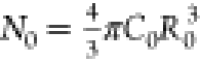 is the number of acceptors
in a sphere
with the Förster radius, R0. This
expression corresponds to the stretched exponential decay, eq 7, with β = 1/2 and
is the number of acceptors
in a sphere
with the Förster radius, R0. This
expression corresponds to the stretched exponential decay, eq 7, with β = 1/2 and  .
.
Using eq 13, its ratio of moments Rn is given by
 |
14 |
where U(a, b, z) is the confluent hypergeometric function.38 This expression is independent of the lifetime of the donor, τD, and only depends on N0, the single fitting parameter in this case.
3.3.2. Fixed-Shell Distribution
This model distribution corresponds to all relevant acceptors placed at a fixed distance a from a single donor (see Figure 1a). Let N be the average number of acceptors per donor. For different donors, the number of acceptors in the shell fluctuates, taking the values j = 0, 1,···, Nmax. We shall assume that Nmax is large and j obeys the Poisson distribution, with the probabilities given by
| 15 |
The average survival probability of an excited donor surrounded by such an acceptor shell can be written as
 |
16 |
where we assumed Nmax → ∞ in the second line. Therefore, we have
| 17 |
and, thus, the donor emission decay function for the fixed-shell distribution function is given by
 |
18 |
This model system can represent a cluster of acceptors linked to a donor. If the donor–acceptor distances within the cluster are not the same but do not exceed a certain parameter a, it can be shown that the result will be different from eq 18 only by a numerical factor ξ, i.e., a → ξa.
Introducing an average acceptor concentration, C0 = 3N/(4πa3), eq 18 can be rewritten as
 |
19 |
where N0 is the number of acceptors in a sphere of radius R0 (Förster radius) and α = R0/a. These definitions allow us to compare the decay functions for the homogeneous distribution and fixed-shell distributions for the same N0. The latter depends on the parameter α, which is inversely proportional to the acceptors’ distance to the donor within a cluster. The statistical moments of this function could not be obtained in an analytical form. However, numerical calculations show that the Rn ratio of moments does not depend on the donor lifetime τD and is entirely determined by the parameters N0 and α.37
3.3.3. 2D Homogeneous Distribution of Acceptors
Such a geometry, shown schematically in Figure 1b, was used in several experimental works to estimate the FRET parameters for QDs.39,40 Introducing a two-dimensional (2D) concentration of acceptors, cA, and using cylindrical coordinates so that
| 20 |
where h is the separation between the donor QD and the acceptor plane, the integral in eq 10 is rewritten as
 |
21 |
where
in the second line it has been assumed
that cA(ρ, ϕ) = const, b = (h/R0)2, and E4/3 denotes the exponential
integral function of order 4/3. For h ≪ R0, the second term in eq 21 can be neglected, and we get the stretched
exponential function with  . Let us mention
that experimentally estimated
values of the Förster radius for CdSe/ZnS core–shall
QDs were on the order of 10–20 nm.40,41 Inserting eq 21 into eq 11 gives the final expression
for the donor decay rate as
. Let us mention
that experimentally estimated
values of the Förster radius for CdSe/ZnS core–shall
QDs were on the order of 10–20 nm.40,41 Inserting eq 21 into eq 11 gives the final expression
for the donor decay rate as
| 22 |
where pA = πR02cA and Γ is the γ function.
| 23 |
This result was previously derived using a different approach.42
For the approximate expression of the decay function, eq 23, one can obtain an analytical expression for the statistical moments
 |
24 |
where 1F2 is the generalized hypergeometric function38 and  . We do not present here the respective
ratio of moments Rn,
calculated from eq 22, because its analytical form is cumbersome. However, one can easily
prove that this Rn ratio
does not depend on the donor lifetime, τD. (The same
applies to the Rn ratios
of the homogeneous and fixed-shell distribution.) Thus, the Rn ratio of the plane acceptor
distribution is entirely determined by the effective number of acceptors
within a circle of the Förster radius, pA.
. We do not present here the respective
ratio of moments Rn,
calculated from eq 22, because its analytical form is cumbersome. However, one can easily
prove that this Rn ratio
does not depend on the donor lifetime, τD. (The same
applies to the Rn ratios
of the homogeneous and fixed-shell distribution.) Thus, the Rn ratio of the plane acceptor
distribution is entirely determined by the effective number of acceptors
within a circle of the Förster radius, pA.
It is interesting to compare the values of R2 for different spatial distributions of acceptors. For b → 0 and large cA, eq 24 yields limcA→∞Rn=2plane ≈ 5.6, compared to the value Rn=2 ≈ 3.3 for a homogeneous 3D distribution of acceptors (β = 1/2), according to eq 14. On the other hand, for b ≫ 1, i.e., when the donor is far from the plane of acceptors, R2plane → 2, the value characteristic of a single-exponential decay, as expected.
3.3.4. 2D Homogeneous Distribution of Plasmonic Nanoparticles (NPs)
Even though the optical properties of
plasmonic nanoparticles (NPs) are obviously different from acceptor
QDs, we can apply the model presented in Section 3.3.3 to describe the EM energy transfer from
donor QDs to the NP layer. Plasmonic NPs may be seen as antennas coupled
to point emitters (QDs); however, large Ohmic losses in the metal
lead to emission quenching that suppresses strong coupling between
the antenna and the emitter, so the net result is determined by the
interplay between the near-field enhancement effect and the quenching.43 In any case, the emission decay time after a
pulsed excitation becomes shorter in the presence of plasmonic NPs.
This effect can be described by an effective decay rate γ =
γ0 + Γ, where γ0 is the spontaneous
decay rate of an isolated emitter and Γ stands for both radiation
rate enhancement and losses associated with the NPs and can be related
to the dyadic Green function.44 The latter
can be calculated analytically in the quasistatic limit (both the
NP radius, a, and the distance to the emitter, r, are much smaller than the wavelength, 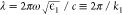 ) and expressed in terms of a multipole
expansion.43 The dipole term, dominating
at distances r ≫ a, of the
radial component of the dyadic Green function reads
) and expressed in terms of a multipole
expansion.43 The dipole term, dominating
at distances r ≫ a, of the
radial component of the dyadic Green function reads
| 25 |
where ϵm is the metal dielectric function (notice that the term in parentheses is the NP’s polarizability). The NP-induced decay rate is given by44
| 26 |
where d is the transition dipole moment of the emitter. Combining eqs 25 and 26, the NP-induced decay rate for a radially oriented emitter normalized to the spontaneous emission rate is
| 27 |
The near-field enhancement of the emission rate peaks at the localized surface plasmon resonance (LSPR) frequency determined by Re(ϵm + 2ϵ1) = 0, but apart from the LSPR, the right-hand side of eq 27 is proportional to Im(ϵm) and represents Ohmic losses, i.e., the NP acts as a PL quencher. Indeed, the PL quenching was observed experimentally for QDs placed in the vicinity of a layer of plasmonic NPs.45,46 Therefore, like acceptor QDs, the plasmonic NPs irreversibly absorb EM energy emitted by the donors. Note that the dependence of Γ on the emitter-NP distance is the same (r–6) as in the case of a donor–acceptor QD pair, eq 9, and we can introduce an effective “Förster radius” from eq 27,
| 28 |
Therefore, the expressions derived in Section 3.3.3 remain valid for the system considered here.
4. Case Studies
4.1. Case Study I—Effect of QD’s Inorganic Shell Composition
In this study, we investigated core–shell QDs with CdSe core (2.3 nm in diameter) of fixed size and different inorganic shell compositions (Table 1). First, we synthesized QDs with ZnS shells of different thicknesses using the same synthesis technique as in a previous study by Krivenkov et al.,47 and we used their solutions in hexane with a concentration of 10–6 M. Samples with ZnS shell thicknesses of 1, 3, and 5 monolayers (MLs) were used, and their extinction and PL spectra are presented in Figure 2a. We measured their PL decay kinetics at the wavelengths of the emission peaks using a TCSPC system with excitation by pulsed 400 ps laser at 532 nm wavelength, ensuring average exciton occupancy per one QD of less than 10% (Figure 2b). One can see that the PL lifetime tends to increase with an increase in shell thickness. We also calculated the Rn ratio for these PL decay kinetics and plotted it in Figure 2c. It turns out that these emitters show a non-monoexponential behavior, except for the sample with 5 monolayers (MLs) of ZnS shell. This non-monoexponential behavior can be explained by the presence of a fraction of charged QDs in the solution (see Section S4 of the SI for further discussion). The increase of the thickness of the ZnS shell to 5 MLs completely blocks the charge transfer from the QD core to the trap states and prevents the formation of the “dark fraction” with a different PL lifetime. The trend of the monoexponential behavior with the increase of the thickness of the ZnS shell is also clear in the Rn analysis by the constant decrease of R2 and R3 until reaching values close to the Rn=2 = 2 and Rn=3 = 4/3 values of the single-exponential function.
Table 1. Properties of the Samples of CdSe QDs with ZnS Shell47 Used in Case Study I and CdSe QDs with ZnS/CdS/ZnS Multicomponent Shell48 Used in Case Study I and Case Study III.
| sample | core [diameter (nm)] | shell [thickness (MLs)] | medium | concentration |
|---|---|---|---|---|
| CdSe/ZnS QD solution | CdSe [2.3] | ZnS [1] | hexane | <10–6 M |
| CdSe/ZnS QD solution | ZnS [3] | hexane | <10–6 M | |
| CdSe/ZnS QD solution | ZnS [5] | hexane | <10–6 M | |
| CdSe/ZnS/CdS/ZnS QD solution | ZnS/CdS/ZnS [1/1/1] | hexane | <10–6 M | |
| single CdSe[ZnS/CdS/ZnS] QD in PMMA | PMMA | <1 μm–2 |
Figure 2.

Investigation of the effect of shell thickness and environment on the PL decay kinetics for different samples. (a) Extinction (dash-dot lines) and PL spectra (solid lines) of CdSe/ZnS QDs with different thicknesses of ZnS layer (1 ML—black lines, 3 MLs—red lines, 5 MLs—blue lines). (b) PL decay kinetics of CdSe/ZnS QDs with different thicknesses of ZnS layer (1 ML—black dots, 3 MLs—red dots, 5 MLs—blue dots). (c) Experimental Rn ratios for CdSe/ZnS QDs with different thicknesses of ZnS layer (1 ML—black squares, 3 MLs—red circles, 5 MLs—triangles). (d) Extinction (blue dash-dot line) and PL spectra (solid red line) of CdSe/ZnS/CdS/ZnS QDs. (e) PL decay kinetics of CdSe/ZnS/CdS/ZnS QDs in solution (black dots) and in poly(methyl methacrylate) (PMMA) matrix (red dots). (f) Experimental Rn ratios for CdSe/ZnS/CdS/ZnS QDs in solution (black squares) and in PMMA matrix (red circles).
Another way to increase the charge localization in the QD core is using the multicomponent shell that contains 1 ML of ZnS, 1 ML of CdS, and another 1 ML of ZnS. As shown in the literature, such a composition leads to a drastic increase of the PL QY up to 100%.48 We used such QDs with the core size of 2.3 nm; their extinction and PL spectra are presented in Figure 2d. We measured the PL decay kinetics of the solution of QDs (black dots in Figure 2e) and calculated the Rn ratios (black squares in Figure 2f). One can see that the PL decay kinetics is purely monoexponential, which probably is related to the strong localization of the charge inside the core due to the complex composition of the inorganic shell. We also measured the PL decay kinetics of a single QD in a PMMA matrix (red dots in Figure 2e). To do that, we fabricated a 10 nm thick PMMA film with QDs inside, following the procedure from the study of Krivenkov et al.49 and used a MicroTime 200 fluorescent microscope with a 100 ps excitation source at the 485 nm wavelength (details of the procedure of preparation and thickness measurements of QD in PMMA films and single-particle measurements are provided in Sections S2 and S3 of the SI).
One can see from Figure 2 that the lifetime decreased from 31 to 15 ns, but the PL decay kinetics are still close to monoexponential as confirmed by the Rn analysis (red dots in Figure 2f). The lifetime decrease corresponds to the increasing amount of defects in the QDs due to their interaction with the PMMA matrix and the probable loosing of some ligands during the deposition. However, the composite shell structure prevents the transfer and long-living trapping of the charge from the core of QD to the QD surface. Thus, the charging of the QD core was suppressed during the measurement time (30 s), and measured QD emission was almost always a result of radiative recombination of an exciton but not of radiative recombination of a trion (charged exciton). These conditions lead to the decrease of the PL QY and PL lifetime but not to the formation of the short-living component in the PL decay kinetics. Thus, the proposed method of analysis of PL decay kinetics can be indicative of the presence of a dark fraction in the QD ensemble without making additional measurements of the quantum yield.
4.2. Case Study II—FRET in CdSe QD Ensembles
In this study, we investigated two different ensembles of QDs showing the emission peaks at 520 and 610 nm, respectively (see Figure 3a, the estimated average size of the CdSe core was 2.5 and 5 nm, respectively). The idea was to study the influence of larger (acceptor) QDs on the emission kinetics of the smaller (donor) ones, mediated by nonradiative energy transfer mechanisms such as FRET, previously investigated in a number of works.50−52 The core-only CdSe QDs, capped with sodium bis(2-ethylhexyl)sulfosuccinate (AOT) organic ligand shell, were either deposited as “monosize” or mixed composite films embedded in PMMA. Their synthesis followed the procedures reported in previous studies.27,53 Using TCSPC, PL kinetics were acquired at the wavelength of the donor QD emission, 520 nm; they are presented in Figure 3b. One can observe that all kinetics show a non-monoexponential behavior, which can be understood by admitting the existence of trap states leading to a fraction of charged QDs even in solution. Furthermore, the PMMA environment yields an additional effect in the shape and lifetime of the kinetics, as understood in Case study I.
Figure 3.

Experimental results for CdSe QD ensembles: (a) Absorption and normalized PL spectra for two species of CdSe QDs of different mean size with the emission peaks at 520 (donors) and 610 nm (acceptors), respectively, in a toluene solution; (b) PL decay kinetics for three different CdSe QD systems: (i) nominally monosize ensemble of QDs dispersed in a PMMA film (black dots), (ii) two-size ensemble of QDs dispersed in a PMMA film (red dots); (c) Rn ratios calculated for the experimental kinetics of panel (b).
The addition of the 5 nm sized acceptor QDs changes the overall shape of the decay kinetics of the 2.5 nm sized donor QDs, showing a clear decrease of the decay time. This effect can be attributed to the opening of a new decay channel of excited donors via FRET. The analysis of the Rn ratios of these kinetics, shown in Figure 3c, demonstrates a noticeable increase of Rn=2 and Rn=3 in the QD two-size mixed ensemble compared with the donor-only (nominally monosize QDs) one, with the introduction of the FRET channel.
To compare the Rn ratios for different theoretical decay functions discussed in Section 3, we carried out simulations of the experiment-based histograms of the Rn ratios; the results are shown in Figure 4. One can observe that the homogeneous distribution decay function is the one that worse fits the experimental points, constantly overestimating Rn≥2, whereas the double-exponential function and the fixed-shell distribution decay function reproduce the experimental data quite well. Regarding the donor–acceptor QD mixture embedded in a PMMA matrix, Figure 4b, although both fits shown by black and green dashed lines are good, the fixed-shell distribution decay function looks slightly better for small n. Both functions have just two adjustable parameters, but those of the fixed-shell distribution, the effective number of acceptors per donor, N0, and the ratio of the Förster radius and the average acceptor–donor distance in units of R0, α, appear more natural in the context of a system where FRET and QD clustering are possible.
Figure 4.

Simulation of the experimental data for the two CdSe QD ensembles of Figure 3 in terms of the Rn ratios calculated for three different models: (1) a phenomenological double-exponential function (black dashed lines), (2) stretched exponential decay function for β = 1/2 corresponding to a homogeneous distribution of acceptors in space (red dashed lines), and (3) the fixed-shell acceptor distribution decay function (green dashed lines). Two panels represent different QD ensembles: (a) Nominally monosize QDs dispersed in a PMMA film; (b) mixture of 2.5 and 5 nm QDs dispersed in a PMMA film.
4.3. Case Study III—QDs Near a Layer of Plasmonic NPs
In this study, we investigated PL decay kinetics in a layer of QDs covered with a PMMA spacer of controlled thickness and overcoated with a layer of silver plasmonic nanoparticles (NPs). We used the same core–multishell CdSe/ZnS/CdS/ZnS QDs as in Case Study I; their extinction and PL spectra are presented in Figure 2d. A water solution of 12 nm silver nanospheres was obtained by reduction of silver nitrate with sodium borohydride in the presence of poly(vinylpyrrolidone) (Mw = 10 kDa) described in a previous work.49 Silver NPs were applied by dropping the water solution to the surface of the PMMA film covering the QD layer, so first, we measured the effect of water on the PL decay kinetics of QDs (red symbols in Figure 5a,b). As compared to bare QDs in PMMA (black symbols), this led to a decrease of the PL lifetime and an increase of R2. It can be explained by the water-induced formation of defects that increased the nonradiative recombination rate.
Figure 5.

Effect of the layer of silver plasmonic nanospheres on the PL decay kinetics of a single CdSe/ZnS/CdS/ZnS QD localized in PMMA matrix for different PMMA spacer thicknesses, as indicated: (a) QD PL decay kinetics, (b) Rn ratios evaluated from the experimental data and theoretical distribution according to the model of Section 3.3.3 (β = 1/3) with other parameters (defined in Section 3.3.3) as indicated on the plot.
Then, we investigated the effect of the layer of silver NPs on the QD PL decay kinetics (green, cyan, and blue curves in Figure 5a) and found a strong decrease in the PL lifetime, which was previously explained by the electromagnetic (i.e., Förster-type) energy transfer from QD excitons to the silver NPs.49 This was achieved using PMMA spacers with precisely controlled thicknesses (see the SI for details). The thinner the layer of PMMA between QDs and silver NPs, the shorter the QD-NPs distance and shorter QD PL lifetime. Moreover, in this case, we also found a strong change in the Rn ratios completely different from the single-exponential behavior seen for the QDs in solution (Figure 2b,c).
Figure 5b presents the Rn ratios calculated from the experimentally measured kinetics of Figure 5a (symbols) and those obtained by eq 24 (presented by dashed lines, although, of course, they correspond only to discrete values of n). The dimensionless concentration, pA, was kept constant for the three samples, while b = (h/R0)2 was treated as a fitting parameter. Using the Drude model parameters for Ag from the literature,54 we estimate R̃0 ≈ 25 nm for the NPs used in this study at λ = 560 nm. The fitted values correspond to R0, that is, roughly 2–3 times larger than the above theoretical estimate from eq 28. This discrepancy might be attributed to deviations from the plane distribution of NPs and their partial agglomeration. (Notice that the PL kinetics were acquired from a single QD; thus, fluctuations in its position with respect to the quenchers were quite possible.) Nevertheless, the tendency with the decreasing h (stronger energy transfer) is well reproduced by the model, although the “fitting” is imperfect for the case of h = 10 nm (and even worse for h = 5 nm, not shown in the figure). The latter can be understood by the “proximity effect” for the lowest spacer thicknesses when the emitter–quencher separation becomes smaller than the NP size and the dipole approximation eq 25 becomes insufficient.
5. Discussion and Conclusions
We presented a new approach to the analysis of PL decay kinetics in ensembles of QDs (or other point emitters) using the ratios of their statistical moments, Rn, defined by eq 3. It has clear advantages over the standard method of fitting decay curves with a certain predefined function containing a number of parameters. The calculation of the statistical moments is model-free and numerically robust, and the comparison with different physical models takes place based on the conveniently defined Rn ratios. We showed its potential for use in different QD systems as a simple and efficient tool for monitoring the effects of the QD inorganic shell, QDs’ clustering, or environment that introduced FRET-type de-excitation channels. The Rn ratios for several theoretical decay functions were obtained, such as the single- and double-exponential functions and the Kohlrausch function for β = 1/2 (corresponding to FRET in the presence of a homogeneous spatial distribution of acceptors), the fixed-shell, and 2D acceptor distribution decay functions introduced in this work. It is easy to see from the Rn dependence upon n (Figure 2) that the decay kinetics of well-separated QDs with multilayer inorganic shells are purely single-exponential, which is probably because of elimination of traps that could lead to interference of slower relaxation processes. (For the sake of completeness, let us mention that the sometimes used Becquerel decay function55 that takes into account complicated trapping and re-trapping processes occurring in phosphors26 is not suitable for the proposed method because the integrals defining higher-order moments do not converge for t → ∞.)
The moment analysis is particularly suitable when emitter relaxation channels related to electromagnetic energy transfer to other species are present in the system. In our Case Study II, the Rn ratio for experimental decay kinetics of CdSe has shown a considerable difference in its variation with n when analyzing the PL decay kinetics recorded at the peak of the donor emission band for the two-size mixture of CdSe QDs embedded in PMMA, which we interpreted as a consequence of the FRET mechanism. These Rn values fit well the fixed-shell spatial distribution of acceptors modeling their clustering around a donor QD. In principle, one can estimate the Förster radius from the fitting parameters of this distribution.37
Furthermore, the value of R2 is clearly distinctive between different spatial distributions of acceptors, as noticed at the end of Section 3.3.3. The tendency of increasing R2 values as the spacer thickness diminishes in the Case Study III is in line with the theoretical prediction for the EM energy transfer from an excited donor to the plane of plasmonic NPs acting as quenchers. Only the case of the thinnest spacer (Figure 5b) is not covered by the theory presented in Section 3.3.3, but it can be accounted for the high proximity of the emitter–quencher pair leading to interactions beyond the dipole–dipole approximation. Indeed, the quadrupole term in the dyadic Green function, scaling as r–8, becomes important and even dominating.43 It is easy to show by a calculation similar to eq 21 that the Kohlrausch term has β = 1/4 in this case. We verified that R2 increases and the ratio R3/R2 becomes smaller (i.e., the Rn curve becomes steeper) as β decreases from 1 to ≈0.2, so the case β = 1/4 describes the Rn distribution for h = 10 nm in Figure 5b better. Therefore, the model described in Section 3.3.3, with the adaptation to plasmonic acceptors presented in Section 4.3, provides a good qualitative understanding of this system.
To conclude, with the study here presented, we hope to introduce the Rn ratio analysis as a new method for analyzing PL kinetics in different light-emitting systems, which is computationally efficient compared to the conventional PL curve-fitting and rather informative in terms of the environment and details of the emitters. In particular, the developed approach paves the way to a more accurate characterization and improvement of the properties of QDs and QD-based materials essential for their promising optoelectronic applications.
Acknowledgments
The authors are indebted to Eduardo Nunes Pereira (University of Minho), who passed away while this work was in progress. J.R.M. wishes to acknowledge helpful discussions with Willem L. Vos (University of Twente, the Netherlands). M.I.V. wishes to thank the hospitality of the Donostia International Physics Centre (DIPC), Spain. Funding from the Portuguese Foundation for Science and Technology (FCT) in the framework of the Strategic Financing UID/FIS/04650/2020 is acknowledged. V.K. acknowledges funding from the European Union’s Horizon 2020 research and innovation programme under the Marie Sklodowska-Curie grant agreement 101025664 (QESPEM). Y.P.R. acknowledges funding from the Basque Government for Consolidated groups of the Basque University (Grant IT 1526-22) and Basic and/or Applied Research Projects (Grant PIBA-2021-0026). Part of this work dealing with the synthesis of CdSe/ZnS and CdSe/ZnS/CdS/ZnS quantum dots was supported by the Russian Science Foundation (Grant 18-19-00588).
Supporting Information Available
The Supporting Information is available free of charge at https://pubs.acs.org/doi/10.1021/acs.jpcc.2c06134.
Derivation of the stretched exponential function, leading to the expression in eq 10; fabrication of QD in PMMA thin films by spin-coating using a Model KW-4A Spin-Coater; single-particle measurement using photon correlation technique; notes about dark fraction in QDs on (i) how it is related to the fluorescence intermittency (blinking) of QDs, (ii) how it affects the PL decay kinetics, and (iii) how one can use the statistical analysis to identify the formation of a dark fraction in a QD ensemble without measurement of QY and single-particle measurements (PDF)
The authors declare no competing financial interest.
Supplementary Material
References
- Jones M.; Scholes G. D. On the Use of Time-Resolved Photoluminescence as a Probe of Nanocrystal Photoexcitation Dynamics. J. Mater. Chem. 2010, 20, 3533–3538. 10.1039/c000165a. [DOI] [Google Scholar]
- Song J. H.; Jeong S. Colloidal Quantum Dot Based Solar Cells: from Materials to Devices. Nano Convergence 2017, 4, 1844 10.1186/s40580-017-0115-0. [DOI] [PMC free article] [PubMed] [Google Scholar]
- Rakovich Y. P.; Donegan J. F.; Vasilevskiy M. I.; Rogach A. L. Anti-Stokes Cooling in Semiconductor Nanocrystal Quantum Dots: A Feasibility Study. Phys. Status Solidi A 2009, 206, 2497–2509. 10.1002/pssa.200925052. [DOI] [Google Scholar]
- Saha J.; Datta Roy A.; Dey D.; Bhattacharjee D.; Arshad Hussain S. Role of Quantum Dot in Designing FRET Based Sensors. Mater. Today Proc. 2018, 5, 2306–2313. 10.1016/j.matpr.2017.09.234. [DOI] [Google Scholar]
- Cardoso dos Santos M.; Algar W. R.; Medintz I. L.; Hildebrandt N. Quantum Dots for Förster Resonance Energy Transfer (FRET). TrAC, Trends Anal. Chem. 2020, 125, 115819 10.1016/j.trac.2020.115819. [DOI] [Google Scholar]
- Burdov V. A.; Vasilevskiy M. I. Exciton-Photon Interactions in Semiconductor Nanocrystals: Radiative Transitions, Non-Radiative Processes and Environment Effects. Appl. Sci. 2021, 11, 497 10.3390/app11020497. [DOI] [Google Scholar]
- Bodunov E. N.; Simões Gamboa A. L. Kinetics of Photoluminescence Decay of Colloidal Quantum Dots: Nonexponential Behavior and Detrapping of Charge Carriers. J. Phys. Chem. C 2018, 122, 10637–10642. 10.1021/acs.jpcc.8b02779. [DOI] [Google Scholar]
- Shim T.; Lee M.; Kim S.; Sung J.; Rhee B. K.; Kim D.; Kim H.; Yoon K. B. Photoluminescence Decay Lifetime Measurements of Hemicyanine Derivatives of Different Alkyl Chain Lengths. Mater. Sci. Eng., C 2004, 24, 83–85. 10.1016/j.msec.2003.09.050. [DOI] [Google Scholar]
- Zhao F.; Wang X.; Chen H.; Luo J.. Nanowires; Hashim A., Ed.; IntechOpen: Rijeka, 2011; Chapter 9. [Google Scholar]
- Xu F.; Haughn C. R.; Ma X.; Doty M. F.; Cloutier S. G. Charge-Transfer Dynamics in Multilayered PbS and PbSe Quantum Dot Architectures. Appl. Phys. Lett. 2014, 104, 051112 10.1063/1.4863953. [DOI] [Google Scholar]
- Speirs M. J.; Balazs D. M.; Fang H. H.; Lai L. H.; Protesescu L.; Kovalenko M. V.; Loi M. A. Origin of the Increased Open Circuit Voltage in PbS-CdS Core-Shell Quantum Dot Solar Cells. J. Mater. Chem. A 2015, 3, 1450–1457. 10.1039/C4TA04785K. [DOI] [Google Scholar]
- Stroyuk O.; Raevskaya A.; Gaponik N.; Selyshchev O.; Dzhagan V.; Schulze S.; Zahn D. R. Origin of the Broadband Photoluminescence of Pristine and Cu+/Ag+-Doped Ultrasmall CdS and CdSe/CdS Quantum Dots. J. Phys. Chem. C 2018, 122, 10267–10277. 10.1021/acs.jpcc.8b02337. [DOI] [Google Scholar]
- Huang J.; Gatty M. G.; Xu B.; Pati P. B.; Etman A. S.; Tian L.; Sun J.; Hammarström L.; Tian H. Covalently Linking CuInS2 Quantum Dots with a Re Catalyst by Click Reaction for Photocatalytic CO2 Reduction. Dalton Trans. 2018, 47, 10775–10783. 10.1039/C8DT01631C. [DOI] [PubMed] [Google Scholar]
- Yao J.-S.; Ge J.; Han B.-N.; Wang K.-H.; Yao H.-B.; Yu H.-L.; Li J.-H.; Zhu B.-S.; Song J.-Z.; Chen C.; et al. Ce3+-Doping to Modulate Photoluminescence Kinetics for Efficient CsPbBr3 Nanocrystals Based Light-Emitting Diodes. J. Am. Chem. Soc. 2018, 140, 3626–3634. 10.1021/jacs.7b11955. [DOI] [PubMed] [Google Scholar]
- Wijaya H.; Darwan D.; Lim K. R. G.; Wang T.; Khoo K. H.; Tan Z. K. Large-Stokes-Shifted Infrared-Emitting InAs-In(Zn)P-ZnSe-ZnS Giant-Shell Quantum Dots by One-Pot Continuous-Injection Synthesis. Chem. Mater. 2019, 31, 2019–2026. 10.1021/acs.chemmater.8b05023. [DOI] [Google Scholar]
- O’Neil M.; Marohn J.; McLendon G. Dynamics of Electron-Hole Pair Recombination in Semiconductor Clusters. J. Phys. Chem. A 1990, 94, 4356–4363. 10.1021/j100373a089. [DOI] [Google Scholar]
- Soloviev V. N.; Eichhöfer A.; Fenske D.; Banin U. Size-Dependent Optical Spectroscopy of a Homologous Series of CdSe Cluster Molecules. J. Am. Chem. Soc. 2001, 123, 2354–2364. 10.1021/ja003598j. [DOI] [PubMed] [Google Scholar]
- Fisher B. R.; Eisler H. J.; Stott N. E.; Bawendi M. G. Emission Intensity Dependence and Single-Exponential Behavior in Single Colloidal Quantum Dot Fluorescence Lifetimes. J. Phys. Chem. B 2004, 108, 143–148. 10.1021/jp035756+. [DOI] [Google Scholar]
- Schöps O.; Le Thomas N.; Woggon U.; Artemyev M. V. Recombination Dynamics of CdTe/CdS Core-Shell Nanocrystals. J. Phys. Chem. B 2006, 110, 2074–2079. 10.1021/jp0557013. [DOI] [PubMed] [Google Scholar]
- Mongin C.; Moroz P.; Zamkov M.; Castellano F. N. Thermally Activated Delayed Photoluminescence from Pyrenyl-Functionalized CdSe Quantum Dots. Nat. Chem. 2018, 10, 225–230. 10.1038/nchem.2906. [DOI] [PubMed] [Google Scholar]
- Bodunov E. N.; Antonov Y. A.; Simões Gamboa A. L. On the Origin of Stretched Exponential (Kohlrausch) Relaxation Kinetics in the Room Temperature Luminescence Decay of Colloidal Quantum Dots. J. Chem. Phys. 2017, 146, 114102 10.1063/1.4978396. [DOI] [PubMed] [Google Scholar]
- Bodunov E. N.; Danilov V. V.; Panfutova A. S.; Simões Gamboa A. L. Room-Temperature Luminescence Decay of Colloidal Semiconductor Quantum Dots: Nonexponentiality Revisited. Ann. Phys. 2016, 528, 272–277. 10.1002/andp.201500350. [DOI] [Google Scholar]
- Bodunov E. N.; Simões Gamboa A. L. Luminescence Decay of Colloidal Quantum Dots and Stretched Exponential (Kohlrausch) Relaxation Function. Semiconductors 2018, 52, 587–589. 10.1134/S1063782618050044. [DOI] [PubMed] [Google Scholar]
- Simões Gamboa A. L.; Bodunov E. N. In Functions for Describing Nonexponential Photoluminescence Decay Kinetics in Semiconductor Nanocrystals, 2022 International Conference Laser Optics (ICLO); IEEE, 2022.
- Berberan-Santos M. N.; Bodunov E. N.; Valeur B. Mathematical Functions for the Analysis of Luminescence Decays with Underlying Distributions: 2. Becquerel (Compressed Hyperbola) and Related Decay Functions. Chem. Phys. 2005, 317, 57–62. 10.1016/j.chemphys.2005.05.026. [DOI] [Google Scholar]
- Bernardo C.; Moura I.; Fernández Y. N.; Nunes-Pereira E. J.; Coutinho P. J.; Garcia A. M.; Schellenberg P.; Belsley M.; Costa M. F.; Stauber T.; Vasilevskiy M. I. Energy Transfer Via Exciton Transport in Quantum Dot Based Self-Assembled Fractal Structures. J. Phys. Chem. C 2014, 118, 4982–4990. 10.1021/jp411456m. [DOI] [Google Scholar]
- Zhou Y.; Zhuang X. Robust Reconstruction of the Rate Constant Distribution using the Phase Function Method. Biophys. J. 2006, 91, 4045–4053. 10.1529/biophysj.106.090688. [DOI] [PMC free article] [PubMed] [Google Scholar]
- Berberan-Santos M. N.; Bodunov E. N.; Valeur B. Mathematical Functions for the Analysis of Luminescence Decays with Underlying Distributions 1. Kohlrausch Decay Function (Stretched Exponential). Chem. Phys. 2005, 315, 171–182. 10.1016/j.chemphys.2005.04.006. [DOI] [Google Scholar]
- Papoulis A.Probability, Random Variables, and Stochastic Processes; McGraw Hill, 1984. [Google Scholar]
- Van Driel A. F.; Nikolaev I. S.; Vergeer P.; Lodahl P.; Vanmaekelbergh D.; Vos W. L. Statistical Analysis of Time-Resolved Emission from Ensembles of Semiconductor Quantum Dots: Interpretation of Exponential Decay Models. Phys. Rev. B 2007, 75, 035329 10.1103/PhysRevB.75.035329. [DOI] [Google Scholar]
- Förster T. Experimentelle und Theoretische Untersuchung des Zwischenmolekularen Übergangs von Elektronenanregungsenergie. Z. Naturforsch., A: J. Phys. Sci. 1949, 4, 321–327. 10.1515/zna-1949-0501. [DOI] [Google Scholar]
- Drake J. M.; Klafter J.; Levitz P. Chemical and Biological Microstructures as Probed by Dynamic Processes. Science 1991, 251, 1574–1579. 10.1126/science.2011737. [DOI] [PubMed] [Google Scholar]
- Förster T. Zwischenmolekulare Energiewanderung und Fluoreszenz. Ann. Phys. 1948, 437, 55–75. 10.1002/andp.19484370105. [DOI] [Google Scholar]
- Farinha J. P. S.; Martinho J. M. G. Resonance Energy Transfer in Polymer Nanodomains. J. Phys. Chem. C 2008, 112, 10591–10601. 10.1021/jp8016437. [DOI] [Google Scholar]
- If the donor QD is approximated by a point
dipole embedded in a medium with the relative permittivity ϵ1, τD is the inverse of the spontaneous emission
rate, γ0:6
where d is the transition dipole moment and
 .
. - Martins J. R.Study of the Förster Resonance Energy Transfer in Ensembles of Colloidal PbS Quantum Dots, emitting in the Near-Infrared Spectral Range. M.Sc. Thesis, University of Minho, 2020. [Google Scholar]
- Handbook of Mathematical Functions, Abramowitz M.; Stegun I. A., Eds.; Dover: New York, 1972. [Google Scholar]
- Lunz M.; Bradley A. L.; Gerard V. A.; Byrne S. J.; Gun’ko Y. K.; Lesnyak V.; Gaponik N. Concentration Dependence of Förster Resonant Energy Transfer Between Donor and Acceptor Nanocrystal Quantum Dot Layers: Effect of Donor-Donor Interactions. Phys. Rev. B 2011, 83, 115423 10.1103/PhysRevB.83.115423. [DOI] [Google Scholar]
- Shafiei F.; Ziama S. P.; Curtis E. D.; Decca R. S. Measurement of the Separation Dependence of Resonant Energy Transfer Between CdSe/ZnS Core/Shell Nanocrystallite Quantum Dots. Phys. Rev. B 2011, 84, 075301 10.1103/PhysRevB.84.075301. [DOI] [Google Scholar]
- Mork A. J.; Weidman M.; Prins F.; Tisdale W. Magnitude of the Förster Radius in Colloidal Quantum Dot Solids. J. Phys. Chem. C 2014, 118, 13920–13928. 10.1021/jp502123n. [DOI] [Google Scholar]
- Wolber P.; Hudson B. An Analytic Solution to the Förster Energy Transfer Problem in Two Dimensions. Biophys. J. 1979, 28, 197–210. 10.1016/S0006-3495(79)85171-1. [DOI] [PMC free article] [PubMed] [Google Scholar]
- Delga A.; Feist J.; Bravo-Abad J.; Garcia-Vidal F. J. Quantum Emitters Near a Metal Nanoparticle: Strong Coupling and Quenching. Phys. Rev. Lett. 2014, 112, 253601 10.1103/PhysRevLett.112.253601. [DOI] [PubMed] [Google Scholar]
- Novotny L.; Hehct B.. Principles of Nano-Optics; Cambridge University Press, 2012. [Google Scholar]
- Matsumoto Y.; Kanemoto R.; Itoh T.; Nakanishi S.; Ishikawa M.; Biju V. Photoluminescence Quenching and Intensity Fluctuations of CdSe-ZnS Quantum Dots on an Ag Nanoparticle Film. J. Phys. Chem. C 2008, 112, 1345–1350. 10.1021/jp076659+. [DOI] [Google Scholar]
- Lunz M.; Zhang X.; Gerard V. A.; Gunko Y. K.; Lesnyak V.; Gaponik N.; Susha A. S.; Rogach A. L.; Bradley A. L. Effect of Metal Nanoparticle Concentration on Localized Surface Plasmon Mediated Foerster Resonant Energy Transfer. J. Phys. Chem. C 2012, 116, 26529–26534. 10.1021/jp309660s. [DOI] [Google Scholar]
- Krivenkov V.; Samokhvalov P.; Zvaigzne M.; Martynov I.; Chistyakov A.; Nabiev I. Ligand-Mediated Photobrightening and Photodarkening of CdSe/ZnS Quantum Dot Ensembles. J. Phys. Chem. C 2018, 122, 15761–15771. 10.1021/acs.jpcc.8b04544. [DOI] [Google Scholar]
- Linkov P.; Samokhvalov P.; Vokhmintsev K.; Zvaigzne M.; Krivenkov V. A.; Nabiev I. Optical Properties of Quantum Dots with a Core–Multishell Structure. JETP Lett. 2019, 109, 112–115. 10.1134/S0021364019020103. [DOI] [Google Scholar]
- Krivenkov V.; Dyagileva D.; Samokhvalov P.; Nabiev I.; Rakovich Y. Effect of Spectral Overlap and Separation Distance on Exciton and Biexciton Quantum Yields and Radiative and Nonradiative Recombination Rates in Quantum Dots Near Plasmon Nanoparticles. Ann. Phys. 2020, 532, 2000236 10.1002/andp.202000236. [DOI] [Google Scholar]
- Crooker S. A.; Hollingsworth J. A.; Tretiak S.; Klimov V. I. Spectrally Resolved Dynamics of Energy Transfer in Quantum-Dot Assemblies: Towards Engineered Energy Flows in Artificial Materials. Phys. Rev. Lett. 2002, 89, 186802 10.1103/PhysRevLett.89.186802. [DOI] [PubMed] [Google Scholar]
- Franzl T.; Klar T. A.; Scheitinger S.; Rogach A. L.; Feldmann J. Exciton Recycling in Graded Gap Nanocrystal Structures. Nano Lett. 2004, 4, 1599–1603. 10.1021/nl049322h. [DOI] [Google Scholar]
- Lunz M.; Bradley A. L.; Chen W.-Y.; Gerard V. A.; Byrne S. J.; Gun’ko Y. K.; Lesnyak V.; Gaponik N. Influence of Quantum Dot Concentration on Förster Resonant Energy Transfer in Monodispersed Nanocrystal Quantum Dot Monolayers. Phys. Rev. B 2010, 81, 205316 10.1103/PhysRevB.81.205316. [DOI] [Google Scholar]
- Fontes Garcia A. M.; Fernandes M. S.; Coutinho P. J. CdSe/TiO2 Core-shell Nanoparticles produced in AOT Reverse Micelles: Applications in Pollutant Photodegradation using Visible Light. Nanoscale Res. Lett. 2011, 6, 426 10.1186/1556-276X-6-426. [DOI] [PMC free article] [PubMed] [Google Scholar]
- Yang H. U.; D’Archangel J.; Sundheimer M. L.; Tucker E.; Boreman G. D.; Raschke M. B. Optical Dielectric Function of Silver. Phys. Rev. B 2015, 91, 235137 10.1103/PhysRevB.91.235137. [DOI] [Google Scholar]
- Becquerel E.La Lumière, Ses Causes Ses Effets; Firmin Didot: Paris, 1867; Vol. 1. [Google Scholar]
Associated Data
This section collects any data citations, data availability statements, or supplementary materials included in this article.