

Abstract
Background
Epidural anaesthesia is a Percutaneous Procedure (PP) which plays a crucial role in surgical procedures, where accurate needle insertion is still challenging. The objective of this work is to present a Tuohy needle path planning, which allows an anaesthesiologist to drive semiautonomously, with the assistance of a teleoperated robot, the tip of the needle during this PP.
Methods
We capture, analysed and modelled the anaesthetist hands' motion during the execution of this procedure, by synthetising, programing and simulating a parametrised and normalised kinematic constrains dependent on an insertion variable in a virtual robot.
Results
Two preoperative path planning models were obtained, which provide a teleoperated robot with kinematic constraints to semiautonomously drive a Tuohy needle in the epidural anaesthesia procedure.
Conclusions
A semiautonomous robot can assist in the execution of this PP using the kinematic constraints obtained from the study of the movement of a specialist's hands.
Keywords: epidural anaesthesia procedure, needle path planning, percutaneous procedure, semiautonomous robot
1. INTRODUCTION
Percutaneous Procedures (PPs) play a crucial role in clinics and hospitals as part of medical diagnosis and many other medical treatments. In PPs it is necessary to insert a needle into soft tissue and to place it accurately within a specific organ or tissue of a patient. 1 In recent years, research has been developed to use robots to assist in the execution of some of these procedures. Some examples of these developments are: (1) suturing, 2 , 3 , 4 (2) brain biopsies, 5 (3) brachytherapy, 1 , 6 , 7 (4) percutaneous cholecystostomy 8 and (5) nerve block. 9 , 10 , 11 In this context, one of the procedures in nerve block which can be robot‐assisted, is the Epidural Anaesthesia Procedure (EAP). Epidural Anaesthesia Procedure is an invasive procedure, which requires an anaesthesiologist to blindly insert a Tuohy needle into a patient, driving it through an intervertebral space, which is restricted by two vertebrae and is formed by six soft tissues, to place the tip of this needle at a point in the Epidural Space (ES) using only their ability to feel the reaction forces of the puncture surgical device and tissues through their hands. Figure 1 presents a simplified schematic of the spinal anatomy.
FIGURE 1.

A simplified schematic of both the lumbar vertebrae anatomy and the Tuohy needle placement in the epidural anaesthesia procedure
During the execution of this procedure, the anaesthetist must create a mental image of the internal anatomical structures of the patient from feeling these forces, since he/she must be able to recognise skin, fatty tissue, muscle, the supraspinous ligament, the interspinous ligament, the ligamentum flavum, the vertebrae and the ES. The main negative consequences for the patient reported in the literature due to accidental puncture during the performance of EAP are bruising from repeated needle insertion, 12 extreme headache due to loss of cerebrospinal fluid, 13 , 14 and injuries to the neural structure of the patient, resulting in loss of some central nervous system function. 15 , 16 , 17 For these reasons, robotic assistance in this procedure is feasible to control accurately the Tuohy needle motion through an optimal needle path, along with the ability to feel the change in resistance as the needle advances through these tissues, determining the precision of needle placement and the success of the procedure.
In the literature, there are some technological developments related to robot‐assisted nerve block procedures, using the teleoperation scheme. In this scheme, the surgeon is in complete control of the robot's actions during the execution of the surgical procedure by entering control commands into a Human‐Machine Interface (HMI), where the physician remotely gives the control commands with instrumented devices, such as joysticks, mechanisms, sliders, etc., while the robot executes the actions corresponding to each of these commands. 18 In this context, Alkhatib et al. 19 used the teleoperation control scheme for ultrasound‐guided regional anaesthesia procedure and presented a geometric method that controls the movement of a rigid needle by describing the end‐effector position of a 7‐Degrees‐of‐Freedom (DoF) robot (Franka Emika robot, Franka Emika, Munich, Germany). This geometric method considers the restrictions of the remote centre of motion. Similarly, Tighe et al. 9 used the da Vinci surgical robot (Intuitive Surgical, Sunnyvale, CA) to perform nerve blocks and perineural catheter placement. In this study, one of the da Vinci robot arms was used to position and fix an ultrasonic sensor on the surface of an ultrasonic phantom tissue, while another arm was used to grasp and drive a Tuohy needle into this phantom tissue. They reported that some movements completed with the human hand in conventional procedures were not easy to mimic by the robotic grasper, because of the advanced teleoperation skills and dexterity required to complete the procedure, especially in rotational movements. Another similar study was presented by Morse et al., 10 who addressed robot‐assisted nerve blocks guided by ultrasound images, where an anaesthesiologist carried out 20 experiments on an ultrasound phantom tissue, with no previous experience or training in the use of the robotic system called Magellan. The experiments consisted of driving the needle from a resting position to the appropriate insertion position, and finally to a simulated nerve within the phantom. Lastly, Cleary et al., 11 adapted a robot that was originally developed to assist in the percutaneous renal access procedure with fluoroscopic guidance, 20 This robot's end‐effector has two active DoF, and a needle attached. Using a joystick, both insertion and retraction of the needle can be controlled by an anaesthesiologist remotely. However, the difficulty in commanding or teleoperating these robotic systems is notorious, due to the precise movements required to guide the needle safely through the anatomical structures of the patient.
The objective of this article is to present a proof of concept of needle path planning in the context of semiautonomy and robotic teleoperation applied to the EAP. This needle path planning models how an expert anaesthetist manipulates the base of a Tuohy needle with his hands when performing six epidural anaesthesia procedures on a cadaver. The first main characteristic of this path planning is that it can be strategically adapted to the anatomical structures of a new patient from the anatomical data generated in the preoperative phase, where the initial point of the path begins at an entry point (between two vertebrae) and ends at a point within the ES, passing through an intervertebral space free of collision with any vertebra. Besides, the second main characteristic of this path planning is that it is dependent on an insertion command given directly by an anaesthetist and it can be programed in a robot as an optimal preoperative path, which allows the anaesthetist to teleoperate the robot with a kinematic constraint. Also, a secondary objective of this article is to present the semiautonomous and teleoperated robot used to drive the Tuohy needle base on the proposed path planning. In addition, to ensure the robot places the tip of the needle at a point within the ES while following the optimal path, the forces generated at the tip of the needle when it cuts the different intervertebral tissues throughout the procedure were simulated. Then, the robot was programed with an algorithm that allows it to calculate the position of the needle tip from the force it experiences, based on Esterer et al. 21 With this information, it is possible to recognise dynamically when the robot reaches the ES.
2. MATERIALS AND METHODS
Since the success of the EAP is determined by an accurate needle placement, the path of the needle throughout the procedure is crucial. This path is defined with three movements that the anaesthetist performs by manipulating the needle to find the ES, which are: (1) insertion movement, (2) extraction movement and (3) reorientation movement. In most cases, the needle may collide with a vertebra, making it necessary to remove, reorient, and reinsert it in order to find the optimal path to reach the ES. This section presents how to capture these three movements performed by an expert anaesthetist during the execution of the EAP, as well as the analysis of the anaesthetist's hands motion, and the modelling of the anaesthetist's hands motion as an optimal path which depends on an insertion variable. The objective is to programme this path in the robot as a kinematic constraint allowing the anaesthetist to teleoperate it by giving an advance command through the path. Also, we present an implementation of the force profile presented by Esterer et al. 21 where they determined the relationship between the force experienced by the needle tip with respect to its location in the intervertebral space. The idea is to ensure, with two different methods that the robot will not exceed the ES, where the first method is a kinematic approach and the second one is a dynamic approach.
2.1. Needle path planning (kinematic approach)
2.1.1. Test setup
The experimental tests were carried out in the Department of Innovation in Human Biological Material at the Faculty of Medicine, UNAM. In this study, an anaesthetist was requested (prior to signing the informed consent form) to perform six epidural anaesthesia procedures on a cadaver placed in the right lateral recumbent position (Figure 2). The first three procedures were performed in the intervertebral space bounded by the L2–L3 vertebrae and the other three in the intervertebral space bounded by the L3–L4 vertebrae. During each procedure, the movements of the anaesthesiologist's hands were captured by measuring the position and orientation of the base of a Tuohy needle, which was attached to the last link of a serial 5‐DoF mechanism called pantograph (Figure 3A).
FIGURE 2.
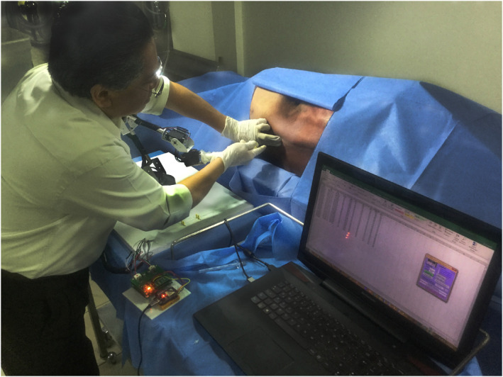
The anaesthetist is observed manipulating a Tuohy needle placed in the pantograph to perform an epidural anaesthesia procedure on a cadaver at the Department of Innovation in Human Biological Material of the Faculty of Medicine, UNAM
FIGURE 3.

(A) Serial mechanism of 5‐degrees‐of‐freedom (pantograph) with a Tuohy needle attached on its last link. (B) Diagram of the definition of the pantograph's joint rotational axes and the coordinate axes for its direct kinematics calculation
This pantograph was made up of five rigid bodies (links) connected in series by five not‐actuated rotational joints (passive joints) and was designed in close collaboration with the anaesthetist, to allow him to move the needle without any restriction of movements during the trials. Also, the needle holder was designed to be easily attached and removed from the last link of the pantograph in order to be sterilised and reused. Figure 3B shows the pantograph's mechanical configuration and its axes of rotation, along with the coordinates systems used to calculate the pantograph's forward kinematics, where {0} is the inertial coordinate system located at the base of the pantograph and {P} is the coordinate system that describes the position and the orientation of the base of the Tuohy needle. Equation (1) is used to calculate the kinematic chain until the {P} system. Where is the resulting homogeneous matrix of dimensions 4 × 4. Which contains a matrix of dimensions 3 × 3 that contains the information of the orientation of the base of the Tuohy needle in the x, y and z axes. In addition, it contains a vector of dimensions 3 × 1 that contains the coordinates (x, y, z) of the position of the base of the needle at an instant of time. Besides, to sense the five angular positions of each of the pantograph joints, five Hall‐effect rotational magnetic encoders with 0.15° of resolution (3081, POLOLU, Las Vegas, NV, USA) were used.
| (1) |
During the experimentation, the pantograph was spatially positioned close to the cadaver to allow the anaesthetist to manipulate it and record the movement of the needle correctly. Besides, during each of the six procedures, the anaesthesiologist executed a protocol that consists of palpating the spinous process of the vertebra inferior to the intervertebral space, where the procedure is going to be performed and then palpating the spinous process superior to this intervertebral space. With this, he determined the insertion point at a mid‐distance between the vertebrae that form an intervertebral space. Then, by manipulating the pantograph device, he placed the tip of the Tuohy needle at that point with an initial orientation given by the anaesthesiologist. At that time, the data recollection of the position and the orientation of the base of the Tuohy needle (system {P}), began by capturing the information of the five angular sensors at T s = 125 ms sample time, while the anaesthetist executed the EAP. The test and the data collection concluded when the anaesthetist declared that he had placed the tip of the needle within the ES of the cadaver. Then, three discrete functions x i [n], y i [n] and z i [n] were obtained from the data collected, where n is the number of the sample and i = 1, 2, 3, 4, 5 and 6 is an index of the experiment (Figure 3B).
2.1.2. Data capture
Figure 4 shows graphically each set of positions of the base of the Tuohy needle described by the discrete functions x i [n], y i [n] and z i [n] for each of the six tests. Besides, Figure 4A–C correspond to the tests performed in the L2–L3 intervertebral space, and Figure 4D–F correspond to the tests performed in the L3–L4 intervertebral space.
FIGURE 4.

Graphical results of the data collection on the movements of the base of the Tuohy needle when it was manipulated by an anaesthetist who performed six epidural anaesthesia procedures on the cadaver
2.1.3. Data analysis
Firstly, the data captured were used to establish an objective comparison of the psychomotor performance of the anaesthesiologist in the six experiments carried out. Unfortunately, previous works do not report any method to quantitatively measure the psychomotor performance of anaesthesiologists during the execution of the EAP. Therefore, motion‐based metrics were used for the assessment of technical skills and surgical performance of the six experiments performed by the anaesthesiologist. These metrics are widely used and validated to assess the psychomotor laparoscopic skills and surgical skills in PPs of surgeons. 22 , 23 , 24 , 25 For this work, five motion‐related metrics were used: total execution time, path length, Economy of Movements (EOM), total number of movements and distance between start and end points. Where the metrics: total execution time and distance between start and end points will be used in the next section to normalise and parameterise a model of the needle base motion. The results of this objective assessment of six experiments are shown in Table 1.
TABLE 1.
Numerical analysis of the experimental results
| Test | Total time of execution (s) | Path length (mm) | EOM (%) | Number of movements | Distance between the start and end points (mm) |
|---|---|---|---|---|---|
| 1 | 15.00 | 259.1 | 0.00203 | 46 | 24.05 |
| 2 | 19.12 | 197.0 | 0.00406 | 54 | 17.02 |
| 3 | 6.37 | 173.6 | 0.00454 | 30 | 35.40 |
| 4 | 17.50 | 332.6 | 0.00166 | 61 | 38.80 |
| 5 | 8.37 | 131.9 | 0.00604 | 35 | 42.40 |
| 6 | 7.37 | 142.8 | 0.00262 | 33 | 31.70 |
Abbreviation: EOM, Economy of Movements.
Then, it was observed that the anaesthetist performed three tests where the needle went straight from the point of incision to a point within the ES. Besides, it was observed that the anaesthetist performed different movements in the other three tests, which are the insertion movement, the extraction movement, and the orientation movement. According to comments made by the anaesthetist, extraction movements are necessary to change the needle path when it collides with a vertebra by extracting, reorienting, and reinserting it.
For this reason, a Progressive Insertion Criterion (PIC), between consecutive insertion movements, was defined as x i [n] − x i [n−1] > 0 to select the values of n that are valid for this criterion and, in consequence, the values of the functions x i [n], y i [n] and z i [n] that represent the set of values that only contain the progressive insertion movements of the needle through the intervertebral space without collisions with any vertebra.
2.1.4. Development of a parametric and normalised model of the needle path
After selecting the values of the functions x i [n], y i [n] and z i [n] which satisfy the PIC, a linear interpolation was applied for each function x i [n] by taking the first coordinate (n initial, x i [n initial]) and the last coordinate (n final, x i [n final]) to obtain each of these functions in a continuous and linear form by using the slope‐intercept form as i = m i t + b, where the variable i defines the insertion variable of each trial, which denotes how deep is the needle throughout of the insertion procedure, the intercept value b = 0 as shown in Equation (2), and the slope m i represents the average velocity of the insertion execution (Equation 3). As a result, Figure 5A shows each linear interpolation for each trial.
FIGURE 5.

(A) Shows the evolution of the needle base insertion variable i (t) on the x‐axis for each procedure, which is the result of the linear interpolation of the discrete function x i [n]. (B) shows the evolution of the needle base orientation variable y i (t) on the y‐axis for each procedure, which is the result of curve fitting of the discrete function y i [n]. (C) shows the evolution of the needle base orientation variable z i (t) on the z‐axis for each procedure, which is the result of curve fitting of the discrete function z i [n]
Additionally, a continuous nonlinear regression curve fitting for the functions y i [n] and z i [n] was performed by using the curve fitting tool of the MATLAB Release 2020b software for students (Mathworks, Natick, MA). This process resulted in six curves described by the functions y i (t) (Figure 5B) and six continuous curves described by the functions z i (t) (Figure 5C). Besides, Table 2 presents the equations of each linear interpolation and fitted curves, where t is the insertion execution time after applying PIC, for each trial.
| (2) |
where:
| (3) |
TABLE 2.
Equations of the linear interpolation x i (t) and curve fitting y i (t) and z i (t)
| Test | Equations of the linear interpolation i (t) and curve fitting y i (t) and z i (t) | Insertion execution time (s) | |
|---|---|---|---|
| 1 | ψ 1 = 0.004t | (4) | 0 ≤ t ≤ 5.75 |
| y 1(t) = 0.018sin(1.28t + 1.23) + 0.02sin(1.13t −1.067) | (5) | ||
| z 1(t) = 0.015sin(0.93t −1.25) + 0.015sin(1.26t + 1.21) | (6) | ||
| 2 | ψ 2 = 0.0011t | (7) | 0 ≤ t ≤ 15.125 |
| y 2(t) = −0.007 + 0.0002cos(0.6t) + 0.01sin(0.6t) + 0.006cos(1.2t) − 0.0001sin(1.2t)−0.0004cos(1.8t) − 0.001sin(1.8t) | (8) | ||
| z 2(t) = 0.002 − 0.004cos(0.81t) + 0.001sin(0.81t) + 0.006cos(1.62t) − 0.001sin(1.62t) | (9) | ||
| 3 | ψ 3 = 0.0055t | (10 | 0 ≤ t ≤ 6.375 |
| y 3(t) = −0.003 + 0.002cos(0.9t) − 0.002sin(0.9t) + 0.001cos(1.8t) + 0.001sin(1.8t) | (11) | ||
| z 3(t) = 0.009sin(0.44t + 0.14) + 0.006sin(1.6t − 0.2) | (12) | ||
| 4 | ψ 4 = 0.0022t | (13) | 0 ≤ t ≤ 17.5 |
| y 4(t) = −0.002 + 0.002cos(0.3t) − 0.003sin(0.3t) − 0.0001cos(0.6t) − 0.0008sin(0.6t) | (14) | ||
| z 4(t) = 0.005 − 0.005cos(0.3t) − 0.009sin(0.3t) − 0.00007cos(0.6t) + 0.007sin(0.6t) | (15) | ||
| 5 | ψ 5 = 0.005t | (16) | 0 ≤ t ≤ 8.375 |
| y 5(t) = 0.0001 + 0.001cos(0.8t) − 0.001sin(0.8t) − 0.003cos(1.6t) + 0.0005sin(1.6t) | (17) | ||
| z 5(t) = 0.002 − 0.001cos(0.6t) + 0.003sin(0.6t) − 0.001cos(1.2t) − 0.0004sin(1.2t) | (18) | ||
| 6 | ψ 6 = 0.004t | (19) | 0 ≤ t ≤ 7.375 |
| y 6(t) = −0.002 − 0.0004cos(t) + 0.002sin(t)−0.00005cos(2t)−0.001sin(2t) | (20) | ||
| z 6(t) = 0.003 − 0.004cos(0.8t) − 0.01sin(0.8t) − 0.0001cos(1.6t) − 0.006sin(1.6t) | (21) |
Then, a change of variable was performed by solving for t in Equation (2) and by substituting it in each function y i (t) and z i (t). This parameterisation changes the functions' dependency of the time variable t to the insertion variable ( i ), resulting in the functions y i (ψ i ) and z i ( i ). Further, a normalisation was applied to these functions to define a normalised insertion variable norm , obtaining the functions y norm i ( norm) and z norm i ( norm) depicted in the Figure 6A.
FIGURE 6.

(A) Adjusted, normalised, and parameterised curves of the movements of an anaesthetist in each of the six epidural anaesthesia procedures. (B) First synthesised‐parameterised‐GS of the epidural anaesthesia procedure. (C) Second synthesised‐parameterised‐GS of the epidural anaesthesia procedure
By comparing geometrical similarities of the functions ynorm i ( norm) and z norm i ( norm), two different Geometric Spaces (GSs) were defined. The first GS (Figure 6B) was defined by enclosing the space limited by the curve defined by the functions y norm 2( norm) and z norm 2(ψ norm), and the curve defined by the functions y norm 4( norm) and z norm 4( norm). The second GS (Figure 6C) was defined by enclosing the space limited by the curve defined by the functions y norm 3( norm ) and z norm 3( norm ), and the curve defined by the functions y norm 6(ψ norm ) and z norm 6( norm ). Each one of these GSs contains all the paths that a robot can follow to assist in the procedure, each of these possible paths describes an ordered and continuous series of points described by a spatial position and orientation, which corresponds to the definition of path planning defined in Ref. 26.
The novel idea of this article is to implement these parameterised and normalised GSs according to the anatomy of a patient by defining a preoperative needle path dependent on a customised insertion variable ψ, then, programme this path as an algorithm into a robot. With the objective that during the execution of the EAP, the robot drives the Tuohy needle base through this path since the anaesthetist determined the execution speed by commanding the insertion variable .
2.2. Implementation of a tissue force model (dynamic approach)
During the execution of the EAP, the anaesthetist must drive the Tuohy needle through six soft tissues: skin, fatty tissue, muscle, the supraspinous ligament, the interspinous ligament and the ligamentum flavum (Figure 1). Each tissue exerts a resistance force at the tip of the needle; nevertheless, the most significant forces are caused by the supraspinous ligament, the interspinous ligament and the ligamentum flavum. In Ref. 21, the authors present a parameterised model to calculate the force at the tip of the needle depending on the insertion variable (defined in our article as ). This model was formulated by inserting a Tuohy needle on human specimen, while the axial resistive force of the needle was recorded, and fluoroscopic images were taken during the measurements to verify the correct insertion path. This parameterised model was used in this article to simulate the axial resistive force of the needle, endowing the robot with a second method (dynamic approach) to assure the correct location of the needle tip within the ES.
2.3. Simulation environment and teleoperated robot
The virtual robot used in this work, is a virtual critical function prototype which illustrates how a robot can be used to validate the path planning obtain in Section 2.1.4. Which maintains the same topology and kinematic equations as the previously described for the pantograph (Equation 1), the only change is in the dimensions of its links and . This is the minimal mechanical configuration that allows the robot to guide the Tuohy needle on the path obtained in this work. In addition, Figure 7A shows the lateral view of the robot's workspace where the maximum range of movement is 824.38 mm in z‐axis. Figure 7B shows the top view of the robot's workspace the maximum range of movement is 1003.74 mm in x and y axis. For both images, the light area is the workspace of the base of the needle and the dark area is the workspace of the tip of the needle. Besides, Table 3 mentions the robot's specifications and its precision restriction for each degree‐of‐freedom. Figure 7C presents the simulation environment programed in the Simulink application of MATLAB Release 2020a for students (MathWorks, Natick, MA), where a teleoperated 5‐DoF robot was placed together with a spinal cord, which corresponds to the virtualisation of a male specimen, 27 different from the cadaver used in Section 2.2.1 Test setup. ‘This specimen was scanned by radiography to ensure it did not present trauma or pathology in the spine that affected bone quality and the integrity of the vertebral bodies’.
FIGURE 7.

(A) Lateral view of the workspace of the robot. (B) Top view of the workspace of the robot. (C) Virtual environment for simulating the robot‐assisted epidural anaesthesia procedure, where the placement of the robot with respect to the vertebral column is shown
TABLE 3.
Specifications of the virtual robot
| Item | Unit | Specifications | |
|---|---|---|---|
| Environment | Operating room | ||
| Degrees of Freedom (DoF) | 5 | ||
| Joint type | Revolute | ||
| Link length | l1 | mm | 61 |
| l2 | 204 | ||
| l3 | 144 | ||
| l4 | 60 | ||
| l5 | 97 | ||
| Robot length without Tuohy needle | mm | 501.87 | |
| Robot length with Tuohy needle | mm | 511.87 | |
| Operating range | DoF 1 | deg | 180 |
| DoF 2 | 180 | ||
| DoF 3 | 180 | ||
| DoF 4 | 180 | ||
| DoF 5 | 180 | ||
| Tool | Tuohy needle | ||
|---|---|---|---|
| Maximum range of movement in x‐axis without Tuohy needle | mm | 1003.74 | |
| Maximum range of movement in x‐axis with Tuohy needle | mm | 1023.74 | |
| Maximum range of movement in yn‐axis without Tuohy needle | mm | 1003.74 | |
| Maximum range of movement in y‐axis with Tuohy needle | mm | 1023.74 | |
| Maximum range of movement in z‐axis without Tuohy needle | mm | 791.74 | |
| Maximum range of movement in z‐axis with Tuohy needle | mm | 824.38 | |
2.4. System operating principle
Without considering pathological abnormalities in the vertebral column, specifically, in lumbar vertebrae. It can be possible to establish an anthropometric model of the human lumbar spine. 28 , 29 , 30 This makes possible to determine a preoperative needle path dependent on two anatomical variables of the patient, which are the angle formed by the two spinous processes of each vertebra where the needle will be inserted and the distance between the skin and the ES. It is necessary to define these parameters by preoperative imaging to customise both geometrics spaces (Figures 6B,C) and the parameterised force model, 21 to the specific lumbar anatomical shape of each patient. The next step is to programme the virtual robot with an optimal path, for this, it is necessary to choose one GS and to calculate an optimal path belonging to this space. Both the optimal path and the parameterised force model were programed by using the MATLAB Release 2020a Simulink application for students (MathWorks, Natick, MA), and it was used the programing language MATLAB.
During the intraoperative phase, the virtual robot is already programed with the optimal path and the force model. Also, it must be located nearby the patient's lumbar vertebrae, in such a way the needle tip touches the skin surface on the middle point of an intervertebral space formed by two lumbar vertebrae. Once the robot is located correctly, the anaesthetist teleoperates it by commanding the insertion variable in a HMI implemented in the same simulation environment.
Then, the virtual robot calculates the position on the path where the base of the Tuohy needle must be placed from the value of and calculates the angular value of each of its five joints, in order to place itself in a certain pose that allows it to place the base of the Tuohy needle at the calculated point belonging to the path. The EAP ends when the anaesthetist commands the robot to drive the needle through the entire path or when the virtual robot detects before reaching the end of the path that it has already traversed the ligamentum flavum and entered the ES. With this, the movement of the robot is restricted to the programed path, where the advanced and the movement direction through this path, is defined by the anaesthetist by giving the insertion variable. And the simulation carried out serves to present, in an illustrative way, how the virtual robot moves following the path in an open loop control scheme.
3. SIMULATION RESULTS
In this section, simulations are carried out to verify that a teleoperated robot can assist in the EAP by driving the Tuohy needle, using preoperative paths that are dependent on an insertion variable , which are described by the functions of the Table 4. Where the first preoperative path belongs to the GS depicted by the Figure 6B and described by Equations (22) and (23) and the second preoperative path belongs to the GS depicted by the Figure 6C and described by Equations (24) and (25), with 0 ≤ ≤ 41 mm for both paths. To run the simulations, the intervertebral space formed by the L3 and L4 vertebrae was selected. Also, Figure 7 shows the initial conditions of the simulations, which shows that the angle formed by the two spinous processes of each vertebra with respect to the axis of the needle base is 19.78° and the distance between the skin and the ES = 41 mm.
TABLE 4.
Equations of the preoperative paths that are dependent on an insertion variable used in the simulations
| y GS1(ψ) | = (0.08sin(2.3ψ − 2.9) + 0.06sin(7ψ + 0.35) + 0.006sin(7ψ + 0.8)) × (distance between the skin and the ES) | (22) |
| z GS1(ψ) | = (0.2sin(8.4ψ + 1.5) + 0.2sin(4.5ψ − 1.8) − 0.009sin(10.8ψ − 0.6)) × (distance between the skin and the ES) | (23) |
| y GS2(ψ) | = (0.13sin(2.7ψ − 2.8) + 0.03sin(8.7ψ + 0.9) + 0.04sin(12.2ψ + 0.3)) × (distance between the skin and the ES) | (24) |
| z GS2(ψ) | = (0.5sin(2.7ψ + 0.08) + 0.06sin(6.2ψ + 2.65) + 0.14sin(10.6ψ − 0.5)) × (distance between the skin and the ES) | (25) |
In addition, the force model presented in 21 is implemented (see Section 2.2), to simulate the tissue reaction force at the needle tip caused during the EAP execution, allowing the robot to not exceed the ES. Where the variables to define the model were taken from, 21 changing only the insertion depth of the Flavum ligament to correspond to the anatomical structure proposed in our work. Parameters were established as follows: supraspinous ligament force peak (F pA = 4.45 N) located at 6.7 mm of insertion depth, Flavum ligament force peak (F pC = 7.57 N) located at 40 mm of insertion depth, constant cutting force (F 0 = 2.34N) and friction force per insertion depth (f r = 0.17 N/mm). For the shape function of the A and C force peaks was selected the strictly positive polynomial shape function.
In the following sections, three possible intraoperative cases are simulated which may occur during the execution of the EAP.
3.1. First simulated case
The first case is when the ES is located at a depth of 41 mm, as expected in the preoperative plan, this means that length between the first and last point of the paths coincides with the distance between the skin and the ES. For the first simulation of this case, the robot is programed with the path described by Equations (22) and (23). For the second simulation of this case, the robot is programed with the path described by Equations (24) and (25). The results for both simulations are shown in the Figure 8, where Figure 8A depicts the paths performed by the robot while the anaesthetist controls the insertion variable , for each simulation. Figure 8B shows the tissue reaction force at the needle tip during both simulations, where the force peak of the ligamentum flavum is located at insertion depth of 40 mm, followed by a sudden force decrease located at the ES (insertion depth of 41 mm). In both simulations, the robot stops its motion at an insertion depth of 41 mm due to both kinematically and dynamically correct placement of the tip of the Tuohy needle, besides of alerting the anaesthetist that the procedure concluded satisfactory according to the preoperative planning.
FIGURE 8.

(A) Depicts the paths performed by the robot in each test, where y GS1 () and z GS1 () are the functions that describe the first path and y GS2 () and z GS2 () are the functions that describe the second path. (B) Tissue reaction force at the needle tip caused during the Epidural Anaesthesia Procedure (EAP) execution
3.2. Second simulated case
The second case is when the ES is located at a depth of 39 mm. This case does not correspond to the preoperative plan and is used to simulate an unexpected situation due to changes in the patient's tissues. For the first simulation of this case, the robot is programed with the path described by Equations (22) and (23). For the second simulation of this case, the robot is programed with the path described by Equations (24) and (25). The results for both simulations are shown in the Figure 8, where Figure 8A depicts the paths performed by the robot while the anaesthetist controls the insertion variable , for each simulation. Figure 8B shows the tissue reaction force at the needle tip during both simulations, where the force peak of the ligamentum flavum is located at insertion depth of 38 mm, followed by a sudden force decrease located at the ES (insertion depth of 39 mm). In both simulations, the robot stops its motion at an insertion depth of 39 mm due to dynamically correct placement of the tip of the Tuohy needle, besides of alerting the anaesthetist that the procedure concluded satisfactory, but the ES was located earlier than expected in the preoperative planning.
3.3. Third simulation
The third case is when the ES is located at a depth of 44 mm. As in the previous case, this case does not correspond to the preoperative plan and is used to simulate an unexpected situation due to changes in the patient's tissues. For the first simulation of this case, the robot is programed with the path described by Equations (22) and (23). For the second simulation of this case, the robot is programed with the path described by Equations (24) and (25). The results for both simulations are shown in the Figure 8, where Figure 8A depicts the paths performed by the robot while the anaesthetist controls the insertion variable , for each simulation. Figure 8B shows the tissue reaction force at the needle tip during both simulations, where the force peak of the ligamentum flavum would be located at insertion depth of 43 mm. In both simulations, the robot stops its motion at an insertion depth of 41 mm due to a kinematic incorrect placement of the tip of the Tuohy needle, besides of alerting the anaesthetist that the procedure did not conclude satisfactory since the robot finished driving the needle through all the path and the ES was not sensed. In this case, the procedure was cancelled, and the anaesthetist extracted the needle through the same programed path, by commanding the insertion variable in an inverse way. Nevertheless, there exists the possibility to conclude the procedure. In this situation, the anaesthetist continues commanding the robot until sensing that the tip of the needle has reached the ES. However, the question of which path the robot should follow until reaching the ES remains open, which is an extension to the initial objective of this work and will be addressed in future works. Since the possible solutions to this problem are so wide, further research work is required.
During the three cases presented, there was a numerical error caused by the calculation of the simulation, causing the robot to deviate from the optimal programed path. In order to quantify these deviations, the error between the programme needle base path and the needle base path executed by the robot was measured. For the first path, the robot presented an average error of 0.410 mm and standard deviation of ±0.307 mm, with a maximum error value of 1.40 mm. For the second path, the simulation presented an average error of 0.660 mm and standard deviation of ±0.349 mm, with a maximum error value of 1.68 mm.
4. DISCUSSION
The objective of this article was to present a proof‐of‐concept of a Tuohy needle path planning, which allows an anaesthesiologist to drive semiautonomously the tip of the needle during the EAP, with the assistance of a teleoperated robot, specifically designed in close collaboration with an anaesthetist, to assist him in the EAP. Originally, we considered it feasible to perform the EAP by implementing the teleoperation scheme, due to the robustness of current teleoperated robotic systems, which allows surgeons to perform surgical procedures on patients by placing the robot close to the patient, accommodating the manipulator arms of the robot manually, and commanding the robot's movements from a HMI. Besides, surgeon‐robot collaboration schemes can be implemented under teleoperation scheme. Where the robot can be programed with algorithms that it can execute autonomously or semi‐autonomously. This will allow it to participate in the execution of a surgical procedure. In this work, a semiautonomous and teleoperated robot could assist in the execution of the EAP for reducing the possible risks that this entails for the safety and health of the patient. Whereby, we faced the main challenges required in the EAP execution, which are: to drive the Tuohy needle through an intravertebral space without collisions, to place the tip of the Tuohy needle within the ES and to sense the supraspinous ligament, the ligamentum flavum and the ES. This was carried out by implementing two approaches, the first one, was a kinematic approach; where the robot was programed with the needle path planning that allowed it to drive accurately and safely during the procedure the base of the Tuohy needle through a parameterised and normalised path dependent on an insertion command given by the user. The second one, was a dynamic approach; it was carried out to ensure the robot placed the tip of the needle at a point within the ES while following the mentioned path. For this, the robot was programed with an algorithm based on the previous contribution presented by Esterer et al. 21
In this study, we presented a needle path planning (Section 2.1), which models the movements of the hands of the anaesthetist when performing conventional epidural anaesthesia procedures. However, three studies were performed for each intervertebral space L3–L4 and L2–L3, because the anaesthetist noted that the cadaveric tissues no longer presented any resistance to the sharpness of the needle after performing the third procedure in these intervertebral spaces. Therefore, we decided to establish the maximum number of procedures for each intervertebral space at 3. In future works, we will seek to obtain more information on these intervertebral spaces with different anaesthesiologists, in addition to other intervertebral spaces to develop new paths.
The results of this work show that, even though the tests were carried out in two different intervertebral spaces, the anaesthetist presented a tendency on the way he manipulated the Tuohy needle during six trials. This can be observed by comparing the curves synthetised for each trial, which model the position and orientation of the base of the needle Tuohy from the manipulation of the anaesthetist's hands. Specifically, the curve of the second test performed in the intervertebral space formed by the L2–L3 vertebrae and the curve of the fourth test performed in the intervertebral space formed by the L3–L4 vertebrae, present geometrical similarities. Also, the curve of the third test performed in the intervertebral space formed by the L2–L3 vertebrae, and the curve of the sixth test performed in the intervertebral space formed by the L3–L4 vertebrae, present geometrical similarities.
This phenomenon allowed us to synthetise the hands' motion of an expert anaesthetist when driving a Tuohy needle during the EAP into two parameterised and normalised GSs, which delimit the surfaces that contain all the possible paths that a robot can follow to assist in the EAP. With this, is possible to strategically calculate, locate, and orientate a path dependent on a parameter of insertion, to the robot could drive the Tuohy needle through an intervertebral space to some point within the ES without colliding with any vertebra. Besides, in Section 2.3 was explained that the virtualized spinal cord used in the simulations does not correspond to the cadaver's spinal cord used in Section 2.2.1. However, the simulation results show that the path planning proposed in this work can be generalised to another anatomical model and corroborate that a robot can assist in the execution of the EAP, by driving the base of a Tuohy needle on a deliberative path belonging to a GS.
Unlike other works that used robots such as Alkhatib et al. 13 with the industrial robotic system Franka Emika, Tighe et al. 9 with the da Vinci robotic system, Morse et al. 10 with the Magellan robotic system and Cleary et al. 11 with the PAKY robotic system. These robots were not specifically designed to assist in nerve block procedures, but they were adapted to place a straight needle in the end effector of each robot. With their results, they concluded that it is possible to successfully drive and place the Tuohy needle on the target with the assistance of a teleoperated robot. However, some important problems that arose during their experiments were reported, as the robotic systems used were not specifically designed to assist in the EAP, which required greater skill on the part of the operator to command the robot. In the study of Tighe et al., 9 they concluded that some needle manipulation movements that are easily completed with the human hand, cannot be easily reproduced by the da Vinci's clamps.
Compared to the movements that the robot's operator must command in the three axes x, y and z reported in previous works, in our proposal, the only action carried out by the anaesthetist is to command the advancement of the robot by giving an insertion command in a HMI, while the robot drives the base of a Tuohy needle through a strategically calculated path to not harm the patient, reducing the workload on the anaesthetist and increasing the safety of the procedure. Concerning on the results obtained in our study, these present a concordance with the results reported previously in Cleary et al. 11 , since they reported an average error of the desired placement distance with the real one of 1.44 ± 0.66 mm. In our study, we report a lower average error value; however, the maximum error value in the validation of the first and second paths was 1.40 and 1.68 mm respectively, which is consistent with reported in the literature.
The main limitation about the semiautonomous robot presented in this work was the lack of visual feedback through tomography or ultrasound which will be necessary for physical experimentation. However, in future work we will look for visual feedback in order to implement the path planning presented in this work on both simulated tissue and cadaver. Besides, an important consideration during simulations was the patient must remain motionless, due to the robot cannot both sense the position of the patient and recalculate the optimal path taking in consideration the patient's motion. However, in future work we will look for robust algorithms that allow the anaesthetist or the robot to correct the position and orientation of the needle if the patient moves. In addition, the motion capture system (pantograph) presented, does not have its own weight compensation, causing the anaesthetist to carry its weight during the experiments; however, in future work we will look for weight compensation of the pantograph, improving the process of capturing movements.
In future research, it will be possible to apply the method presented to obtain mathematical models of the movements of the surgeons' hands during other PPs, in order to be used in robotic assistance (e.g., in brain biopsy, lung biopsy, suturing, among other PPs).
5. CONCLUSION
In this manuscript, it is presented a proof‐of‐concept of a Tuohy needle path planning for semiautonomous and teleoperated robot. Which allows an anaesthetist to drive the needle through an optimal path in the execution of the EAP. This needle path planning was obtained by modelling the hands' motion of an expert anaesthetist when he executed the EAP in a cadaver. The results were two normalised and parameterised geometrical spaces, which contain all the possible paths through which a semiautonomous robot can drive a Tuohy needle during this procedure. The information contained in each geometrical space can be synthesised in a single path depending on an insertion parameter given by the anaesthetist, controlling the speed of execution during the EAP. Besides, it was implemented a parameterised model to simulate the axial resistive force of the needle, 21 which endows the robot with a method to locate the epidural by estimating the depth of insertion of the needle tip within an intervertebral space. The validation of the needle path planning and the force model were performed by computer simulation, where a numerical error of the simulation of 0.410 ± 0.307 mm was obtained for the average path of the first geometrical space and an error of 0.660 ± 0.349 mm for the average path of the second geometrical space. These results demonstrate that a semiautonomous robot can assist in the EAP by driving a Tuohy needle through the space bounded by two vertebrae, based on the insertion variable.
CONFLICT OF INTEREST
The authors have no conflicts of interest to declare that are relevant to the content of this article.
INFORMED CONSENT
Informed consent was obtained from the anaesthesiologist who participated in the study.
ACKNOWLEDGEMENTS
The authors would like to thank DGAPA for the support provided to carry out this work, through both the UNAM‐DGAPA‐PAPIME PE107220 project: ‘Reinforcement robotics teaching through the development of teaching material’, and the UNAM‐DGAPA‐PAPIIT IT102321 project: ‘Development of task planning and coordination algorithms for hybrid robots, redundant robots and mobile robots, which interact with each other within a context of an intelligent environment and a cyber‐physical system’. D.H‐M acknowledges the financial support from CONACYT‐Mexico through the doctoral scholarship granted ID 857876. Also, the authors would like to thank to M.D. Isaías Galicia Hernández for his time and assistance in executing the epidural anaesthesia procedures.
Haro‐Mendoza D, Pérez‐Escamirosa F, Pineda‐Martínez D, Gonzalez‐Villela VJ. Needle path planning in semiautonomous and teleoperated robot‐assisted epidural anaesthesia procedure: a proof of concept. Int J Med Robot. 2022;18(6):e2434. 10.1002/rcs.2434
DATA AVAILABILITY STATEMENT
Data sharing not applicable to this article as no datasets were generated or analysed during the current study.
REFERENCES
- 1. Abolhassani N, Patel R, Moallem M. Needle insertion into soft tissue: a survey. Med Eng Phys. 2007;29(4):413‐431. [DOI] [PubMed] [Google Scholar]
- 2. Kang H, Wen JT. Autonomous suturing using minimally invasive surgical robots. In: Proceedings of the 2000 IEEE International Conference on Control Applications. Conference Proceedings (Cat. No.00CH37162). IEEE; 2000:742‐747. [Google Scholar]
- 3. Chow D‐L, Newman W. Improved knot‐tying methods for autonomous robot surgery. In: 2013 IEEE International Conference on Automation Science and Engineering (CASE). IEEE; 2013:461‐465. [Google Scholar]
- 4. Jackson RC, Cavusoglu MC. Needle path planning for autonomous robotic surgical suturing. In: 2013 IEEE International Conference on Robotics and Automation. IEEE; 2013:669‐1675. [DOI] [PMC free article] [PubMed] [Google Scholar]
- 5. Ye M, Li W, Chan DTM, Chiu PWY, Li Z. A semi‐autonomous stereotactic brain biopsy robot with enhanced safety. IEEE Rob Autom Lett. 2020;5(2):1405‐1412. [Google Scholar]
- 6. Abolhassani N, Patel R, Moallem M. Trajectory generation for robotic needle insertion in soft tissue. In: The 26th Annual International Conference of the IEEE Engineering in Medicine and Biology Society. IEEE; 2004:2730‐2733. [DOI] [PubMed] [Google Scholar]
- 7. Pei X, Xie W, Fan X, Hu YD, Buzurovic I. The miniature robotic needling device in brachytherapy: design and modeling – an approach towards smart needle system. In: 2019 WRC Symposium on Advanced Robotics and Automation (WRC SARA). IEEE; 2019:68‐73. [Google Scholar]
- 8. Hong J, Dohi T, Hashizume M, Konishi K, Hata N. An ultrasound‐driven needle‐insertion robot for percutaneous cholecystostomy. Phys Med Biol. 2004;49(3):441‐455. [DOI] [PubMed] [Google Scholar]
- 9. Tighe PJ, Badiyan SJ, Luria I, Boezaart AP, Parekattil S. Robot‐assisted regional anesthesia. Anesth Analg. 2010;111(3):813‐816. [DOI] [PMC free article] [PubMed] [Google Scholar]
- 10. Morse J, Wehbe M, Taddei R, Cyr S, Hemmerling TM. Magellan: technical description of a new system for robot‐assisted nerve blocks. J Comput. 2013;8(6):1401‐1405. [Google Scholar]
- 11. Cleary K, Stoianovici D, Patriciu A, Mazilu D, Lindisch D, Watson V. Robotically assisted nerve and facet blocks. Acad Radiol. 2002;9(7):821‐825. [DOI] [PubMed] [Google Scholar]
- 12. Wulf H. Epidural anaesthesia and spinal haematoma. Can J Anaesth. 1996;43(12):1260‐1271. [DOI] [PubMed] [Google Scholar]
- 13. Flaatten H, Felthaus J, Larsen R, Bernhardsen S, Klausen H. Postural post‐dural puncture headache after spinal and epidural anaesthesia. A randomised, double‐blind study. Acta Anaesthesiol Scand. 1998;42(7):759‐764. [DOI] [PubMed] [Google Scholar]
- 14. Harrison DA, Langham BT. Spinal anaesthesia for urological surgery. Anaesthesia. 1992;47(10):902‐903. [DOI] [PubMed] [Google Scholar]
- 15. Auroy Y, Benhamou D, Bargues L, et al. Major complications of regional anesthesia in France. Anesthesiology. 2002;97(5):1274‐1280. [DOI] [PubMed] [Google Scholar]
- 16. Puolakka R, Haasio J, Pitkänen MT, Kallio M, Rosenberg PH. Technical aspects and postoperative sequelae of spinal and epidural anesthesia: a prospective study of 3,230 orthopedic patients. Reg Anesth Pain Med. 2000;25(5):488‐497. [DOI] [PubMed] [Google Scholar]
- 17. Horlocker TT, McGregor DG, Matsushige DK, Schroeder DR, Besse JA. A retrospective review of 4767 consecutive spinal anesthetics. Anesth Analg. 1997;84(3):578‐584. [DOI] [PubMed] [Google Scholar]
- 18. Yip M, Das N. Robot autonomy for surgery. In: Patel R, ed. The Encyclopedia of Medical Robotics. World Scientific; 2018:281‐313. [Google Scholar]
- 19. Alkhatib M, Novales C, Nouaille L, Hafiane A, Vieyres P. Remote center of motion for redundant robotic‐assisted ultrasound guided regional anesthesia. In: Advances in Service and Industrial Robotics. RAAD 2020. Mechanisms and Machine Science. Springer‐Cham; 2020:85‐92. [Google Scholar]
- 20. Cadeddu JA, Stoianovici D, Chen RN, Moore RG, Kavoussi LR. Stereotactic mechanical percutaneous renal access. J Endourol. 1998;12(2):121‐125. [DOI] [PubMed] [Google Scholar]
- 21. Esterer B, Hollensteiner M, Schrempf A, et al. Characterization of tissue properties in epidural needle insertion on human specimen and synthetic materials. J Mech Behav Biomed Mater. 2020;110:103946. 10.1016/j.jmbbm.2020.103946 [DOI] [PubMed] [Google Scholar]
- 22. Satava R, Cuschieri A, Hamdorf J. Metrics for objective assessment. Surg Endosc. 2003;17:220‐226. 10.1007/s00464-002-8869-8 [DOI] [PubMed] [Google Scholar]
- 23. Oropesa I, Sánchez‐González P, Lamata P, et al. Methods and tools for objective assessment of psychomotor skills in laparoscopic surgery. J Surg Res. 2011;171(1):e81‐e95. [DOI] [PubMed] [Google Scholar]
- 24. Escamirosa FP, Flores RMO, García IO, Vidal CR, Martínez AM. Face, content, and construct validity of the EndoViS training system for objective assessment of psychomotor skills of laparoscopic surgeons. Surg Endosc. 2015;29(11):3392‐3403. [DOI] [PubMed] [Google Scholar]
- 25. Sánchez‐Margallo JA, Sánchez‐Margallo FM, Oropesa I, Enciso S, Gómez EJ. Objective assessment based on motion‐related metrics and technical performance in laparoscopic suturing. Int J Comput Assist Radiol Surg. 2016;12(2):307‐314. [DOI] [PubMed] [Google Scholar]
- 26. Latombe JC. Robot Motion Planning. Springer; 1991. [Google Scholar]
- 27. Negar A. Human spine. Grabcad. January 31 2014. Accessed June 15, 2021. https://grabcad.com/library/human‐spine‐1 [Google Scholar]
- 28. Nissan M, Gilad I. The cervical and lumbar vertebrae – an anthropometric model. Eng Med. 1984;13(3):111‐114. [DOI] [PubMed] [Google Scholar]
- 29. Zhou SH, McCarthy ID, McGregor AH, Coombs RRH, Hughes SPF. Geometrical dimensions of the lower lumbar vertebrae – analysis of data from digitised CT images. Spine J. 2000;9(3):242‐248. [DOI] [PMC free article] [PubMed] [Google Scholar]
- 30. Grivas TB, Savvidou O, Binos S, et al. Morphometric characteristics of the thoracοlumbar and lumbar vertebrae in the Greek population: a computed tomography‐based study on 900 vertebrae—“Hellenic Spine Society (HSS) 2017 Award Winner”. Scoliosis Spinal Disord. 2019;14(1):2. 10.1186/s13013-019-0176-4 [DOI] [PMC free article] [PubMed] [Google Scholar]
Associated Data
This section collects any data citations, data availability statements, or supplementary materials included in this article.
Data Availability Statement
Data sharing not applicable to this article as no datasets were generated or analysed during the current study.