Abstract
The optimal location of distributed generation (DG) is a critical challenge for distribution firms in order to keep the distribution network running smoothly. The optimal placement of DG units is an optimization challenge in which the objective function is to maximize distribution firms’ financial benefit owing to reduced active power losses and emissions in the network. Bus voltage limits and feeder thermal limits are considered as constraints. To overcome the problem of trapping the solution toward the local optimal point and to achieve strong local and global searching capabilities, a new hybrid Jaya–Red Deer optimizer is proposed as an optimization approach in this study to determine the best placement and size of distributed generating units. In the MATLAB environment, the suggested method is implemented on IEEE 15 and PG & E 69 bus distribution systems and validated with Red Deer Optimizer, Dragonfly Algorithm, Genetic Algorithm, Particle Swarm Optimization, Jaya Algorithm and Black Widow Optimizer. Based on the simulation results, distribution firms may operate their networks with the greatest financial advantage by properly positioning and sizing their DG units.
Keywords: Distributed generation, Optimal placement, Hybrid Jaya–Red Deer optimizer, Active power loss, Emissions
Introduction
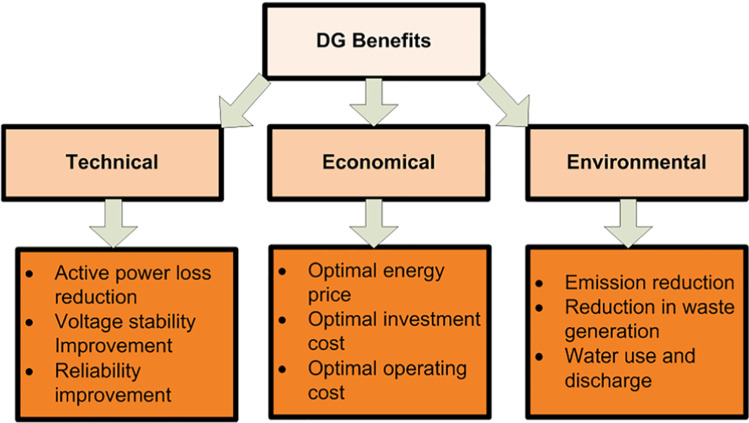
The inclusion of distributed generation (DG) into the electric power distribution system has risen quickly due to technological, economic, and environmental benefits [1–3] as seen in Fig. 1. Depending on the location and size of the DG, DG integration may have a beneficial or negative impact on the delivery system. The beneficial effects included into the distribution network are accomplished by positioning and sizing the DG optimally. The distribution network suffers as a result of DG’s erroneous position.
Fig. 1.
Advantages of DG benefits
Distribution companies (DISCOs) have not received the desired technological support as in transmission and generation, despite 30–40% of total investment in electric power sector is going to electric power distribution systems. In general, 3–6% of active power losses exist in electric power sector. The total distribution active power losses in developed countries are not greater than 10% of total active power losses in electric power sector. However, these active power losses are around 20% in developing countries like India. Due to this reason, electric power utilities in developing countries are trying to reduce active power losses by effective operating mechanisms like providing financial incentives. To manage active power losses in distribution network, an efficient and effective computation algorithm has to be developed for optimal placement of DG units so that active power losses in active distribution system are reduced. As per the statistics, energy sector is responsible for 70% of overall greenhouse gas emissions due to burning coal. Hence, more focus will be required in this sector. If the distribution companies are able to use low emission coefficient generators available as DG units in distribution network, then the amount of power purchased from thermal plants will be reduced. This leads to reduction of burning of coal and greenhouse gas emissions. Hence, there is a need to develop a robust computation algorithm for optimal utilization of DG units in active distribution system based on the reduction of greenhouse gas emissions. Due to these reasons, in this paper, DG placement and sizing are discussed based on active power loss and greenhouse gas emissions.
Many of the research findings have proposed various optimization methods and objective functions to identify the optimal position and scale of the DG units so that distribution businesses can benefit from adding the DG units into the distribution system. Optimal placement of DG units by considering the loss reduction as an objective using genetic algorithm for IEEE 14 and 30 bus distribution test systems is discussed in [4], for IEEE 33 and PG & E 69 bus distribution test systems is discussed in [5] and for IEEE 15 and PG & E 69 bus distribution test systems is discussed in [6]. Optimal placement of DG units in PG & E 69 bus distribution test systems by considering the loss reduction as an objective using particle swarm optimization is discussed in [7].
Optimal location and sizing of DG units in IEEE 33 and PG & E 69 bus test systems based on loss reduction using Quasi-Oppositional Chaotic Symbiotic Organisms Search (QOCSOS) algorithm are discussed in [8]. Optimal placement including sizing of DG units in IEEE 33 and 69 bus distribution test systems based on loss reduction using firefly algorithm is discussed in [9, 10] and using Hybrid Genetic Dragonfly Algorithm is discussed in [11] and using Crop Pollination Algorithm is discussed in [12]. Optimal location and size of DG units in IEEE 33 and 69 bus distribution test systems based on DISCO’s financial benefit using Self-Adaptive Levy Flight-Based Black Widow Optimizer are discussed in [13]. Optimal placement including sizing of DG units in IEEE 33 and 69 bus distribution test systems based on active power loss, reactive power loss, voltage deviation and line loading using Improved Raven Roosting Optimization is discussed in [14].
Optimal location and sizing of DG units in IEEE 33 and PG & E 69 bus test systems based on loss reduction and voltage deviation using enhanced genetic algorithm are discussed in [15], and using fuzzy logic controller, ant-lion optimization algorithm and particle swarm optimization are discussed in [16]. Optimal location and size of DG units in IEEE 33 and 69 bus distribution test systems based on voltage stability index using whale optimization are discussed in [17]. Identification of optimal location and size for DG units in IEEE 33 and PG & E 69 bus test systems based on loss reduction and voltage deviation using genetic algorithm is discussed in [18]. Optimal location and size identification for DG units in Tezpur University distribution system based on distribution loss reduction index and voltage deviation reduction index are discussed in [19]. Optimal placement of DG units in IEEE 33 bus test system based on emissions, voltage deviation and active power loss using spring search algorithm is discussed in [20]. Summary of all the discussed literature on DG placement is presented in Table 1.
Table 1.
Literature information
| Article | Test system | Objectives | Algorithm |
|---|---|---|---|
| [4] | IEEE 14, 30 | Loss reduction | Genetic algorithm |
| [5] | IEEE 33,PG & E 69 | Loss reduction | Genetic algorithm |
| [6] | IEEE 15,PG & E 69 | Loss reduction | Genetic algorithm |
| [7] | PG & E 69 | Loss reduction | Particle Swarm optimization |
| [8] | IEEE 33,PG & E 69 | Loss reduction | QOCSOS |
| [9] | IEEE 15,PG & E 69 | Loss reduction | Firefly algorithm |
| [11] | IEEE 15,PG & E 69 | Loss reduction | Hybrid genetic Dragonfly algorithm |
| [13] | IEEE 15,PG & E 69 | Disco’s benefit with loss reduction | Self-adaptive levy flight based black widow |
| [14] | IEEE 33, PG & E 69 | Active power loss | Improved raven roosting optimization |
| Reactive power loss | |||
| Voltage profile | |||
| Line loading | |||
| [15] | IEEE 33,PG & E 69 | Losses and voltage deviation | Enhanced genetic algorithm |
| [16] | IEEE 33 | Losses and voltage deviation | fuzzy logic controller |
| Ant–lion optimization algorithm | |||
| Particle swarm optimization | |||
| [17] | IEEE 33,PG & E 69 | Voltage stability index | whale optimization |
| [12] | IEEE 33,PG & E 69 | Loss reduction | Crop pollination algorithm |
| line loading | |||
| [10] | IEEE 33,PG & E 69 | Loss reduction | Firefly algorithm |
| [18] | IEEE 33,PG & E 69 | Loss reduction | Genetic algorithm |
| Voltage deviation | |||
| [19] | 6 Bus (Tezpur University) | DLRI,VDRI | Fuzzy’s expert system |
| [20] | IEEE 33 | Emissions | Spring search algorithm |
| Voltage deviation | |||
| Active power losses |
A novel improved Elitism oppositional Jaya algorithm is developed in [21] for optimal placement of DG units in IEEE 33 and 69 bus distribution test systems. Optimal placement of DG units in IEEE 33 and 69 bus distribution test systems by considering voltage limits at buses, current-carrying limits of lines, radial configuration, and no isolated node in the network as constraints is discussed in [22]. Optimal placement of renewable energy distributed generation units based on minimization of total active power loss and improvement of the voltage profile using coronavirus herd immunity optimizer is discussed in [23]. All of these study techniques contribute significantly to the optimal location of DG units, but none of them addressed the extra advantage of DISCO due to loss and emission reduction.
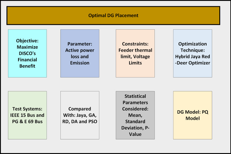
In this paper, a new hybrid meta-heuristic algorithm by combining jaya and red deer meta-heuristic algorithms is proposed to find the solution for DG placement optimization problem. DISCOs are getting some financial benefit due to integration of DG units. In this paper, financial benefit, i.e., DISCO’s financial benefit is derived based on loss and emission reduction. Maximization of this financial benefit is considered as an objective function subjected to constraints like thermal loading capacity of line and voltage deviation. This approach can be helpful to distribution network in environmental friendly with less carbon emissions and also with low active power losses. A brief schematic figure about the problem formulation is shown in Fig. 2.
Fig. 2.
Schematic diagram for the problem formulation
The main contributions of this paper are as follows:
Maximization of DISCO’s financial benefit due to loss and emission reduction is considered for the first time
First time a hybrid algorithm by combining Jaya and Red Deer meta-heuristic algorithms has been developed to exploit the advantages of both Jaya and Red Deer algorithms.
The performance of the proposed algorithm on the given objective function is validated statistically by implementing on IEEE 15 bus and PG& E 69 bus test systems
The rest of the paper is organized as follows: Sect. 2 describes the methodology, Sect. 3 presents results discussion and Sect. 4 provides conclusions of this paper
Methodology
This section discusses the Hybrid Jaya–Red Deer optimizer (HJRDO) and offers mathematical modeling of DISCO’s financial benefit due to loss and emissions reduction. It also presents an optimization issue relating to optimal placement of DG units.
DISCO’s financial benefit (DFB)
DISCO’s profit without DG units is defined as the difference between total revenue collected from customers and total money spent to purchase the power from the grid and emission penalty and it is shown in Eq. (1).
| 1 |
where EP is the emission penalty for a DISCO with out any DG units. EP is computed using Eq. (2).
| 2 |
In this paper, emission participation factor between generation companies and DISCO, i.e., is considered as 0.5, which means that emission penalty is shared between generation companies and DISCO equally.
DISCO’s profit with DG units is defined as the difference between total revenue collected from customers and total money spent on emission penalty and to purchase the power from the grid and DG owners and it is shown in Eq. (3).
| 3 |
Where is the emission penalty for a DISCO with DG units. is computed using Eq. (4).
| 4 |
DISCO’s Financial Benefit (DFB) is used as main parameter to place DG units. DFB is defined as the difference between DISCO’s profit with and without DG units and shown in Eq. (5)
| 5 |
Mathematical modeling of optimization problem
Mathematical modeling of DG placement problem consists maximization of DFB as objective function equation shown in Eq. (6) and also consists constraints like voltage deviation, thermal loading limit of lines, DG size and DG location as shown in equation (7).
| 6 |
subjected to
| 7 |
Hybrid Jaya–Red Deer optimizer
Jaya algorithm [24] is one of the most powerful meta-heuristic algorithm to reach near global optimum by moving the solution away from worst solution and moving toward best solution in a search space. Except for standard control factors like population size and iterations, this method does not require any extra control parameters. Jaya algorithm suffers with less local search or exploitation capability, and it may lead to converge solution at local optimum point instead of global [25].
Red Deer (RD) optimization algorithm [26] is developed based on mating process of Red Deers which are generally visible in Scotland. This optimization algorithm has good exploration and exploitation characteristics. Red Deers mating process is classified into 4 categories as shown below. The main advantage of RD optimization is better exploitation capability with Roaring of male RD phase, Fight between commander and stag phase and mating between stag and nearest hind phase.
Roaring of male RD (Local search, Exploitation)
Fight between commander and stag (Local search, Exploitation)
Mating between commander and hinds within hareem (Global search, Exploration)
Mating between commander and hinds from other hareem (Global search, Exploration)
Mating between stag and nearest hind (Exploration,Exploration)
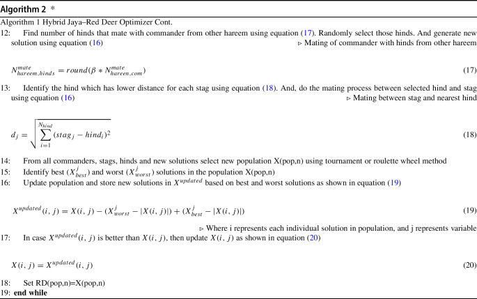
To achieve these objectives like good exploration and exploitation capabilities, this study proposes a unique hybrid algorithm based on Jaya and Red Deer that takes use of both Jaya and Red Deer algorithms. To overcome the problem of trapping the solution toward the local optimal point, the suggested Hybrid Jaya Red Deer Optimizer (HJRDO) obtains strong local and global searching capabilities. Algorithm 1 depicts the step-by-step method for HJRDO.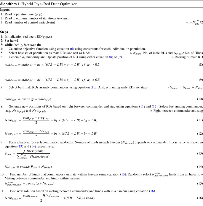
Analytical studies
The suggested approach was applied on IEEE 15 bus and PG & E 69 bus distribution systems to identify the best place and size for two DG units with 0.9 lagging power factor in the MATLAB. The information about maximum capacity of DG units and power factor, line and bus data of the test systems are drawn from [27]. Market clearing price to take the power from the grid is considered as 47 $/MWh; this is the realistic price taken from IEX website [28]. Fuel cost coefficient for DG units and emission coefficients data for DG units and substation bus are drawn from [29]. Backward and forward sweep load flow technique [30] is used in this paper to calculate the active power losses in the distribution system.
Case study: IEEE 15 bus radial distribution system
For determining the location and generating capacity of DG units of maximum 1MW capacity, the suggested HJRDO method is simulated ten times. For selecting the placement and generating capacity of DG unit, the best simulation in terms of greatest DISCO’s financial benefit is evaluated out of ten simulations. Table 2 shows the performance of the suggested method in a stochastic setting. As the suggested method gives the same amount of DISCO’s financial benefit above all simulations, the standard deviation is zero. A standard deviation of zero indicates that the suggested HJRDO gives a solution with no ambiguity.
Table 2.
Statistical performance of proposed HJRDO method
| Simulation | DFB ($/h) | Simulation | DFB($/h) |
|---|---|---|---|
| 1 | 34.01 | 6 | 34.01 |
| 2 | 34.01 | 7 | 34.01 |
| 3 | 34.01 | 8 | 34.01 |
| 4 | 34.01 | 9 | 34.01 |
| 5 | 34.01 | 10 | 34.01 |
| Min. | 34.01 | Max. | 34.01 |
| Mean | 34.01 | Std. | 0 |
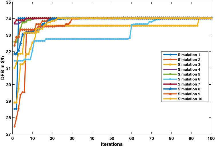
Figure 3 depicts the performance curves of the proposed HJRDO for optimal DG unit placement across ten simulations. Figure 3 shows that the suggested method is converging at DFB of 34.01 $/h for all ten runs.
Fig. 3.
Converging characteristics over 10 simulations—IEEE 15 bus test system
Table 3 shows the appropriate position and size for the two DG units in the IEEE 15 bus distribution scheme. According to Table 3, the distribution network will run at maximum DFB, i.e., 34.01 $/h, if two DG units with generating capacity of 1MW each are linked at bus 2 and 3.
Table 3.
Optimal location and size of DG units—PG & E 69 bus test system
| DG1 | DG2 | DFB | ||
|---|---|---|---|---|
| Location | Size (kW) | Location | Size (kW) | $/h |
| 2 | 1000 | 3 | 1000 | 34.01 |
The developed HJRDO for optimal placement of DG based on DFB is compared with existing meta-heuristic algorithms like GA [31], PSO [32], BWO [33], DA [34],Red Deer Optimization [35], Jaya [24] and presented in Table 4. From Table 4, it has been observed that the proposed HJRDO method provides maximum DFB of 34.01 $/h in comparison with Red Deer Optimization, GA and PSO. The performance of the proposed HJRDO for optimal DG placement has been statistically validated using the Wilcoxon rank sum test [36], and the resultant p values are shown in Table 4. The proposed HJRDO is more significant in comparison with GA, PSO, RD and BWO as the p values of these algorithms are less than 0.05. Whereas BWO, DA and Jaya algorithms provides same DFB value as proposed HJRDO, standard deviation of these algorithms is high that represents the proposed HJRDO method has no ambiguity toward reaching final solution in comparison with BWO, DA and Jaya algorithms. The individual values of power loss and emission values at DISCO’s financial benefit of 34.01 $/h are presented in Table 5.
Table 4.
Validation of proposed HJRDO method in stochastic environment—IEEE 15 bus test system
| Simulation | RD-Jaya | RD [35] | pso [32] | GA [31] | BWO [33] | Jaya [24] | DA [34] |
|---|---|---|---|---|---|---|---|
| 1 | 34.01 | 32.92 | 33.33 | 33.96 | 33.91 | 34.01 | 32.77 |
| 2 | 34.01 | 26.95 | 31.84 | 33.99 | 33.94 | 34.01 | 32.77 |
| 3 | 34.01 | 26.23 | 30.66 | 32.99 | 33.97 | 34.01 | 34.01 |
| 4 | 34.01 | 29.7 | 29.62 | 31.75 | 33.99 | 34.01 | 34.01 |
| 5 | 34.01 | 28.59 | 28.21 | 31.55 | 33.96 | 34.01 | 34.01 |
| 6 | 34.01 | 29.09 | 30.63 | 32.98 | 33.97 | 33.56 | 34.01 |
| 7 | 34.01 | 30.74 | 31.17 | 30.66 | 33.95 | 33.99 | 34.01 |
| 8 | 34.01 | 28.8 | 25.74 | 33.80 | 33.98 | 34.01 | 34.01 |
| 9 | 34.01 | 27.61 | 30.91 | 33.26 | 34.00 | 34.00 | 34.01 |
| 10 | 34.01 | 28.35 | 30.2 | 30.65 | 33.95 | 33.57 | 34.01 |
| Min | 34.01 | 26.23 | 25.74 | 30.65 | 33.91 | 33.56 | 32.77 |
| Max | 34.01 | 32.92 | 33.33 | 33.99 | 34.00 | 34.01 | 34.01 |
| Mean | 34.01 | 28.898 | 30.231 | 32.559 | 33.962 | 33.918 | 33.762 |
| Std | 0 | 1.9214 | 2.0685 | 1.3050 | 0.0262 | 0.1862 | 0.5228 |
| p value | NA | 0.0000 | 0.0000 | 0.0025 | 0.0000 | 0.1355 | 0.1510 |
Table 5.
Optimal power loss (in MW) and emission (in kg) on IEEE 15 bus test system
| CO | SO | NO | CO | Total emissions | Power loss |
|---|---|---|---|---|---|
| 1172 | 1.3 | 2.1 | 2.8 | 1178.2 | 0.019 |
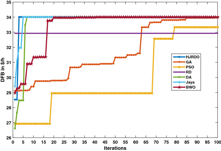
Figure 4 depicts a comparison of the proposed HJRDO with existing meta-heuristic algorithms in terms of convergence characteristics. The suggested HJRDO exhibits quick convergence properties. HJRDO achieves the ideal point, i.e., maximal DAB, faster than other meta-heuristic algorithms. The DA and Jaya algorithms are reaching the maximum DFB value, i.e., 34.01 $/h same as proposed HJRDO but with more uncertainty in reaching near to global optimum, whereas other meta-heuristic algorithms like GA, PSO, RD and BWO fall behind HJRDO.
Fig. 4.
Validation in terms of converging characteristics—IEEE 15 bus test system
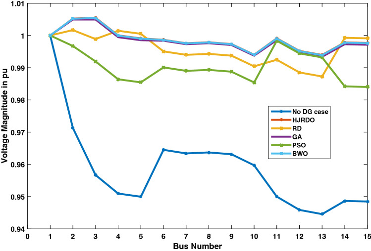
Figure 5 depicts the voltage at each bus in the IEEE 15 bus distribution network. Voltage at each bus is lower in the absence of DG units in the system than in the presence of DG units owing to reverse power flow, which reduces losses and improves voltage profile. Voltage profiles with HJRDO are better than GA, PSO, RD and BWO, and almost near to one per unit.
Fig. 5.
Validation in terms of voltage profile—IEEE 15 bus test system
Average voltage deviation from flat voltage profile is considered as a single statistical numerical value to validate the proposed algorithm by comparing with other meta-heuristic techniques and presented in Table 6. From Table 6, it is observed that HJRDO, Jaya and DA have same mean voltage deviation from flat voltage and better then remaining meta-heuristic algorithms. Even though HJRDO has same mean voltage deviation as Jaya and DA, HJRDO has less ambiguity to reach global optimum with less standard deviation value.
Table 6.
Validation of proposed HJRDO method in terms of average voltage deviation in IEEE 15 bus test system
Case study: PG& E 69 bus radial distribution system
The proposed HJRDO technique is simulated 10 times to determine the placement and generating capacity of two DG units with a maximum capacity of 1MW in PG& E 69 bus radial distribution system. Out of 10 simulations, the best simulation in terms of highest DFB is assessed for determining the placement and producing capacity of DG unit. The performance of the proposed approach in a stochastic situation is shown in Table 7.
Table 7.
Statistical performance of proposed HJRDO method-PG& E 69 bus radial distribution system
| Simulation | DFB ($/h) | Simulation | DFB ($/h) |
|---|---|---|---|
| 1 | 41.52 | 6 | 41.521 |
| 2 | 41.52 | 7 | 40.97 |
| 3 | 40.98 | 8 | 41.52 |
| 4 | 41.52 | 9 | 41.52 |
| 5 | 41.52 | 10 | 41.46 |
| Min. | 40.97 | Max. | 41.52 |
| Mean | 41.41 | Std. | 0.227 |
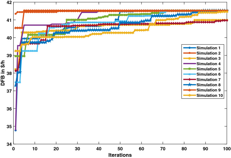
Figure 6 depicts the performance curves of the proposed HJRDO for optimal DG unit placement across ten simulations. Figure 6 shows that the suggested method is converging at DFB of 41.52 $/h for all seven runs out of 10 simulations, for the remaining three simulations also solution not far from maximum DFB value.
Fig. 6.
Converging characteristics over 10 simulation Moderns—PG& E 69 bus test system
Table 8 shows the appropriate position and size for the two DG units in the PG & E 69 bus distribution scheme. According to Table 8, the distribution network will run at maximum DFB, i.e., 41.52 $/h, if two DG units with generating capacity of 1MW each are linked at bus 61.
Table 8.
Optimal location and size of DG units—PG & E 69 bus test system
| DG1 | DG2 | DFB | ||
|---|---|---|---|---|
| Location | Size (kW) | Location | Size (kW) | $/h |
| 61 | 1000 | 61 | 1000 | 41.52 |
The performance of developed HJRDO for optimal placement of DG in PG & E 69 bus test system based on DFB is compared with existing meta-heuristic algorithms like GA [31], PSO [32], BWO [33], DA [34], Red Deer Optimization [35], Jaya [24] and presented in Table 9. From Table 9, it has been observed that the proposed HJRDO method provides maximum DFB of 41.52 $/h in comparison with Red Deer Optimization, GA and PSO. The performance of the proposed HJRDO for optimal DG placement has been statistically validated using the Wilcoxon rank sum test [36], and the resultant p values are shown in Table 9. The proposed HJRDO is more significant in comparison with GA, PSO, RD, Jaya and DA as the p values of these algorithms are less than 0.05. Whereas BWO, DA and Jaya algorithms provide same DFB value as proposed HJRDO, standard deviation of these algorithms is high which represents that the proposed HJRDO method has less ambiguity toward reaching final solution in comparison with BWO, DA and Jaya algorithms.
Table 9.
Validation of proposed HJRDO method in stochastic environment—PG & E 69 bus test system
| Simulation | RD-Jaya | RD [35] | DA [34] | GA [31] | pso [32] | Jaya [24] | BWO [33] |
|---|---|---|---|---|---|---|---|
| 1 | 41.52 | 41.44 | 40.74 | 31.87 | 40.37 | 41.41 | 41.44 |
| 2 | 41.52 | 41.26 | 41.42 | 32.03 | 34.64 | 41.52 | 41.45 |
| 3 | 40.98 | 40.88 | 40.74 | 40.6 | 39.84 | 41.52 | 41.46 |
| 4 | 41.52 | 40.06 | 41.52 | 33.64 | 39.74 | 41.52 | 41.49 |
| 5 | 41.52 | 41.03 | 41.52 | 38.29 | 40.54 | 41.52 | 41.45 |
| 6 | 41.52 | 39.54 | 41.52 | 38.85 | 40.84 | 40.68 | 40.31 |
| 7 | 40.97 | 40.54 | 41.52 | 34.69 | 39.15 | 41.52 | 41.45 |
| 8 | 41.52 | 39.87 | 41.52 | 33.33 | 40.47 | 41.52 | 41.49 |
| 9 | 41.52 | 39.11 | 41.52 | 32.23 | 40.84 | 39.37 | 41.41 |
| 10 | 41.46 | 40.84 | 41.52 | 32.72 | 29.06 | 40.74 | 41.51 |
| Min | 40.97 | 39.11 | 40.74 | 31.87 | 29.06 | 39.37 | 40.31 |
| Max | 41.52 | 41.44 | 41.52 | 40.60 | 40.84 | 41.52 | 41.51 |
| Mean | 41.41 | 40.46 | 41.35 | 34.83 | 38.55 | 41.13 | 41.35 |
| Std | 0.227413 | 0.776703 | 0.325105 | 3.213237378 | 3.804025 | 0.702627 | 0.365154 |
| p value | NA | 0.001869 | 0.002773 | 5.77653E−05 | 0.014905 | 0.03099 | 0.20382 |
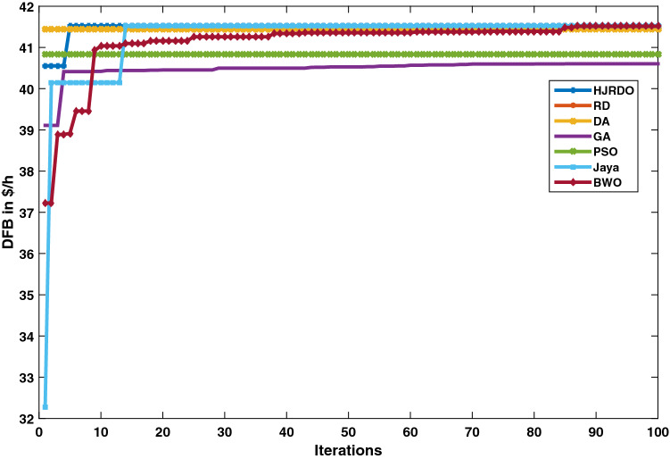
Figure 7 depicts a comparison of the proposed HJRDO with existing meta-heuristic algorithms in terms of convergence characteristics while finding the optimal location and size of DG units for PG & E 69 bus test system. The suggested HJRDO exhibits quick convergence properties. HJRDO achieves the ideal point, i.e., maximal DFB, faster than other meta-heuristic algorithms. The DA, BWO and Jaya algorithms are reaching the maximum DFB value, i.e., 41.52 $/h same as proposed HJRDO but with more uncertainty in reaching near to global optimum, whereas other meta-heuristic algorithms like GA, PSO and RD fall behind HJRDO.
Fig. 7.
Validation in terms of converging characteristics—PG & E 69 bus test system
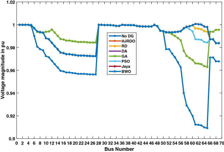
Figure 8 depicts the voltage at each bus in the PG & E 69 bus distribution network. Voltage at each bus is lower in the absence of DG units in the system than in the presence of DG units owing to reverse power flow, which reduces losses and improves voltage profile. Overall voltage profiles on PG & E 69 bus distribution network with HJRDO are better than GA, PSO and RD, and almost near to one per unit. Table 10 presents the optimal location and size of each DG units in both test systems with respect to each meta-heuristic algorithm. The proposed HJRDO, Jaya and DA algorithms suggest same optimal location and size for each DG unit with same value of DISCO’s financial benefit, i.e., 34.01 $/h in case of IEEE 15 bus test system and 41.52 $/h in case of PG & E 69 bus test system.
Fig. 8.
Validation in terms of voltage profile—PG & E 69 bus test system
Table 10.
Optimal location and optimal size information of tested systems for different compared algorithms
| Algorithm | IEEE 15 bus | PG & E 69 bus | ||||||
|---|---|---|---|---|---|---|---|---|
| DG1 | DG2 | DG1 | DG2 | |||||
| Location | Size (KW) | Location | Size (KW) | Location | Size (KW) | Location | Size (KW) | |
| HJRDO | 2 | 1000 | 3 | 1000 | 61 | 1000 | 61 | 1000 |
| Red Deer [35] | 4 | 785 | 2 | 994 | 62 | 793 | 60 | 992 |
| DA [34] | 3 | 1000 | 2 | 1000 | 61 | 1000 | 61 | 1000 |
| GA [31] | 2 | 1000 | 4 | 999 | 12 | 965 | 61 | 1000 |
| PSO [32] | 3 | 1000 | 3 | 1000 | 60 | 1000 | 58 | 1000 |
| Jaya [24] | 2 | 1000 | 3 | 1000 | 61 | 1000 | 61 | 1000 |
| BWO [33] | 3 | 998 | 2 | 999 | 61 | 999 | 61 | 999 |
Conclusions
The Hybrid Jaya Red Deer Optimization (HJRDO) method was designed to discover the best location and size of DG units by combining the benefits of both jaya and red deer meta-heuristic techniques. The optimization problem that deals with optimal placement of DG units has an objective function, which is maximization of DISCO’s financial benefit based on active power losses and green house gas emissions, and it also takes bus voltage limits and thermal limits of the line into account as constraints.
Robustness of swarm intelligence-based algorithms is measured in terms of deviation from its global optimum point. If deviation is less, i.e., standard deviation is less, then the algorithm will be robust for the working problem. The performance of the proposed hybrid algorithm on the optimal DG placement problems was validated in a stochastic environment by considering two test systems, i.e., IEEE 15 bus and PG & E 69 bus test systems. For IEEE 15 bus system, the standard deviation is zero, but in case of PG & E 69 bus system, it is 0.227. But in both cases, deviation is less in comparison with other swarm intelligence based algorithms. From these results, authors concluded that the proposed algorithm has robust performance by reaching global point always in case of small test system whereas it slightly deviated from global in case of larger test systems like PG & E 69 bus.
Simulation results of this study show that HJRDO method provides maximum DFB for distribution companies while placing the DG units at suitable location and size with less ambiguity to reach near global optimum solution in comparison with a well known existing meta-heuristic algorithms. The proposed approach provides maximum DFB for distribution companies, i.e., 34.01 $/MWh by keeping two DG units with size 1MW at bus 2 and bus 3 in case of IEEE 15 bus and 41.52 $/MWh by keeping two DG units with size 1 MW at bus 61 in case of PG & E 69 bus test system.
This work may be beneficial to DISCO operators in other regions of the world where there are a large number of DG units accessible to integrate with the distribution network. This work may be beneficial to distribution network operators in order to incorporate DG units into the network with the greatest financial advantage. This DG placement problem may further be expanded by including emissions and dependability as goals, as well as the influence of load modeling.
List of symbols
Customer energy price in $/MWh
Market price in $/MWh
Emission penalty sharing factor
Cost coefficients of ith DG units
CO from ith DG unit in Kg/MW
CO emission based on power drawn from substation bus in Kg/MW
emission from ith DG unit in Kg/MW
emission based on power drawn from substation bus in Kg/MW
- DFB
DISCO’s financial benefit in $/h
DISCO’s profit in $/h
DISCO’s profit in presence of DG units in $/h
Base case emission penalty in $/h
Emission penalty in presence of DG units in $/h
Current through line ’l’
Thermal limit for line ’l’
- n
Number of buses in test system
Number of DG units
emission from ith DG unit in Kg/MW
emission based on power drawn from substation bus in Kg/MW
Generation capacity of ’ith’ DG unit
Generation of ith DG unit in MW
Power demand in MW
Base case active power loss in MW
Active power losses in presence of DG units in MW
Penalty for emission in $/Kg
Penalty for CO emission in $/Kg
Penalty for SO emission in $/Kg
- Pe
Penalty for NO emission in $/Kg
- SO
SO emission from ith DG unit in Kg/MW
- SO
SO emission based on power drawn from substation bus in Kg/MW
ith bus voltage
Lower limit for ith bus voltage
Upper limit for ith bus voltage
Author Contributions
GVNL and AJL contributed to conceptualization; GVNL and AJL contributed to methodology; GVNL contributed to software; GVNL and AJL contributed to validation; GVNL and AJL contributed to formal analysis; GVNL contributed to investigation; GVNL contributed to resources; GVNL contributed to data curation; GVNL and VV contributed to writing—original draft preparation; AJL and VV contributed to writing—review and editing; GVNL contributed to visualization; AJL contributed to supervision; AJL contributed to project administration. All authors have read and agreed to the published version of the manuscript.
Funding
No funding received
Data Availability
No dataset used for this work.
Declarations
Conflict of interest
The authors declare no conflict of interest.
Ethical approval
Not applicable.
Footnotes
Publisher's Note
Springer Nature remains neutral with regard to jurisdictional claims in published maps and institutional affiliations.
Contributor Information
G. V. Naga Lakshmi, Email: nagalakshmi.g@uceou.edu.
A. Jayalaxmi, Email: ajl1994@jntuh.ac.in
Venkataramana Veeramsetty, Email: dr.vvr.research@gmail.com.
References
- 1.Veeramsetty V, Chintham V, DM VK. Lmp computation at dg buses in radial distribution system. Int J Energy Sect Manag. 2018;12(3):364. doi: 10.1108/IJESM-03-2017-0002. [DOI] [Google Scholar]
- 2.Veeramsetty V, Chintham V, Kumar DMV. Probabilistic locational marginal price computation in radial distribution system based on active power loss reduction. IET Gener Transm Distrib. 2020;14(12):2292. doi: 10.1049/iet-gtd.2019.0952. [DOI] [Google Scholar]
- 3.Veeramsetty V, Chintham V, Vinod Kumar D. Proportional nucleolus game theory-based locational marginal price computation for loss and emission reduction in a radial distribution system. Int Trans Electr Energy Syst. 2018;28(8):e2573. doi: 10.1002/etep.2573. [DOI] [Google Scholar]
- 4.Kim J, Nam S, Park S, Singh C. Dispersed generation planning using improved hereford ranch algorithm. Electr Power Syst Res. 1998;47(1):47. doi: 10.1016/S0378-7796(98)00038-8. [DOI] [Google Scholar]
- 5.Gandomkar M, Vakilian M, Ehsan M. A genetic-based tabu search algorithm for optimal dg allocation in distribution networks. Electr Power Compon Syst. 2005;33(12):1351. doi: 10.1080/15325000590964254. [DOI] [Google Scholar]
- 6.Veeramsetty V, Lakshmi GN, Jayalaxmi A (2012) In: 2012 International conference on computing, electronics and electrical technologies (ICCEET) (IEEE). pp. 86–91
- 7.Prommee W, Ongsakul W. Optimal multiple distributed generation placement in microgrid system by improved reinitialized social structures particle swarm optimization. Eur Trans Electr Power. 2011;21(1):489. doi: 10.1002/etep.456. [DOI] [Google Scholar]
- 8.Truong KH, Nallagownden P, Elamvazuthi I, Vo DN. An improved meta-heuristic method to maximize the penetration of distributed generation in radial distribution networks. Neural Comput Appl. 2020;32(14):10159. doi: 10.1007/s00521-019-04548-4. [DOI] [Google Scholar]
- 9.Lakshmi GN, Jayalaxmi A, Veeramsetty V (2020) In: IOP conference series: materials science and engineering, vol. 981 (IOP Publishing,). 981: 042060
- 10.Jalili A, Taheri B. Optimal sizing and sitting of distributed generations in power distribution networks using firefly algorithm. Technol Econ Smart Grids Sustain Energy. 2020;5(1):1. doi: 10.1007/s40866-020-00081-9. [DOI] [Google Scholar]
- 11.Lakshmi GN, Jayalaxmi A, Veeramsetty V. Optimal placement of distribution generation in radial distribution system using hybrid genetic dragonfly algorithm. Technol Econ Smart Grids Sustain Energy. 2021;6(1):1. doi: 10.1007/s40866-021-00107-w. [DOI] [Google Scholar]
- 12.Jayasree M, Sreejaya P, Bindu G. Multi-objective metaheuristic algorithm for optimal distributed generator placement and profit analysis. Technol Econ Smart Grids Sustain Energy. 2019;4(1):1. doi: 10.1007/s40866-019-0067-z. [DOI] [Google Scholar]
- 13.Venkata NLG, Askani JL, Veeramsetty V. Optimal placement of distributed generation based on disco’s additional benefit using self adaptive levy flight based black widow optimization. Int J Emerg Electr Power Syst. 2021;22(4):401. doi: 10.1515/ijeeps-2020-0280. [DOI] [Google Scholar]
- 14.Nagaballi S, Kale VS. Pareto optimality and game theory approach for optimal deployment of dg in radial distribution system to improve techno-economic benefits. Appl Soft Comput. 2020;92:106234. doi: 10.1016/j.asoc.2020.106234. [DOI] [Google Scholar]
- 15.Almabsout EA, El-Sehiemy RA, An ONU, Bayat O. A hybrid local search-genetic algorithm for simultaneous placement of dg units and shunt capacitors in radial distribution systems. IEEE Access. 2020;8:54465. doi: 10.1109/ACCESS.2020.2981406. [DOI] [Google Scholar]
- 16.Samala RK, Kotapuri MR. Optimal allocation of distributed generations using hybrid technique with fuzzy logic controller radial distribution system. SN Appl Sci. 2020;2(2):1. doi: 10.1007/s42452-020-1957-3. [DOI] [Google Scholar]
- 17.Selim A, Kamel S, Nasrat LS, Jurado F. Voltage stability assessment of radial distribution systems including optimal allocation of distributed generators. Int J Interact Multimedia Artif Intell. 2020 doi: 10.9781/ijimai.2020.02.004. [DOI] [Google Scholar]
- 18.Aravinth A, Vatul VA, Narayanan K, Muthukumar K, Senjyu T. A multi-objective framework to improve voltage stability in a distribution network. Int J Emerg Electr Power Syst. 2019 doi: 10.1515/ijeeps-2018-0239. [DOI] [Google Scholar]
- 19.Manas M, Saikia BJ, Baruah DC. Optimal distributed generator sizing and placement by analytical method and fuzzy expert system: a case study in tezpur university, india. Technol Econ Smart Grids Sustain Energy. 2018;3(1):1. doi: 10.1007/s40866-018-0038-9. [DOI] [Google Scholar]
- 20.Dehghani M, Montazeri Z, Malik O. Optimal sizing and placement of capacitor banks and distributed generation in distribution systems using spring search algorithm. Int J Emerg Electr Power Syst. 2020 doi: 10.1515/ijeeps-2019-0217. [DOI] [Google Scholar]
- 21.Pemmada S, Patne NR, Kumar A, Manchalwar AD. Optimal planning of power distribution network by a novel modified jaya algorithm in multiobjective perspective. IEEE Syst J. 2021;16:4411. doi: 10.1109/JSYST.2021.3132300. [DOI] [Google Scholar]
- 22.Pemmada S, Patne NR, Manchalwar AD, Ajay TK (2021) In: 2021 9th IEEE international conference on power systems (ICPS). pp. 1–6. 10.1109/ICPS52420.2021.9670411
- 23.Kumar D, Pemmada S, Patne, NR (2022) In: 2022 International conference on intelligent controller and computing for smart power (ICICCSP). pp. 1–6. 10.1109/ICICCSP53532.2022.9862484
- 24.Rao R. Jaya: a simple and new optimization algorithm for solving constrained and unconstrained optimization problems. Int J Ind Eng Comput. 2016;7(1):19. [Google Scholar]
- 25.Zitar RA, Al-Betar MA, Awadallah MA, Doush IA, Assaleh K. An intensive and comprehensive overview of jaya algorithm, its versions and applications. Arch Comput Methods Eng. 2021;29:763. doi: 10.1007/s11831-021-09585-8. [DOI] [PMC free article] [PubMed] [Google Scholar]
- 26.Fathollahi-Fard AM, Hajiaghaei-Keshteli M, Tavakkoli-Moghaddam R. Red deer algorithm (rda): a new nature-inspired meta-heuristic. Soft Comput. 2020;24(19):14637. doi: 10.1007/s00500-020-04812-z. [DOI] [Google Scholar]
- 27.Veeramsetty V, Venkaiah C, Kumar DV. Hybrid genetic dragonfly algorithm based optimal power flow for computing lmp at dg buses for reliability improvement. Energy Syst. 2018;9(3):709. doi: 10.1007/s12667-017-0268-2. [DOI] [Google Scholar]
- 28.Iex-market data (2020). https://www.iexindia.com/. Accessed on 11 Feb 2020
- 29.Veeramsetty V. Shapley value cooperative game theory-based locational marginal price computation for loss and emission reduction. Protect Control Mod Power Syst. 2021;6(1):1. [Google Scholar]
- 30.Sunisith S, Meena K. Backward/forward sweep based distribution load flow method. Int Electr Eng J. 2014;5(9):1539. [Google Scholar]
- 31.Goldberg DE, Holland JH (1988) Genetic algorithms and machine learning
- 32.Eberhart R, Kennedy J (1995) In: MHS’95. Proceedings of the sixth international symposium on micro machine and human science (Ieee). pp. 39–43
- 33.Hayyolalam V, Kazem AAP. Black widow optimization algorithm: a novel meta-heuristic approach for solving engineering optimization problems. Eng Appl Artif Intell. 2020;87:103249. doi: 10.1016/j.engappai.2019.103249. [DOI] [Google Scholar]
- 34.Mirjalili S. Dragonfly algorithm: a new meta-heuristic optimization technique for solving single-objective, discrete, and multi-objective problems. Neural Comput Appl. 2016;27(4):1053. doi: 10.1007/s00521-015-1920-1. [DOI] [Google Scholar]
- 35.Fathollahi-Fard AM, Hajiaghaei-Keshteli M, Tavakkoli-Moghaddam R. Red deer algorithm (rda): a new nature-inspired meta-heuristic. Soft Comput. 2020;24(19):14637. doi: 10.1007/s00500-020-04812-z. [DOI] [Google Scholar]
- 36.Ryan TP. Statistical methods for quality improvement. Hoboken: Wiley; 2011. [Google Scholar]
Associated Data
This section collects any data citations, data availability statements, or supplementary materials included in this article.
Data Availability Statement
No dataset used for this work.


