

Abstract
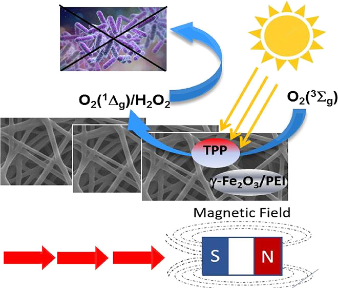
We have prepared photoactive multifunctional nanofiber membranes via the simple electrospinning method. The antibacterial and photocatalytic properties of these materials are based on the generation of singlet oxygen formed by processes photosensitized by the tetraphenylporphyrin encapsulated in the nanofibers. The addition of magnetic features in the form of magnetic maghemite (γ-Fe2O3) nanoparticles stabilized by polyethylenimine enables additional functionalities, namely, the postirradiation formation of hydrogen peroxide and improved photothermal properties. This hybrid material allows for remote manipulation by a magnetic field, even in hazardous and/or highly microbial contaminant environments.
Introduction
Due to the increasing resistance of bacteria to antibiotics,1 innovative strategies and novel antibacterial agents have been developed to prevent and/or treat infections caused by multidrug-resistant organisms.2 Antibacterial photodynamic inactivation (PDI) is a promising alternative to antibiotic therapy because bacteria do not readily develop resistance to PDI.3,4 PDI utilizes light in combination with a photosensitizer (drug) to kill the bacteria. The general mechanism starts with the absorption of light by a photosensitizer followed by the formation of reactive singlet oxygen O2(1Δg) with antibacterial properties.
For more than a decade, electrospun polymeric nanofibers have been used as solid supports for O2(1Δg) photosensitizers.5 In contrast to bulk polymer films, nanofibers exhibit large surface area to volume ratios, flexibility in surface functionality, and superior mechanical properties (e.g., stiffness and tensile strength) and can be used for a broad range of applications, such as filtration,6,7 wound dressings,8 scaffolds for tissue engineering,9,10 and sensing.11 Different types of antibacterial polymeric nanofiber membranes with encapsulated or externally bound photosensitizers suitable for biological applications12 have been prepared, including water disinfection,13,14 pollutants,15,16 warfare agents,17 photodegradation, or the fabrication of dressing materials to treat chronic wounds.8 The singlet oxygen photogenerated inside nanofibers with a lifetime (τΔ) of a few tens of microseconds18 diffuses outside to the environment and to biological targets (bacteria) to be oxidized. In contrast, the value in aqueous environments and cells decreases below 4 μs,19,20 with a diffusion length of several tens of nanometers during a period of τΔ.21 Due to the low diffusion length of singlet oxygen, antibacterial applications require nanofibers with a hydrophilic surface for the effective adsorption of bacteria.22 Recently, we also prepared multifunctional antibacterial materials tailored for other applications capable of performing multiple tasks, e.g., photodisinfection, decontamination, separation, or enzyme catalysis, using the same material.23,24
Magnetic materials have recently undergone intensive research because of their suitable properties for a diverse set of potential applications in biomedicine and catalysis.25−28 At the nanoscale, magnetic materials display novel physical effects that distinguish them from their bulk counterpart.29
In this work, we prepared nanofiber membranes with magnetic nanoparticles and measured their physicochemical properties and ability to kill bacteria.
This type of magnetic nanofiber membrane should have the advantage of easy-to-use magnetic manipulation/separation, even in hazardous and/or highly microbially contaminated environments.30
Experimental Section
Chemicals
Iron(II) chloride tetrahydrate, iron(III) chloride hexahydrate, polyethylenimine (PEI, Mw ∼ 25,000), 24 wt % ammonia solution, 5,10,15,20-tetraphenylporphyrin (TPP), N,N′-dimethylformamide (DMF), uric acid sodium salt, tetraethylammonium bromide (TEAB), ampicillin, potassium iodide, and other inorganic salts were all obtained from Sigma-Aldrich and used as delivered. Phosphate-buffered saline (PBS), agar, and LB medium (Lennox) were all obtained from Carl Roth GmbH and used as delivered. Tetrahydrofuran (THF, Sigma-Aldrich) was dried with a PureSolv MD5 solvent purification system (Innovative Technology). Tecophilic HP-60D-60 (TECO) was purchased from Lubrizol (USA).
Preparation of Magnetic Nanoparticles and Nanofiber Material
Magnetic nanoparticles were prepared using the modified chemical coprecipitation method.31 Briefly, 0.99 g of iron(II) chloride tetrahydrate and 2.7 g of iron(III) chloride hexahydrate (1:2 M ratio) were dissolved in 100 mL of deoxygenated distilled water. The solution was heated to 80 °C with vigorous stirring, and 10 mL of NH4OH (24 wt %) was then added. The mixture was continuously stirred at 80 °C for 30 min, during which time the color changed gradually to black. The resulting nanoparticles were separated using a permanent magnet and washed five times with 100 mL of deoxygenated distilled water. The washed nanoparticles were resuspended in 100 mL of deoxygenated distilled water to obtain the final stock solution.
To the nanoparticles magnetically separated from 20 mL of the above stock solution, 20 mL of 200 mg/L PEI solution was added to stabilize them. The nanoparticles in the mixture were agitated using an Elmasonic S40H 340 W sonicator (Elma, Germany) for 20 min. The mixture was then incubated at room temperature on an orbital shaker at 150 RPM for 30 min. The resulting nanoparticles stabilized by PEI (MNPs) were separated using a permanent magnet and washed five times with 25 mL of deoxygenated distilled water. The washed MNPs were resuspended in 20 mL of deoxygenated distilled water to obtain the final stock solution.
The nanofiber membranes were produced using a needle electrospinning apparatus (Figure S1 in the Supporting Information). A mixture of 1 wt % TPP, 0.12 wt % TEAB, and 98.85 wt % TECO was dissolved in a 7:3 THF:DMF mixture to prepare a 6 wt % solution used for the electrospinning process. Ten milligrams of dried MNPs was resuspended in 5 mL of TECO electrospinning solution and agitated using an Elmasonic S40H 340 W sonicator (Elma, Germany) for 5 min. The solution was loaded in a 20 mL syringe capped with a 21 G blunted stainless steel needle connected to the positive terminal of the high-voltage power supply (20 kV). At a distance of 11 cm from the needle tip, a grounded collector wrapped in aluminum foil was placed to collect nanofibers. Standard electrospinning was carried out for 1 h at a rate of 1 mL/h.
Characterization of Materials
Nanofiber and nanoparticle morphologies were studied with a scanning electron Nova NanoSEM 230 microscope (FEI, Czech Republic) and a transmission electron JEOL JEM-1011 microscope (JEOL, USA) equipped with a CCD camera with acquisition software (Olympus, Germany). The nanofiber diameters were measured using the NIS Elements 4.0 image analysis software (Laboratory Imaging, Czech Republic). The nanoparticle size, size distributions, and zeta potential in water were determined by dynamic light scattering on a Zetasizer Nano ZS particle size analyzer from Malvern (United Kingdom) after 10 min of 340 W sonication with an Elmasonic S40H (Elma, Germany). The hydrophobic/hydrophilic nature of the membranes was characterized by performing apparent contact angle measurements using a surface energy evaluation system (See System, Czech Republic). Temperature changes of the membranes were characterized by GTC 400 C infra-red camera (Bosch, Germany).
Mössbauer spectroscopy of 57Fe was performed on a Wissel spectrometer using a transmission arrangement and scintillating detector ND-220-M (NaI:Tl+). α-Fe foil was used as a standard, and the fitting procedure was performed using the NORMOS program.
DC magnetization was measured on a 42.1 mg magnetic nanofiber membrane (corresponding to 1.3 mg MNPs) using an MPMS 7 T SQUID magnetometer under a helium atmosphere (5 mbar) at 298 and 310 K in a magnetic field from −2 to 2 T.
Spectral and Photophysical Properties
UV-vis absorption spectra were recorded using Unicam 340 and Varian 4000 spectrometers. The steady-state fluorescence spectra were monitored using an FLS 980 (Edinburgh Instruments, UK) spectrofluorimeter. For time-resolved measurements, nanofiber membranes fixed on quartz plates were irradiated by a Lambda Physik LPX 205 excimer laser (λexc = 308 nm, pulse length ∼ 28 ns). Time-resolved near-infrared luminescence at approximately 1270 nm was observed using optical filters and a homemade detector unit (Ge diode Judson J16-8SP-R05M-HS with amplifier) and averaged to increase the signal-to-noise ratio. The luminescence of O2(1Δg) was calculated as the difference between luminescence in the air atmosphere and vacuum. This procedure was described in detail in our previous paper.21
Detection of Hydrogen Peroxide
Nanofiber membranes on quartz plates (0.1 × 1 × 4 cm) were immersed in 0.77 M sodium borate buffer (3 mL) and irradiated by visible light for 75 min using a stabilized xenon lamp (400 W, Solar simulator, Newport).
For the scopoletin (SPT) fluorescence assay, 8 μM SPT in the presence or absence of 88 nM horseradish peroxidase (HRP) in 0.77 M sodium borate buffer (pH 8.2) was mixed with the buffer solution (1:1) after the removal of the nanofiber material treated with a solar simulator. Fluorescence quenching of scopoletin by hydrogen peroxide catalyzed by HRP was detected at 462 nm (λex = 350 nm).
Leaching Behavior
The leaching of the TPP photosensitizer from the membrane in different environments was tested using UV-vis and fluorescence spectroscopy. Typically, the UV-vis and/or fluorescence spectra of the extract were recorded after 72 h of immersion of the membranes (18 cm2) into 3 mL of the water, PBS, saline, or sweat mimic medium incubated at 37 °C.
For the detection of iron leakage from magnetic membranes, a QuantofixTM assay for iron was used with a detection range of 2–100 mg/L. After shaking the magnetic membrane (10 cm2) in 2.5 mL H2O for 12 days, traces of iron were detected in the extract.
Photooxidation Properties
A piece of the nanofiber material (2 cm2) fixed on quartz glass was placed in a thermostatted 10 mm quartz cell (22 °C) that contained 0.12 M iodide detection solution or 10–4 M uric acid in 0.02 M phosphate buffer (pH = 7.0). The cell was irradiated with an 18 W LED source (λem = 414 nm). The UV-vis absorbance changes at 287 or 351 nm (attributed to the formation of I3– in the iodide test) or 292 nm (attributed to photodegradation of uric acid) were recorded at regular intervals and compared to those of a blank solution of the same composition that was stored in the dark. The spectra and total irradiance of the used light sources were evaluated with an ILT960 spectroradiometer SpectriLight (International Light Technologies, USA). Details were described in our previous paper.32
Antibacterial Assays
A culture of Escherichia coli DH5α (Invitrogen, California, USA) with the plasmid pGEM11Z (Promega, Wisconsin, USA) was incubated at 37 °C while stirring in LB medium after the addition of ampicillin. Incubation was terminated when the absorbance at 560 nm reached approximately 2. The prepared culture was diluted 1000 times to the desired concentration in PBS. Nanofiber materials (4 cm2) were placed on wet sterile cotton pads to prevent drying. The surfaces of the materials were then inoculated with 60 μL (approximately 4000 CFU) of the diluted bacterial suspension. The samples were either illuminated with white light from a 400 W solar daylight simulator (Sol1A Newport, USA) with a water filter for 5 or 10 min or by an 18 W LED source (λem = 414 nm) or stored in the dark. The samples were then placed in Eppendorf tubes with 0.6 mL of PBS and shaken for 30 s on an IKA Vortex 3 (IKA-Werke, Germany), and the nanofiber materials were removed. From the pellet media, 150 μL of each bacterial suspension was placed on sterile agar plates. The plates were incubated for 20 h in darkness at 37 °C to allow the individual bacteria to grow and form colonies.
For SEM, a culture of Escherichia coli DH5α with an absorbance of 0.8 at 600 nm was used. The culture was diluted 2000 times in LB medium. Nanofiber materials (4 cm2) were placed on bacterial agar plates. The surfaces of the materials were then inoculated with 200 μL (approximately 15,700 CFU) of a diluted bacterial suspension. The agar plates were either illuminated for 5 min with an 18 W LED source (λem = 414 nm) or stored in the dark. Then, the agar plates were incubated for 24 h in darkness at 37 °C. The samples were placed into the wells of a six-well plate containing 2 mL of 2.5% glutaraldehyde in 0.1 M KH2PO4 (pH = 7.4) and incubated overnight at 4 °C. The samples were washed three times in 1 mL of 0.1 M KH2PO4 (pH = 7.4) and left to air dry for 3 min. Subsequently, 50 μL of hexamethyldisilazane was applied to each sample, and the samples were air dried for 24 h. A thin layer of gold was sputtered on the samples using a Bal-Tec SCD 050 Sample Sputter Coater, and the samples were observed using a JSM-IT200 scanning electron microscope (JEOL).
Results and Discussion
Preparation and Characterization of NPs
We prepared maghemite nanoparticles to add magnetic properties to the nanofiber materials. The similar iron oxide magnetite nanoparticles with typically higher-saturation magnetization readily oxidize into the maghemite with the partial conversion of ferrous ions into ferric ions.
Magnetic maghemite (γ-Fe2O3) nanoparticles (MNPs) were prepared, purified, and stabilized using the modified coprecipitation method described above. The size, zeta potential, and magnetic properties are described in Figure 1. Original magnetic particles were stabilized by PEI to produce MNPs with an average DLS size of 170 nm (Figure 1A) and zeta potential of 24 mV (Figure 1B).
Figure 1.

Properties of MNPs. (A) DLS particle size distribution for MNPs. (B) Distribution of zeta potential for magnetic nanoparticles without (blue line) and with stabilization by PEI (black line). (C) 57Fe Mössbauer spectrum of MNPs in the external field of Bext = 0 T at room temperature (298 K) fitted by one singlet (green line) and two sextets (blue and pink lines). (D) DC magnetization of the TECO-TPP-MNPs sample at 298 K.
The room-temperature 57Fe Mössbauer spectrum of the prepared MNPs shows a superposition of the Lorentzian singlet and two sextet subspectra (Figure 1C). This superposition of the three subspectra is explained by the nanoparticle’s broader size distribution or crystallinity. Some of the MNPs in a sample are in a magnetically blocked state (sextets), and others consist of smaller nanocrystalline particles that are just above the blocking temperature in the superparamagnetic (SPM) state (singlet), where the superspin-flip time (Néel relaxation), τN ≈ 10–9–10–10 s, is faster than the time resolution of the technique, τm ≈ 10–8 s.33 The narrower sextet with a larger hyperfine field and smaller isomer shift is associated with Fe3+ in the tetrahedral A sublattice in the spinel structure (Table 1).
Table 1. Mössbauer Parameters of the Sample MNPs at Room Temperature: Isomeric Shift (δ), Quadrupole Shift (2ε), and Hyperfine Field (Bhf)a.
| subspectrum | site and valence | δ (mm/s) | 2ε (mm/s) | Bhf (T) | area (%) |
|---|---|---|---|---|---|
| singlet | Fe3+ in SPM | 0.337(7) | 31.6(5) | ||
| sextet | (Fe3+)A | 0.328(4) | 0.007(4) | 46.40(2) | 18.4(2) |
| HMFD sextet | [Fe3+]B | 0.353(4) | –0.018(1) | 41.28(9)b | 50.0(4) |
Fitting assumed one SPM state (singlet), one tetrahedral (sextet), and one octahedral (HMFD sextet) position of FeIII.
BHF is the average value of HFMD.
The second sextet was relatively broad; therefore, it was refined by including hyperfine field magnetic distribution (HFMD), leading to a better fit quality than using two discrete sextets. The refined HFMD sextet corresponds to the Fe3+/Fe2+ ions in the octahedral sites of the spinel structure. However, in the bulk stoichiometric magnetite structure, the Fe in the B sublattice is described with a typical isomer shift of 0.66 mm/s,34 which does not agree with our obtained isomer shift value of 0.353(4) mm/s. Additionally, the observed values of the hyperfine fields for both sextets are lower than those for bulk magnetite caused by the smaller particle size, where the magnetization fluctuations in directions close to an easy axis exist. Moreover, the isomer shift of the A site is higher than that generally reported for bulk magnetite, suggesting that charge transfers can also occur in the A site due to the cationic distribution. In addition, the obtained surface area B:A = 2.7(2) ratio does not agree with the maghemite structure (1.66).35 All of the above results suggest that the present MNP sample has a nonstoichiometric magnetite structure or core–shell structure with a lower amount of Fe2+ caused by the oxidation of small MNPs. The magnetite/maghemite structure ratio in NPs was determined by the “center of gravity” (COG) method,36 which considers the area-weighted isomer shift, δRT®. According to COG analysis, δRT® = 0.34(6) mm/s was obtained, resulting in a 10% magnetite contribution by weight.
The averaged magnetization measurement (Figure 1D) of the magnetic membrane (TECO-TPP-MNPs) measured at 25 °C was fitted by the Langevin function with a linear contribution compensating unsaturated spins in the magnetic field. A Langevin-like shape is typical for the SPM state. The same curve width was found at 37 °C.
Preparation and Characterization of Nanofiber Membranes
Four basic types of nanofiber membranes from polyurethane TECO polymer were prepared by the electrospinning method, namely, TECO with TPP (TECO-TPP), TECO with magnetic nanoparticles MNPs (TECO-MNPs), and TECO with both TPP and MNPs (TECO-TPP-MNPs). Their structures were visualized by SEM and TEM (Figure 2). The average nanofiber diameter was 208 ± 54 nm for TECO, 159 ± 40 nm for TECO-TPP, 368 ± 111 nm for TECO-MNPs, and 250 ± 56 nm for TECO-TPP-MNPs, showing a higher diameter for nanofibers electrospun from the solution containing MNPs.
Figure 2.

SEM micrographs: TECO (A), TECO-TPP (B), and TECO-MNPs (C) and TECO-TPP-MNPs (D) nanofiber membranes. TEM micrographs of TECO with encapsulated (E) and surface-deposited (F) MNPs on nanofibers.
To check the surface wettability of the nanofiber membranes, we measured the apparent contact angle. This measurement provides only qualitative information for nanofiber materials and can be used only for the comparison of samples with the same or similar structure.22 Water droplets were deposited on the nanofiber surface, and the average contact angle for TECO-MNPs was below 5°, documenting the hydrophilic character of the membrane (Figure 3). The increase in the surface wettability of nanofibers with encapsulated photosensitizer yielded a significant increase in the photo-oxidation of external polar substrates and in the antibacterial activity of the nanofibers in aqueous surroundings.22 In contrast, a similar hydrophobic polystyrene nanofiber membrane exhibited an apparent contact angle of 140°.
Figure 3.

Contact angles of hydrophilic membrane TECO-MNPs (A) with ACA < 5° and model hydrophobic polystyrene membrane (B) with ACA = 140°.
The incorporation of MNPs into nanofibers allowed simple remote manipulation with the membranes using a common magnet (Figure 4). The applications of photocatalytic membranes include also filters for water treatment or application in medicine even in highly infected media. In this respect, application of an external magnetic field gradient for remote manipulation with membranes can be important, especially in biologically and/or chemically contaminated environments, for removing pathogens and/or hazardous chemicals absorbed on the membrane during the photocatalytic process. Equally easy manipulation was observed in the aquatic environment (Figure S2 in the Supporting Information). Additionally, the MNPs dispersed in aqueous solutions can be magnetically separated.
Figure 4.

Magnetic separation of MNPs in aqueous dispersion (1–4) and vertical movement of dry nanofiber membrane TECO-TPP-MNPs on air (5–8) with a permanent magnet.
UV-vis Absorption and Fluorescence Spectra, Leaching Behavior
Encapsulation of TPP into nanofibers was confirmed by UV-vis absorption and fluorescence spectroscopy. The UV-vis absorption spectra of TECO-TPP are characterized by the Soret band, four Q absorption bands (Figure 5B), and two fluorescence bands in the red part of the spectrum (Figure 5C) that are typical of the D2h molecular symmetry of free base porphyrins. The addition of MNPs (TECO-TPP-MNPs membrane) had a negligible effect on the location of individual bands and indicated no direct communication between TPP and MNPs.
Figure 5.

Structure of TPP (A), absorption (B), and fluorescence (C) spectra of TECO-TPP (blue) and TECO-TPP-MNPs (red) membranes.
We also investigated the leaching of the TPP photosensitizer from the membrane in different environments by UV-vis and fluorescence spectroscopy, because this leaching is unfavorable for their long-term use in practical applications, especially in the biomedical field. The immersion of the membranes in water, PBS, saline, or sweat mimic medium did not reveal any traces of TPP in the biomedically relevant medium surrounding the membranes (Figure S3 in the Supporting Information). Similarly, the Quantofix assay for iron showed almost no trace of Fe2+/Fe3+ from MNPs for TECO-TPP-MNPs and TECO-MNPs. After rigorous shaking of 10 cm2 (total weight of membrane was 16 mg, corresponding to 0.5 mg of MNPs) of TECO-TPP-MNPs immersed in 2.5 mL H2O for 12 days, only negligible traces of iron could be found in the extract. The amount of iron in the extract corresponds to 2 mg/L, i.e., the maximum leakage corresponds to less than 1% of the total iron quantity.
Photogeneration and Diffusion of O2(1Δg)
The encapsulation of TPP in nanofibers allows generation of O2(1Δg) with high quantum yield (ΦΔ > 0.5).37 The photocatalytic mode promises long-term action.38 The formation of O2(1Δg) upon excitation by UV-vis light was confirmed by measuring the characteristic near-infrared luminescence at 1270 nm.
Both the TECO-TPP and TECO-TPP-MNPs membranes efficiently photogenerated O2(1Δg) (Figure 6A). In contrast, TECO-MNPs did not provide any measurable NIR luminescence. The heterogeneity of nanofiber materials does not allow a comparison of the efficiency of O2(1Δg) photogeneration between individual membranes simply based on amplitudes of corresponding luminescence signals. The temporal profiles of the O2(1Δg) luminescence were fitted to a single exponential decay to calculate the lifetime of singlet oxygen (τΔ). A lower value of τΔ for TECO-TPP-MNPs (31 ± 1 μs) than for TECO-TPP (36 ± 1 μs) indicates some quenching of O2(1Δg) by MNPs incorporated in nanofibers. Nevertheless, a comparison with literature data for polymeric nanofiber membranes with photosensitizers (τΔ ∼ 10–40 μs)18,21,39 shows that quenching is not efficient and that the magnetic TECO-TPP-MNPs membranes can provide a high concentration of O2(1Δg) for photooxidation reactions and antibacterial treatment.
Figure 6.

(A) Kinetics of O2(1Δg) luminescence at 1270 nm for TECO-TPP (blue), TECO-TPP-MNPs (green), and TECO-MNPs membranes (black) after excitation with a Nd-YAG laser (λem = 355 nm, pulse length of ∼5 ns). The red lines are single exponential fits to the experimental data, and the initial parts of the plots, which are affected by light scattering and O2(1Δg) formation kinetics, were excluded. (B) Photooxidation of uric acid monitored as absorbance changes at 292 nm. (C) Photogeneration of I3– monitored as absorbance changes at 351 nm. The membranes (B, C) were irradiated by an 18 W LED source (λem = 414 nm); individual colors represent TECO-TPP (red), TECO-TPP-MNPs (black), and TECO-MNPs (blue) membranes, and a nonirradiated TECO-TPP-MNPs membrane was used as a blank for comparison (green). The lines are least square linear fits to the experimental data.
The diffusion of O2(1Δg) out of nanofibers toward chemical/biological targets is necessary for the successful application of nanofiber materials.21,40 We used uric acid (UA), a known acceptor of O2(1Δg),41 and an iodide test42 to detect the O2(1Δg) photooxidation ability outside of nanofiber membranes. During the irradiation of samples of photoactive nanofiber membranes in UA detection solution by an 18 W LED source, a linear degradation of UA at 292 nm was observed (Figure 6B). Similarly, the irradiation of photoactive samples in iodide detection solution led to linearly increasing absorbances of I3– (photooxidation product between I– and O2(1Δg)) observed at 351 nm (Figure 6C). The entire kinetic experiments are shown in Figure S4 in the Supporting Information. No absorbance changes were found for samples kept in the dark or irradiated samples without the TPP or irradiated samples containing TPP but in the presence of 0.01 M NaN3 (specific quencher of O2(1Δg), not shown). These chemical tests showed that both photoactive membranes (TECO-TPP and TECO-TPP-MNPs) exhibit negligible dark oxidation but effective photooxidation of selected substrates in aqueous solutions, attributed mainly to O2(1Δg) photogeneration.
Photogeneration of Hydrogen Peroxide
Hydrogen peroxide (H2O2) was detected using the H2O2-specific scopoletin fluorometric assay based on the decrease in the fluorescence of scopoletin (SPT) due to its proportional oxidation by H2O2 via HRP catalysis.43
The concentration of photogenerated H2O2 was estimated by comparing the SPT fluorescence of the sample and the standard solutions with known concentrations of H2O2. Under the experimental conditions described above, approximately 0.5 mg/L H2O2 was found in the surroundings of the TECO-TPP-MNPs nanofiber material irradiated for 10 min by a solar simulator. The fluorescence measurements indicated that H2O2 was gradually released into the surrounding medium during the irradiation time (Figure 7).
Figure 7.

Fluorescence spectra of SPT (A) and kinetics of fluorescence quenching by horseradish peroxidase (HRP) at 462 nm after the addition of sodium borate buffer that was in contact with nanofiber material (assigned as extract) and the control experiments (B, C). (B) SPT/1 mM H2O2 immediately after mixing (black line), SPT/HRP (red), SPT/HRP with extract from irradiated TECO (green), SPT/HRP with extract from irradiated TECO-TPP (blue), SPT/HRP with extract from irradiated TECO-TPP-MNPs (cyan), and SPT/HRP/H2O2 (magenta). (C) SPT with extract from irradiated TECO (black), SPT/HRP with extract from irradiated TECO-TPP (red), scopoletin/HRP/with extract from irradiated TECO-TPP-MNPs (green), SPT/HRP with extract from irradiated TECO-TPP in 200 mg/L solution of PEI (blue), and SPT/HRP/H2O2 (cyan).
Based on control experiments, only the combination of light, photosensitizer, and TECO-TPP-MNPs in 0.77 M sodium borate buffer (pH 8.2) yielded photogenerated H2O2 (Figure 7). A smaller amount of H2O2 was also released from the nanofibers without the presence of PEI. The blank experiments, where the undoped TECO nanofiber material was irradiated for the same amount of time and the TECO-TPP-MNPs nanofiber material doped with TPP was kept in the dark, showed no formation of H2O2.
The photogeneration of O2(1Δg) by TPP is a prevailing photophysical process induced by light with the formation of trace concentrations of H2O2 in TECO-TPP-MNPs membranes. The minor formation of H2O2 is due to the presence of photosensitizer in the presence of polymers (TECO/PEI). We can speculate that H2O2 is generated by electron transfer from excited TPP to oxygen via an electron-rich polymer (TECO/PEI), yielding O2–·and following fast disproportionation to H2O2:
Ferrites also possess photocatalytic activity upon exposure to visible light; an electron (e–) is excited from the valence band to the conduction band, leaving behind a photogenerated hole (h+).44 The e–/h+ pairs facilitate redox reactions that give rise to reactive oxygen species (ROS).
A small amount of H2O2 was also detected by an iodide test using an LED irradiation source. To distinguish the photooxidation of iodide by short-lived O2(1Δg) and H2O2, a modified postirradiation test was carried out (Figure 8). The test is based on the increase of I3– in the iodide detection solution after the immersion of a wetted membrane that was irradiated separately by the LED source. Only longer-lived H2O2 can contribute to the formation of I3, whereas O2(1Δg) is deactivated in less than 200 μs after irradiation (Figure 6A).
Figure 8.

Postirradiation effect. Absorption changes in the iodide detection solution (3 mL) after the immersion of TECO-TPP-MNPs (black), TECO-TPP (red), TECO-MNPs (blue), and empty TECO (green) membranes irradiated by the LED source (18 W) for 10 min. Individual membranes were wetted with 20 μL H2O before irradiation.
Photothermal Effect
During the irradiation of MNPs or nanofiber membranes with MNPs (TECO-TPP-MNPs and TECO-MNPs) by a solar simulator or the LED source, an increase in the temperature was detected by an IR camera. The photothermal effect of the irradiation of 50 mg MNPs by the solar simulator for 10 min is quite notable, as indicated by an increase in temperature of up to 12.5 °C (Figure 9A–C). The photothermal effect for membranes containing MNPs (up to 4 °C, during irradiation, Figure 9D–F) was much lower due to the lower amount (approximately 0.1 mg) of light-harvesting MNPs and fast dissipation of thermal energy, but it remained nonnegligible. The increase in temperature may be much higher in the local surroundings of MNPs in nanofibers. Notably, increasing the temperature increases the amount of O2(1Δg) produced by the photosensitizing process in the Tecophilic matrix and increases photooxidation and PDI.21,45 The reason may be higher oxygen diffusion coefficient and oxygen solubility in the polymer. The photophysical measurements were complicated by irreversible thermal shrinkage and/or absorption of water.
Figure 9.

Photothermal effects. Photograph (A) and IR images of 50 mg MNPs before (B) and after (C) 10 min of irradiation by a solar simulator. Photograph (D) of TECO-TPP (left) and TECO-TPP-MNPs (right) and IR images after irradiation by a solar simulator (E) and IR image during irradiation by the LED source (F).
PDI of E. coli
The photoantibacterial activity was estimated as a proportion of the colony-forming units (CFUs) observed on the agar plates after inoculation with bacteria collected from the surfaces of the samples with TPP photosensitizer and the corresponding samples without photosensitizer. The activity was also analyzed with samples in the dark and under irradiation to eliminate the effect of the light itself. The agar plates that had been inoculated with bacteria from the samples stored in the dark and irradiated samples without photosensitizers were used as negative controls.
Very strong inhibition of bacterial growth was observed for the colonies from the irradiated TECO-TPP and TECO-TPP-MNPs compared to the controls (TECO-TPP and TECO-TPP-MNPs stored in the dark and samples without photosensitizer irradiated by visible light) (Figure 10). The effect of PDI is mainly attributed to the efficient photogeneration of antibacterial O2(1Δg), as the most effective antibacterial effect was found on the surfaces of samples with an encapsulated photosensitizer.
Figure 10.

Antibacterial activity estimated as a proportion of CFU of E. coli found on agar plates after inoculation with bacteria collected from the surface of samples with TECO-MNPs, TECO-TPP, and TECO-TPP-MNPs and samples without photosensitizer (TECO blank) kept in the dark or irradiated for 5 and 10 min and then incubated overnight (A, C). CFU and corresponding statistics were collected from three independent tests. Irradiation was performed by using a 400 W solar simulator equipped with a water filter (B) or an 18 W LED source (D). SEM of TECO-TPP-MNPs inoculated with an E. coli bacterial suspension (200 μL, 15,700 CFU) kept in the dark (E) or irradiated for 5 min with an LED source followed by 24 h of incubation (F).
Two light sources were used in this study, a polychromatic 400 W solar simulator and a monochromic 18 W LED source (λem = 414 nm). Their corresponding irradiance spectra are presented in Figure 10B,D. For the solar simulator, some minor antibacterial effect was found even for TECO-MNPs (Figure 10A), which is not surprising due to the near UV light in the solar spectrum. This effect was not found for the LED source.
The most effective photoinduced antibacterial effect was found for samples of TECO-TPP-MNPs. We can speculate that such a strong PDI can be influenced not only by the photogeneration of O2(1Δg) but also by the formation of H2O2 via photoreaction I (Figures 7 and 8). The nanofiber surface composition and broadening of nanofiber diameters in the presence of MNPs (Figure 2) can also affect the surface bacterial adhesion, which is essential for an efficient photoantibacterial effect.22
Examples of SEM of TECO-TPP-MNPs inoculated with E. coli bacterial suspension kept in the dark (Figure 10E) or shortly irradiated (Figure 10F) by the LED source (after the next 24 h of incubation) illustrate both abilities of nanofiber membranes to detain bacteria and facilitate a very strong PDI on the surface of these O2(1Δg) photogenerating nanofibers.
Note that electrospun polymeric materials based on O2(1Δg) production with antibacterial properties tested on E. coli are also efficient against other strain of bacteria and even viruses including SARS-CoV-2.8,46
Conclusions
The prepared nanofiber membranes with magnetic nanoparticles exhibited PDI against E. coli and almost completely inhibited bacterial growth upon short, 10 min irradiation by visible light due to the formation of singlet oxygen and the minor contribution of H2O2. The advantages of the described SPM material compared with similar nanostructured materials and nanoparticles are the easy fabrication in large quantities by a one-step electrospinning process and the formation of singlet oxygen with a high quantum yield. The electrospun magnetic nanofiber membranes have an efficient filtration effect based on very small pore sizes, as well as both photocatalytic and antibacterial properties. They are prospective sterile and photodisinfecting materials for broad applications in environmental science and medicine for pollutant degradation and combat against pathogens, especially in high infection or harmful media, where remote manipulation with membranes is needed.
Acknowledgments
The authors thank Dr. Dominika Zákutná (Faculty of Science, Charles University) for her help with measuring and interpreting the Mössbauer spectra and Dr. Miroslav Hyliš from the Laboratory of Electron Microscopy - IMCF (Faculty of Science, Charles University) for his help with SEM and TEM.
Glossary
Abbreviations
- TPP
tetraphenylporphyrin
- MNPs
magnetic nanoparticles stabilized by PEI
- TECO
polyurethane Tecophilic membrane
- TECO-TPP
polyurethane Tecophilic membrane with TPP
- TECO-MNPs
polyurethane Tecophilic membrane with magnetic nanoparticles
- TECO-TPP-MNPs
polyurethane Tecophilic membrane with TPP and magnetic nanoparticles
- SPT
scopoletin
- HRP
horseradish peroxidase
- CFUs
colony forming units.
Supporting Information Available
The Supporting Information is available free of charge at https://pubs.acs.org/doi/10.1021/acsomega.2c05935.
Scheme of the material preparation; demonstration of magnetic separation of membranes; TPP leachability from the membranes; photooxidation experiments (PDF)
Author Contributions
The manuscript was written through contributions of all authors. All authors approved the final version of the manuscript.
This work was supported by the OP VVV “Excellent Research Teams,” project No. CZ.02.1.01/0.0/0.0/15_003/0000417–CUCAM. P.K. thanks the Czech Science Foundation (No. 21-16084J) for support of photophysical measurements. Magnetization experiments were performed in MGML (https://mgml.eu/), which is supported within the program of Czech Research Infrastructures (project no. LM2018096).
The authors declare no competing financial interest.
Supplementary Material
References
- Nathan C. Resisting antimicrobial resistance. Nat. Rev. Microbiol. 2020, 18, 259–260. 10.1038/s41579-020-0348-5. [DOI] [PubMed] [Google Scholar]
- Cattoir V.; Felden B. Future Antibacterial Strategies: From Basic Concepts to Clinical Challenges. J. Infect. Dis. 2019, 220, 350–360. 10.1093/infdis/jiz134. [DOI] [PubMed] [Google Scholar]
- Hamblin M. R.; Abrahamse H. Can Light-based Approaches Overcome Antimicrobial Resistance?. Drug Dev. Res. 2019, 80, 48–67. 10.1002/ddr.21453. [DOI] [PMC free article] [PubMed] [Google Scholar]
- Vinagreiro C. S.; Zangirolami A.; Schaberle F. A.; Nunes S. C. C.; Blanco K. C.; Inada N. M.; da Silva G. J.; Pais A. A. C. C.; Bagnato V. S.; Arnaut L. G.; Pereira M. M. Antibacterial Photodynamic Inactivation of Antibiotic-Resistant Bacteria and Biofilms with Nanomolar Photosensitizer Concentrations. ACS Infect. Dis. 2020, 6, 1517–1526. 10.1021/acsinfecdis.9b00379. [DOI] [PubMed] [Google Scholar]
- Reneker D. H.; Chun I. Nanometre Diameter Fibres of Polymer, Produced by Electrospinning. Nanotechnology 1996, 7, 216–223. 10.1088/0957-4484/7/3/009. [DOI] [Google Scholar]
- Li Q.; Mahendra S.; Lyon D. Y.; Brunet L.; Liga M. V.; Li D.; Alvarez P. J. J. Antimicrobial Nanomaterials for Water Disinfection and Microbial Control: Potential Applications and Implications. Water Res. 2008, 42, 4591–4602. 10.1016/j.watres.2008.08.015. [DOI] [PubMed] [Google Scholar]
- Qu X.; Brame J.; Li Q.; Alvarez P. J. J. Nanotechnology for a Safe and Sustainable Water Supply: Enabling Integrated Water Treatment and Reuse. Acc. Chem. Res. 2013, 46, 834–843. 10.1021/ar300029v. [DOI] [PubMed] [Google Scholar]
- Arenbergerova M.; Arenberger P.; Bednar M.; Kubat P.; Mosinger J. Light-activated Nanofibre Textiles Exert Antibacterial Effects in the Setting of Chronic Wound Healing. Exp. Dermatol. 2012, 21, 619–624. 10.1111/j.1600-0625.2012.01536.x. [DOI] [PubMed] [Google Scholar]
- Kim T. G.; Shin H.; Lim D. W. Biomimetic Scaffolds for Tissue Engineering. Adv. Funct. Mater. 2012, 22, 2446–2468. 10.1002/adfm.201103083. [DOI] [Google Scholar]
- Kim J.; Kumar R.; Bandodkar A. J.; Wang J. Advanced Materials for Printed Wearable Electrochemical Devices: A Review. Adv. Electron. Mater. 2017, 3, 1600260. 10.1002/aelm.201600260. [DOI] [Google Scholar]
- Sapountzi E.; Braiek M.; Chateaux J.-F.; Jaffrezic-Renault N.; Lagarde F. Recent Advances in Electrospun Nanofiber Interfaces for Biosensing Devices. Sensors 2017, 17, 1887. 10.3390/s17081887. [DOI] [PMC free article] [PubMed] [Google Scholar]
- Lang K.; Mosinger J.; Kubát P., Chapter 15 Nanofibers and Nanocomposite Films for Singlet Oxygen-Based Applications. In Singlet Oxygen: Applications in Biosciences and Nanosciences, Volume 1; The Royal Society of Chemistry: 2016; Vol. 1, pp. 305–321. [Google Scholar]
- Ugwuja C. G.; Adelowo O. O.; Ogunlaja A.; Omorogie M. O.; Olukanni O. D.; Ikhimiukor O. O.; Iermak I.; Kolawole G. A.; Guenter C.; Taubert A.; Bodede O.; Moodley R.; Inada N. M.; de Camargo A. S. S.; Unuabonah E. I. Visible-Light-Mediated Photodynamic Water Disinfection @ Bimetallic-Doped Hybrid Clay Nanocomposites. ACS Appl. Mater. Interfaces 2019, 11, 25483–25494. 10.1021/acsami.9b01212. [DOI] [PubMed] [Google Scholar]
- Manjón F.; Villén L.; García-Fresnadillo D.; Orellana G. On the Factors Influencing the Performance of Solar Reactors for Water Disinfection with Photosensitized Singlet Oxygen. Environ. Sci. Technol. 2008, 42, 301–307. 10.1021/es071762y. [DOI] [PubMed] [Google Scholar]
- Xu T.; Ni D.; Chen X.; Wu F.; Ge P.; Lu W.; Hu H.; Zhu Z.; Chen W. Self-floating graphitic carbon nitride/zinc phthalocyanine nanofibers for photocatalytic degradation of contaminants. J. Hazard. Mater. 2016, 317, 17–26. 10.1016/j.jhazmat.2016.05.043. [DOI] [PubMed] [Google Scholar]
- Chabalala M. B.; Gumbi N. N.; Mamba B. B.; Al-Abri M. Z.; Nxumalo E. N. Photocatalytic Nanofiber Membranes for the Degradation of Micropollutants and Their Antimicrobial Activity: Recent Advances and Future Prospects. Membranes 2021, 11, 678. 10.3390/membranes11090678. [DOI] [PMC free article] [PubMed] [Google Scholar]
- Gephart R. T. III; Coneski P. N.; Wynne J. H. Decontamination of Chemical-Warfare Agent Simulants by Polymer Surfaces Doped with the Singlet Oxygen Generator Zinc Octaphenoxyphthalocyanine. ACS Appl. Mater. Interfaces 2013, 5, 10191–10200. 10.1021/am402897b. [DOI] [PubMed] [Google Scholar]
- Jesenská S.; Plíštil L.; Kubát P.; Lang K.; Brožová L.; Popelka S.; Szatmáry L.; Mosinger J. Antibacterial Nanofiber Materials Activated by Light. J. Biomed. Mater. Res., Part A 2011, 99A, 676–683. 10.1002/jbm.a.33218. [DOI] [PubMed] [Google Scholar]
- da Silva E. F. F.; Pedersen B. W.; Breitenbach T.; Toftegaard R.; Kuimova M. K.; Arnaut L. G.; Ogilby P. R. Irradiation- and Sensitizer-Dependent Changes in the Lifetime of Intracellular Singlet Oxygen Produced in a Photosensitized Process. J. Phys. Chem. B 2012, 116, 445–461. 10.1021/jp206739y. [DOI] [PubMed] [Google Scholar]
- Bregnhøj M.; Westberg M.; Jensen F.; Ogilby P. R. Solvent-dependent Singlet Oxygen Lifetimes: Temperature Effects Implicate Tunneling and Charge-transfer Interactions. Phys. Chem. Chem. Phys. 2016, 18, 22946–22961. 10.1039/C6CP01635A. [DOI] [PubMed] [Google Scholar]
- Suchánek J.; Henke P.; Mosinger J.; Zelinger Z.; Kubát P. Effect of Temperature on Photophysical Properties of Polymeric Nanofiber Materials with Porphyrin Photosensitizers. J. Phys. Chem. B 2014, 118, 6167–6174. 10.1021/jp5029917. [DOI] [PubMed] [Google Scholar]
- Henke P.; Kozak H.; Artemenko A.; Kubát P.; Forstová J.; Mosinger J. Superhydrophilic Polystyrene Nanofiber Materials Generating O2(1Δg): Postprocessing Surface Modifications toward Efficient Antibacterial Effect. ACS Appl. Mater. Interfaces 2014, 6, 13007–13014. 10.1021/am502917w. [DOI] [PubMed] [Google Scholar]
- Henke P.; Lang K.; Kubát P.; Sýkora J.; Šlouf M.; Mosinger J. Polystyrene Nanofiber Materials Modified with an Externally Bound Porphyrin Photosensitizer. ACS Appl. Mater. Interfaces 2013, 5, 3776–3783. 10.1021/am4004057. [DOI] [PubMed] [Google Scholar]
- Henke P.; Dolanský J.; Kubát P.; Mosinger J. Multifunctional Photosensitizing and Biotinylated Polystyrene Nanofiber Membranes/Composites for Binding of Biologically Active Compounds. ACS Appl. Mater. Interfaces 2020, 12, 18792–18802. 10.1021/acsami.9b23104. [DOI] [PubMed] [Google Scholar]
- Zhu K.; Ju Y.; Xu J.; Yang Z.; Gao S.; Hou Y. Magnetic Nanomaterials: Chemical Design, Synthesis, and Potential Applications. Acc. Chem. Res. 2018, 51, 404–413. 10.1021/acs.accounts.7b00407. [DOI] [PubMed] [Google Scholar]
- Chen X.; Cheng L.; Li H.; Barhoum A.; Zhang Y.; He X.; Yang W.; Bubakir M. M.; Chen H. Magnetic Nanofibers: Unique Properties, Fabrication Techniques, and Emerging Applications. ChemistrySelect 2018, 3, 9127–9143. 10.1002/slct.201702480. [DOI] [Google Scholar]
- Hao S.; Zhang Y.; Meng J.; Liu J.; Wen T.; Gu N.; Xu H. Integration of a Superparamagnetic Scaffold and Magnetic Field To Enhance the Wound-Healing Phenotype of Fibroblasts. ACS Appl. Mater. Interfaces 2018, 10, 22913–22923. 10.1021/acsami.8b04149. [DOI] [PubMed] [Google Scholar]
- Sindelo A.; Nyokong T. Magnetic nanoparticle - indium phthalocyanine conjugate embedded in electrospun fiber for photodynamic antimicrobial chemotherapy and photodegradation of methyl red. Heliyon 2019, 5, e02352 10.1016/j.heliyon.2019.e02352. [DOI] [PMC free article] [PubMed] [Google Scholar]
- Modisha P.; Nyokong T. Fabrication of phthalocyanine-magnetic nanoparticles hybrid nanofibers for degradation of Orange-G. J. Mol. Catal. A: Chem. 2014, 381, 132–137. 10.1016/j.molcata.2013.10.012. [DOI] [Google Scholar]
- Blachowicz T.; Ehrmann A. Most recent developments in electrospun magnetic nanofibers: A review. J. Eng. Fibers Fabr. 2020, 15, 1558925019900843. 10.1177/1558925019900843. [DOI] [Google Scholar]
- Ge S.; Agbakpe M.; Zhang W.; Kuang L. Heteroaggregation between PEI-Coated Magnetic Nanoparticles and Algae: Effect of Particle Size on Algal Harvesting Efficiency. ACS Appl. Mater. Interfaces 2015, 7, 6102–6108. 10.1021/acsami.5b00572. [DOI] [PubMed] [Google Scholar]
- Ludačka P.; Kubát P.; Bosáková Z.; Mosinger J. Antibacterial Nanoparticles with Natural Photosensitizers Extracted from Spinach Leaves. ACS Omega 2022, 7, 1505–1513. 10.1021/acsomega.1c06229. [DOI] [PMC free article] [PubMed] [Google Scholar]
- Lukashova N. V.; Savchenko A. G.; Yagodkin Y. D.; Muradova A. G.; Yurtov E. V. Structure and magnetic properties of iron oxide nanopowders. Met. Sci. Heat Treat. 2013, 54, 550–554. 10.1007/s11041-013-9547-2. [DOI] [Google Scholar]
- Vandenberghe R. E.; Barrero C. A.; da Costa G. M.; Van San E.; De Grave E. Mössbauer characterization of iron oxides and (oxy)hydroxides: the present state of the art. Hyperfine Interact. 2000, 126, 247–259. 10.1023/A:1012603603203. [DOI] [Google Scholar]
- da Costa G. M. PhD Thesis. University of Gent, 1995.
- Fock J.; Bogart L. K.; González-Alonso D.; Espeso J. I.; Hansen M. F.; Varón M.; Frandsen C.; Pankhurst Q. A. On the ‘centre of gravity’ method for measuring the composition of magnetite/maghemite mixtures, or the stoichiometry of magnetite-maghemite solid solutions, via 57Fe Mössbauer spectroscopy. J. Phys. D: Appl. Phys. 2017, 50, 265005. 10.1088/1361-6463/aa73fa. [DOI] [Google Scholar]
- Wilkinson F.; Helman W. P.; Ross A. B. Quantum Yields for the Photosensitized Formation of the Lowest Electronically Excited Singlet State of Molecular Oxygen in Solution. J. Phys. Chem. Ref. Data 1993, 22, 113–262. 10.1063/1.555934. [DOI] [Google Scholar]
- DeRosa M. C.; Crutchley R. J. Photosensitized singlet oxygen and its applications. Coord. Chem. Rev. 2002, 233-234, 351–371. 10.1016/S0010-8545(02)00034-6. [DOI] [Google Scholar]
- Mosinger J.; Jirsák O.; Kubát P.; Lang K.; Mosinger B. Bactericidal Nanofabrics Based on Photoproduction of Singlet Oxygen. J. Mater. Chem. 2007, 17, 164–166. 10.1039/B614617A. [DOI] [Google Scholar]
- Gonçalves E. S.; Ogilby P. R. “Inside” vs “Outside” Photooxygenation Reactions: Singlet-Oxygen-Mediated Surface Passivation of Polymer Films. Langmuir 2008, 24, 9056–9065. 10.1021/la801353n. [DOI] [PubMed] [Google Scholar]
- Bregnhøj M.; Dichmann L.; McLoughlin C. K.; Westberg M.; Ogilby P. R. Uric Acid: A Less-than-Perfect Probe for Singlet Oxygen. Photochem. Photobiol. 2019, 95, 202–210. 10.1111/php.12971. [DOI] [PubMed] [Google Scholar]
- Mosinger J.; Mosinger B. Photodynamic Sensitizers Assay: Rapid and Sensitive Iodometric Measurement. Experientia 1995, 51, 106–109. 10.1007/BF01929349. [DOI] [PubMed] [Google Scholar]
- Schopfer P.; Plachy C.; Frahry G. Release of Reactive Oxygen Intermediates (Superoxide Radicals, Hydrogen Peroxide, and Hydroxyl Radicals) and Peroxidase in Germinating Radish Seeds Controlled by Light, Gibberellin, and Abscisic Acid. Plant Physiol. 2001, 125, 1591–1602. 10.1104/pp.125.4.1591. [DOI] [PMC free article] [PubMed] [Google Scholar]
- Casbeer E.; Sharma V. K.; Li X.-Z. Synthesis and photocatalytic activity of ferrites under visible light: A review. Sep. Purif. Technol. 2012, 87, 1–14. 10.1016/j.seppur.2011.11.034. [DOI] [Google Scholar]
- Mosinger J.; Lang K.; Kubát P., Photoactivatable Nanostructured Surfaces for Biomedical Applications. In Light-Responsive Nanostructured Systems for Applications in Nanomedicine, Sortino S., Ed. Springer International Publishing: Cham, 2016; pp. 135–168, 10.1007/978-3-319-22942-3_5. [DOI] [PubMed] [Google Scholar]
- Wright T.; Vlok M.; Shapira T.; Olmstead A. D.; Jean F.; Wolf M. O. Photodynamic and Contact Killing Polymeric Fabric Coating for Bacteria and SARS-CoV-2. ACS Appl. Mater. Interfaces 2022, 14, 49–56. 10.1021/acsami.1c14178. [DOI] [PubMed] [Google Scholar]
Associated Data
This section collects any data citations, data availability statements, or supplementary materials included in this article.