Abstract
Formamidinium lead iodide (FAPbI3) is the most promising perovskite material for producing efficient perovskite solar cells (PSCs). Here, we develop a facile method to obtain an α-phase FAPbI3 layer with passivated grain boundaries and weakened non-radiative recombination. For this aim, during the FAPbI3 fabrication process, cetrimonium bromide + 5% potassium thiocyanate (CTABr + 5% KSCN) vapor post-treatment is introduced to remove non-perovskite phases in the FAPbI3 layer. Incorporation of CTA+ along with SCN− ions induces FAPbI3 crystallization and stitch grain boundaries, resulting in PSCs with lower defect losses. The vapor-assisted deposition increases the carriers' lifetime in the FAPbI3 and facilitates charge transport at the interfacial perovskite/hole transport layer via a band alignment phenomenon. The treated α-FAPbI3 layers bring an excellent PCE of 22.34%, higher than the 19.48% PCE recorded for control PSCs. Besides, the well-oriented FAPbI3 and its higher hydrophobic behavior originating from CTABr materials lead to improved stability in the treated PSCs.
Vapor treatment approach to enhance the power conversion efficiency and stability of FAPbI3 based perovskite solar cell.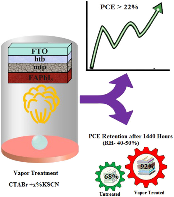
1. Introduction
Common perovskite solar cells now have recorded a high efficiency of 25.8%, thanks to their unique optoelectronic properties.1,2 Perovskite materials with a small exciton binding energy are qualified for light harvesting tasks in solar cells. They quickly generate free photo carriers. Their high defect tolerance property guarantees the generation of a photo-current. Shockley–Queisser's theory indicates high-performance perovskite solar cells (PSCs) are accessible. But fabrication engineering is needed to avoid interfaces and bulk losses in the perovskite solar cell device and prepare highly efficient PSCs. Formamidinium lead iodide (FAPbI3) perovskite with desirable photovoltaic properties has been used in the literature to form efficient PSCs.1,3–5 Highly crystalline, stable, and pure α-phase FAPbI3 films are vital requirements for solar cell application. Usually, FAPbI3 readily transfers from its photoactive α-phase to a photo-inactive δ-phase at temperatures lower than 150 °C.4,6 Researchers have mixed FA+ cations with MA+, Cs+, K+, and Rb+ to address this issue and introduced new double, triple, and quadruple cation PSCs.7–10 Mixed cation–anion perovskites while increasing the phase stability of FAPbI3 perovskite generate other disadvantages such as low thermal stability, phase separation, and tight absorbance spectrum.11–14 The broadened band-gap energy of mixed cation–anion perovskite systems reduces the number of photo-carriers and causes a lower photovoltaic performance in related PSCs than the pure FAPbI3 PSCs. In addition, the incorporation of different cations with various ionic radii may induce a local strain and generate a distorted perovskite structure.15,16
In recent years, researchers developed new approaches to increase the phase stability of FAPbI3 perovskite while keeping its optical and crystalline properties. Min et al.4 incorporated methylenediammonium (MDA) cations into the FAPbI3 structure to stabilize its α-phase. They showed forasmuch as ionic radii of MDA+ and FA+ are comparable, the absorbance edge position doesn't change, while more H groups of MDA+ induce ionic interaction and stabilize the α-phase of FAPbI3. Lu et al. employed methylammonium thiocyanate (MASCN) vapor to convert the δ-phase to the desired α-phase. They found that SCN− ions promote the formation and stabilization of a-FAPbI3. Jeong et al.3 introduced formate anion (HCOO−) to boost the α-FAPbI3 crystallinity. They showed that HCOO− ions fill anion vacancies and brought a PCE of 25.6%. They proved that HCOO− ions have more binding affinity for iodide vacancies than the other halides of Cl−, Br−, and BF4−. Park et al.17 added 15% of isopropylammonium chloride into the FAPbI3 pre-solution and observed that remaining isopropylammonium cations at the grain boundaries (Gbs) assist in the stabilization of the α-FAPbI3 structure. If organic ammonium halides employed as a passivation agent for surface treatment, not additive into the bulk of FAPbI3, are good candidates for α-phase stabilization along with improving humidity stability. Liu et al.18 used iso-butylammonium iodide to post-treat of FAPbI3 perovskite. They found iso-butylammonium cations induce undesirable δ-FAPbI3 to α-FAPbI3 and also efficiently passivate electronic trap states near to the FAPbI3 surface, improving the optoelectronic FAPbI3 film. Jeong et al.19 employed cyclohexylammonium iodide to passivate FAPbI3 Gbs and form a 2D/3D heterostructure. They deduced that FA+ ions on the 3D FAPbI3's surfaces are dissolved during the surface treatment, and cyclohexylammonium-based cations are reacted with the PbI2, forming 2D perovskites over FAPbI3 layer. Shen et al.20 introduced sulfonyl fluoride-functionalized phenethylammonium (SF-PEA) salt as surface functionalization for a FAPbI3 layer while maintaining its Eg value. They concluded SF-PEA not only passivates the surface defects but also protects the perovskite from phase transition.
The aforementioned discussions encouraged us to stabilize the α-phase of FAPbI3 with a new strategy. Our method not only improves phase stability but also increases the humidity stability of the FAPbI3 layer along with its photovoltaic efficiency. We exposed cetrimonium bromide + 5% potassium thiocyanate (CTABr + 5% KSCN) vapor to the FAPbI3 layer during its fabrication process. The vapor post-treatment vanishes δ-phase in the FAPbI3 layer. Introduction of CTA+ along with SCN− ions stitch Gbs in the FAPbI3 layer, resulting in PSCs with lower defect losses. The vapor post-treatment boosts the carriers' lifetime in the FAPbI3 and facilitates charge transport with a band alignment phenomenon. The vapor-treated PSCs bring a champion efficiency of 22.34%, higher than the 20.11% efficiency obtained for control PSCs. In addition, the stabilized and hydrophobic α-FAPbI3 PSCs show an improved stability behavior.
2. Experimentals
2.1. Deposition of hole blocking titanium dioxide (h-TiO2) layer
In vial A, 10 mL of isopropyl alcohol (IPA, ≥99.7%, Sigma Aldrich) and 70 μL HCl (2 M) are mixed for 20 min in an ice bath. In vial B, 750 μL of tetraisopropyl orthotitanate (TTIP, ≥97%, Sigma Aldrich) is mixed with 10 mL of IPA for 20 min in the ice bath. Vial A solution is dropwise added into vial B. The final solution is stirred in the ice bath for 20 min and a further 15 min at room temperature (RT). The obtained solution is filtered with a 0.2 μm PTFE filter. 60 μL of the filtered solution is poured on pre-patterned FTO and spin-coated at 2000 rpm for 30 s. h-TiO2 layers are dried in an oven at 100 °C for 5 min and then baked for 30 min at 450 °C.
2.2. Deposition of mesoporous titanium dioxide (m-TiO2) layer
400 mg of titanium dioxide paste (MPT-20 Titania Paste, Greatcell Solar) is diluted with 2652 mg of ethanol (EtOH, 99.9%, Merck) and 75 mg of terpineol (Merck, 98%). The obtained solution is stirred overnight at RT. 75 μL of m-TiO2 pre-solution is dropped on the h-TiO2 layer and spin-coated at 3000 rpm for 25 s. After the spin-coating process, mtp layers are dried at a temperature of 100 °C for 5 min and sintered for 60 min at 500 °C.
2.3. Deposition of perovskite layer
Formamidinium lead triiodide (FAPbI3) pre-solution is synthesized as follows. At first, 737.2 mg of lead iodide (PbI2, 99.999%, Sigma Aldrich) is dissolved in 890 μL of N,N-dimethylformamide (DMF, 99.8%, Sigma Aldrich) and 110 μL of dimethyl sulfoxide (DMSO, 99.9%, Sigma Aldrich). The PbI2 solution is stirred at 75 °C for 45 min and then is cooled down to RT. In the following, 275.2 mg formamidinium iodide (FAI, 99.99%, Greatcell solar) and 33 mg methylammonium chloride (MACl, 99.99%, Greatcell solar) are poured into the cooled PbI2 solution, followed by stirring at RT for 30 min. 80 μL of FAPbI3 pre-solution is spin-coated on the m-TiO2 layer with a speed of 1000 rpm for 3 s and then 6000 rpm for 30 s. During the second step, 150 μL chlorobenzene (CB, 99.9%, Sigma Aldrich) anti-solvent is poured on the FAPbI3 layer to assist the perovskite crystallization process. FAPbI3 perovskite layers are post-annealed at 100 °C for 1 min and 155 °C for 15 min.
2.4. Vapor-assisted deposition (VAD)
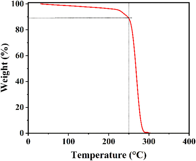
FAPbI3 layers are treated with a cetrimonium bromide (CTABr, 99%, Sigma Aldrich) + x(0–10)% potassium thiocyanate (KSCN, 99%, Sigma Aldrich) vapor during the fabrication process to improve the surface quality. For this aim, 5 mg of CTABr + x% KSCN materials are heated at 250 °C and its vapor is guided toward the pre-annealed FAPbI3 layer for 10 min. It should be mentioned the addition of KSCN is in a weight ratio of CTABr. Temperature of 250 °C was chosen to heat the powders to guarantee decomposition of both CTABr and KSCN materials. To better insight, TGA curve of CTABr-5% KSCN powder has been shown in Fig. 1. Before employing VAD treatment, perovskite layers are first post-annealed at 100 °C for 1 min and 155 °C for 8 min, then vapor directed toward them.
Fig. 1. TGA test of CTABr-5% KSCN powder at rate of 10 °C min−1.
2.4.1. Deposition of hole transport layer
2,2′,7,7′-Tetrakis(N,N-di-p-methoxyphenylamino)-9,9′-spirobifluorene (spiro-OMeTAD, 99.8%, Lumtec) as a hole transfer material (HTM) is dissolved in CB to prepare a 40 mg mL−1 solution. The spiro-OMeTAD solution is doped with 39 μL of 4-tert-butylpyridine (tBP, 98%, Sigma Aldrich), 23 μL of bis(trifluoromethylsulfonyl)amine lithium (Li-TFSI, 99.95%, Sigma Aldrich) stock solution in acetonitrile (ACN, 99.8%, Sigma Aldrich) (516 mg mL−1), and 10 μL of stock solution of tris(2-(1H-pyrazol-1-yl)-4-tert-butylpyridine)-cobalt(iii)tris(bis(trifluoromethylsulfonyl)imide) (FK209 Co(iii) TFSI, 99%, Lumtec) in ACN (400 mg mL−1). 70 μL of spiro-OMeTAD pre-solution is deposited on the FAPbI3 perovskite layer by spin-coating at speed of 4000 rpm for 30 s. To study humidity stability of devices, poly[bis(4-phenyl)(2,4,6-trimethylphenyl)amine] (PTAA, Lumtec) is used as HTM. 15 mg of the PTAA material is dissolved in 1 mL of toluene (99.8%, Sigma Aldrich) contains 5 mol% of a tris(pentafluorophenyl)borane (BCF, 98%, TCI) additive. 70 μL of PTAA solution is spin-coated over the FAPbI3 layer with a speed of 3000 rpm.
2.5. Deposition of back electrodes
To complete the perovskite solar cell structure, gold electrodes with a thickness of 80 nm are thermally evaporated over the HTM layers at a high vacuum level with a controlled deposition rate of 1 Å s−1.
2.6. Measurements
FAPbI3 X-ray diffraction (XRD) patterns were investigated via a Brucker XRD spectrometer (D2 Phaser). Perovskite morphologies were monitored by FE-SEM micrographs recorded by Mira3, TESCAN FE-SEM equipment. Ultraviolet-visible absorbance spectrum of FAPbI3 films was measured via a UV-2600i spectrometer (Shimadzu). A HORIBA Fl-1039/40 Fluorolog spectrometer was employed to collect the photoluminescence (PL) emission of excited FAPbI3 layers with a 450 nm diode laser. Time-resolved PL (TRPL) decay traces of FAPbI3 films on the glass substrate were collected at 805 nm with Horiba Fluorolog single photon counting system with exciting the FAPbI3 films with a 532 nm pulsed laser excitation. The current–voltage (I–V) responses of FAPbI3 solar cells under simulated illumination of AM 1.5G were conducted with a source meter (Keithley 2400). The active area of solar cells for I–V measurements was 0.1 cm2. A calibrated Oriel ClassAAA solar simulator was employed as a light source for I–V tests. Capacitance–voltage (C–V) tests were measured via a VMP3, Biologic potentiometer device at a constant 10 kHz frequency from −0.2 to 1.1 V to gain the Mott–Schottky curves. UPS of FAPbI3 films was measured using a Thermo Fisher ESCALAB 250XL instrument with a monochromatic 21.22 eV He I light source.
3. Results
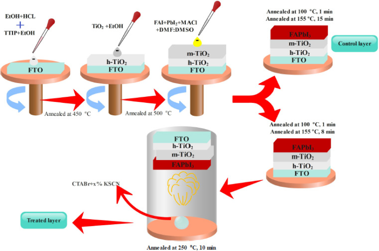
Here, we introduce an efficient method to vanish the photo inactive FAPbI3 phase. In addition, the suggested approach boosts the photovoltaic (PV) efficiency and stability of FAPbI3 PSCs. As shown in Fig. 2, the CTABr material is vaporized over the FAPbI3 layer during the fabrication process. In continue, to further improve the PV performance of PSCs, the KSCN material as an additive is employed for the CTABr. In this step, different CTABr + x% KSCN (x = 0–7.5) mixed materials are prepared and vapor-treated the FAPbI3 layers. Later, more discussion is involved to clarify the vapor-treatment effects on FAPbI3 PSCs. From here onwards, untreated, treated with a vapor of CTABr, and treated with a vapor of CTABr-5% KSCN perovskite layers are labeled with control, CTABr-0%, and CTABr-5%, respectively. Fig. 2 schematically shows our employed method to fabricate different FAPbI3 layers.
Fig. 2. Schematic view for fabrication of control and vapor treated FAPbI3 layers.
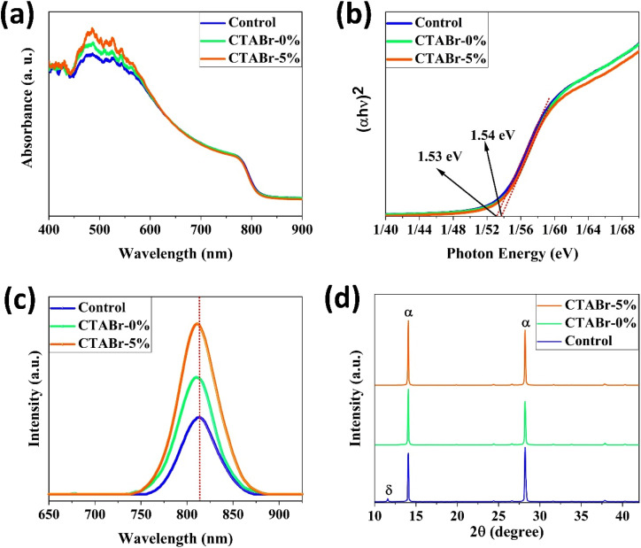
Fig. 3(a) shows absorbance spectra of control, CTABr-0%, and CTABr-5% FAPbI3 films. Fig. 3(b) illustrates related Tauc curves to measure band-gap energy (Eg) of different FAPbI3 layers. It is observed that vapor post-treated CTABr-5% FAPbI3 has the highest light harvesting behavior than the control and CTABr-0% perovskite layers. Therefore, the CTABr-5% layer has the potential to record higher photo-current in related FAPbI3 PSCs. In addition, Tauc plots represent a light blue shift in Eg value from 1.53 eV to 1.54 eV after conducting vapor post-treatment with CTABr or CTABr + 5% KSCN. It could be due to the slight diffusion of bromine ions (Br−) and or thiocyanate ions (SCN−).21,22 Steady-state photoluminescence (PL) curves of different FAPbI3 layers have been shown in Fig. 3(c). Responses show an increment in the intensity of PL peak for the CTABr-5% layer compared to the CTABr-0% and control FAPbI3 layers, suggesting the prevented non-radiative charge recombination.23,24 Later would be shown that the surface passivation caused by vapor treatment is a reason for the lower non-radiative charge recombination in the CTABr-5% FAPbI3 layer. The collected X-ray diffraction (XRD) patterns of FAPbI3 perovskite layers are shown in Fig. 3(d) to study the effects of vapor treatment on the FAPbI3 crystalline properties. XRD patterns show two main peaks at 2θ = 14.07° and 28.21° corresponding to (001) and (002) plane orientation of the α-FAPbI3 phase.3 It indicates the addition of 35 mol% of MACl forms well-oriented perovskite layers. In diffracted XRD peaks of the control layer, an additional peak at 2θ = 11.59° assigned to the δ-FAPbI3 phase is observed, while it is removed in the treated FAPbI3 layers with vapors. In addition, the vapor of CTABr + 5% KSCN more effectively intensifies XRD signals and increases FAPbI3 crystallinity.25 We monitored full width at half maximum (FWHM) of (001) XRD peak for all layers. Fitted values of 0.1202, 0.1039, and 0.0981 were obtained for the control, CTABr-0%, and CTABr-5% FAPbI3 layers, respectively. It indicates that vapors of CTABr and CTABr + 5% KSCN increase FAPbI3 grains size.26,27
Fig. 3. (a) Ultraviolet-visible absorbance spectra, (b) related Tauc curves, (c) photoluminescence spectra, and (d) X-ray diffraction patterns of different FAPbI3 layers.
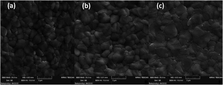
FESEM micro-images of FAPbI3 layers are depicted in Fig. 4 to investigate their micromorphology. Fig. 4(a) shows the control layer has miro-sized grains with obvious grain boundaries (Gbs). Exposing CTABr vapor on the FAPbI3 during the fabrication process enlarged perovskite grains, leading to lower surface defects in the FAPbI3 layer (Fig. 4(b)). Employing the mixed vapor of CTABr + 5% KSCN further enlarged the perovskite grain (Fig. 4(c)). CTABr + 5% KSCN vapor well-passivated Gbs and reduced charge accumulation center in the FAPbI3 surface. The enlarged perovskite grains reveal better photo-carriers extraction at the perovskite/HTL interface and assist in the performance improvement of PSCs. Indeed, the passivated Gbs along with enlarged grains in the CTABr-5% FAPbI3 layer are responsible for the boosted light-harvesting (see Fig. 3(a)) and the reduced non-radiative charge recombination (see Fig. 3(c)) observed in it.
Fig. 4. FESEM micro-images of (a) control, (b) CTABr-0%, and (c) CTABr-5% vapor-treated FAPbI3 layers.
In the following, we fabricated FAPbI3 PSCs with or without vapor treatment steps to investigate the effects of vapors on the PV properties of PSCs. The calculated PV parameters from J–V characterizations are listed in Table 1. J–V curves of best-performance PSCs in each group of control, CTABr-0%, and CTABr-5% are depicted in Fig. 5(a). For the control PSCs, maximum efficiency of 19.48% with an open-circuit voltage (VOC) of 1.110 V, a filling factor of 79.63%, and a short-circuit current density (JSC) of 21.58 mA cm−2 was recorded. By applying CTABr vapor on the FAPbI3 perovskite layer, the efficiency of FAPbI3 PSCs reached up to 20.49% assigned to a VOC of 1.130 V, a FF of 80.69%, and a JSC of 22.47 mA cm−2. Fig. 5(b–e) show statistical distribution of fabricated solar cells in each group to find information on reproducibility of fabrication process. As listed results in Table 1 show, among vapors of CTABr + 2.5%, 5%, 7.5% KSCN, CTABr + 5% KSCN vapor forms more desirable FAPbI3 for PV application and give raises higher PV parameters. By exposing CTABr + 5% KSCN on the FAPbI3 layers, a champion efficiency of 22.05% assigned to a VOC of 1.170 V, a FF of 82.11%, and a JSC of 22.95 mA cm−2 was recorded for CTABr-5% PSCs. Fig. 5(f) shows the IPCE spectrum for different FAPbI3 PSCs. The integrated JSC are 21.47, 21.88, and 22.54 mA cm−2 for the control, CTABr-0%, and CTABr-5% FAPbI3 PSCs, respectively. The integrated JSC from IPCE spectra are in agreement with JSC recorded from the J–V tests (see Table 1).
J–V photovoltaic values of FAPbI3-based solar cells post-treated with different vapors of cetrimonium bromide + x% potassium thiocyanate (CTABr-x%).
| Device name | V OC (V) | J SC (mA cm−2) | FF (%) | PCE (%) | |
|---|---|---|---|---|---|
| Control | Average | 1.098 ± 0.019 | 21.58 ± 30 | 78.52 ± 0.80 | 18.61 ± 0.51 |
| Best | 1.110 | 22.04 | 79.63 | 19.48 | |
| CTABr-0.0% | Average | 1.116 ± 0.016 | 21.89 ± 0.37 | 79.99 ± 0.49 | 19.55 ± 0.53 |
| Best | 1.130 | 22.47 | 80.69 | 20.49 | |
| CTABr-2.5% | Average | 1.128 ± 0.020 | 22.38 ± 0.19 | 80.60 ± 0.52 | 20.35 ± 0.45 |
| Best | 1.150 | 22.62 | 80.75 | 21.01 | |
| CTABr-5.0% | Average | 1.152 ± 0.015 | 22.49 ± 0.32 | 82.10 ± 0.43 | 21.27 ± 0.51 |
| Best | 1.170 | 22.95 | 82.11 | 22.05 | |
| CTABr-7.5% | Average | 1.148 ± 0.015 | 22.37 ± 0.43 | 80.41 ± 0.67 | 20.66 ± 0.68 |
| Best | 1.170 | 23.05 | 80.57 | 21.72 |
Fig. 5. (a) J–V curves of best-performance of different FAPbI3-based solar cells. Box statistical distribution of (b) open-circuit voltage (VOC), (c) short-circuit current density (JSC), (d) fill factor (FF) and (e) power conversion efficiency (PCE) for different perovskite solar cells. (f) Incident photon-to-current efficiency curves of solar cells and related integrated current densities.
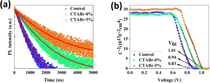
To find origin of PV improvements, TRPL, C–V, and UPS tests were conducted. Fig. 6(a) shows TRPL of different FAPbI3 layers to investigate their charges lifetime. TRPL decay plots are fitted with a bi-exponential equation, as follow:
 |
1 |
Fig. 6. (a) Time-resolved photoluminescence of FAPbI3 films coated on glass substrates. Red solid lines indicate curves fitting with a bi-exponential equation. (b) Mott–Schottky curves of FAPbI3 solar cells based on different FAPbI3 layers.
In eqn (1), τ1 and τ2 indicate the fast and slow decay times. A1 and A2 indicate the fast and slow decay amplitudes. The average carrier lifetime (τavg) is calculated using 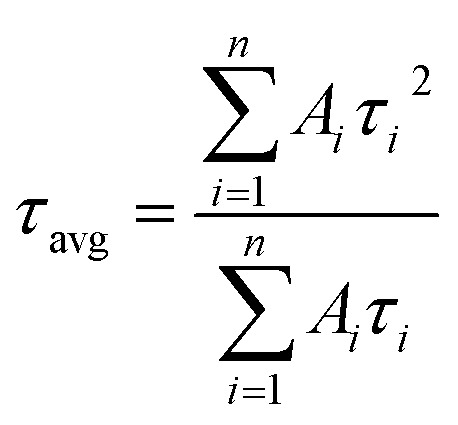 formula. Carrier lifetimes and amplitudes were listed in Table 2. τavg of 713.94, 1324.34, and 1675.31 ns were measured for the control, CTABr-0%, and CTABr-5% FAPbI3 layers, respectively. The fast decay is related to non-radiative charge recombination due to deep charge trapping in the FAPbI3 layer. Slow decay refers to free carriers' radiative recombination processes.15,28 Both τ1 and τ2 with vaporizing of CTABr over the control layer are increased, and with the assistance of KSCN, these values are further boosted. The increased carrier lifetime refers to reduced non-radiative charge recombination by reducing the trap states in the FAPbI3.29 In addition, as summarized results in Table 2 show, employing vapor treatment reduces the A1 proportion in the TRPL profile of the FAPbI3 layer. It connotes reduced structural defects in the perovskite layer, consistent with the enlarged perovskite grains (see Fig. 4).30,31 Higher VOC and FF recorded for the CTABr-5% PSCs are due to longer carriers' lifetime measured in them.
The results obtaining from the fitting of the time resolve photoluminescence of the control, CTABr-0%, and CTABr-5% formamidinium lead iodide (FAPbI3) layers on the glass substrates. Control, CTABr-0%, and CTABr-5% allude to untreated, cetrimonium bromide vapor-treated, and cetrimonium bromide + 5% potassium thiocyanate treated FAPbI3 layers.
| Perovskite | τ 1 (ns) | A 1 (%) | τ 2 (ns) | A 2 (%) | τ avg (ns) |
|---|---|---|---|---|---|
| Control | 09.54 | 16.50 | 0715.81 | 83.50 | 0713.94 |
| CTABr-0% | 17.00 | 13.57 | 1326.97 | 86.43 | 1324.34 |
| CTABr-5% | 19.55 | 08.38 | 1677.07 | 91.62 | 1675.31 |
Fig. 6(b) shows the C−2–V curves for control, CTABr-0%, and CTABr-5% FAPbI3 PSCs. The Mott–Schottky formula (eqn (2)) was employed for fitting C−2–V curves to measure built-in potential (Vbi) in the depletion region:
 |
2 |
In eqn (2), A is the PSCs' active area, N is carrier density, e is electron charge, KB is Boltzmann constant, T is temperature of test condition, V is applied voltage, ε0 is vacuum permittivity, and εr is dielectric constant of FAPbI3. As specified in C−2–V plots, the CTABr vapor enhances Vbi of FAPbI3 PSCs from 0.83 V to 0.94 V. In the next step, applying CTABr + 5% KSCN vapor on the FAPbI3 layer improves Vbi up to 1.01 V. The boosted Vbi in FAPbI3 PSCs implies to a stronger driving force to charge separation, resulting in increased carrier extraction to electrodes and enhanced JSC.
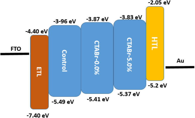
In addition, the ultraviolet photoelectron spectroscopy (UPS) test was utilized to investigate the possible band alignment phenomenon between energy levels of different FAPbI3 layers and HTL. The UPS spectra are depicted in Fig. 7 and the analyzed results are summarized in Table 3. The valence band of control, CTABr-0%, and CTABr-5% FAPbI3 layers are −5.49, −5.41, and −5.37 eV. The valence band energy reported for spiro-OMeTAD is −5.2 eV.32,33 Therefore, the CTABr + 5% KSCN vapor nears the valence band energy of FAPbI3 to the spiro-OMeTAD value and enhances the hole transfer from the FAPbI3 to HTL along with preventing the electron transportation at the interface of FAPbI3/HTL. The impact of vapor treatment on band positioning of perovskite layer is shown in Fig. 8.
Fig. 7. UPS spectrum of control, CTABr-0%, and CTABr-5% FAPbI3 films.
The band structure parameters of control, CTABr-0%, and CTABr-5% FAPbI3 layers. Eg indicates energy bandgap of layers and obtained from Tauc curves; VBM indicates valence band maximum; Ws indicates the work function of layers; Ec indicates conduction band edge; Ev refers valence band edge.
| Sample name | E g (eV) | VBM (eV) | W s (eV) | E v (eV) | E c (eV) |
|---|---|---|---|---|---|
| Control | 1.53 | −1.61 | −3.88 | −5.49 | −3.96 |
| CTABr-0% | 1.54 | −1.60 | −3.81 | −5.41 | −3.87 |
| CTABr-5% | 1.54 | −1.65 | −3.72 | −5.37 | −3.83 |
Fig. 8. Impact on band positioning after vapor treatment.
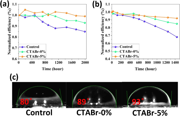
In the end, we conducted stability tests in two environments with relative humidity levels of <20% (Fig. 9(a)) and 40–50% (Fig. 9(b)) to investigate the effects of the vapor treatment approach on the stability behavior of FAPbI3 layers. Among control, CTABr-0%, and CTABr-5% PSCs, the CTABr-5% device shows higher shelf stability, remaining 99% of its initial efficiency during 1992 h aging time, higher than 93% in the CTABr-0% and 85% in the control devices (see Fig. 9(a)). Higher shelf stability observed in the CTABr-5% FAPbI3 correlates with higher phase and structural stabilities in the CTABr-5% FAPbI3, which is supported by its intensified α-phase (see Fig. 3(d)). In addition, CTABr-5% FAPbI3 device shows higher resistance against humidity than the other devices. The CTABr-5% device keeps 92% of its initial efficiency after 1440 h, while CTABr-0% and control devices keep 85% and 68% of their efficiency during stability test (see Fig. 9(b)). Fig. 9(c) shows the contact angle of water droplets on the control, CTABr-0%, and CTABr-5% FAPbI3 layers. Contact angles are 80°, 89°, and 93°. The enlarged contact angle achieved for the CTABr-5% refers to its improved humidity resistance.34 The hydrophobic nature of the long chain CTABr material brings a waterproof FAPbI3 layer and prevents FAPbI3 degradation. The passivated Gbs is another reason for the higher humidity stability observed in the CTABr-5% FAPbI3 PSCs.35,36
Fig. 9. Efficiency tracking of the unsealed FAPbI3 solar cells based on control, CTABr-0%, and CTABr-5% FAPbI3 layers in (a) a dry box with humidity level of lower than 20%, and in (b) ambient air with relative humidity of 40–50% at room temperature in dark condition. (c) Water droplet angle on the control, CTABr-0%, and CTABr-5% FAPbI3 layers.
4. Conclusion
We introduced a vapor-based treatment approach to modify FAPbI3 formation and fabricate a pure α-FAPbI3 phase perovskite layer. During the fabrication process of the FAPbI3 layer, we vaporized the CTABr + 5% KSCN on it. This way improved the PV efficiency and stability of fabricated PSCs. It was observed that the vapor of CTABr + 5% KSCN simultaneously enlarges FAPbI3 grains and passivates perovskite Gbs. It generates a favorable FAPbI3 layer for solar cell devices. The vapor treatment step reduces the trap-assisted charge recombination in the FAPbI3 layer and elongates the carriers' lifetime. In addition, a band alignment occurred between the valence band of FAPbI3 and HTL, resulting in facilitated hole transfer at FAPbI3/HTL interface. As a result, the CTABr + 5% KSCN vapor fabricates PSCs with a champion efficiency of 22.34%, higher than the efficiency of 19.48% for the control PSCs. In addition, the CTABr-5% FAPbI3 solar cells had higher structural and humidity stabilities than the control devices.
Conflicts of interest
The authors declare that they have no conflict of interest.
Supplementary Material
References
- Min H. Lee D. Y. Kim J. Kim G. Lee K. S. Kim J. Paik M. J. Kim Y. K. Kim K. S. Kim M. G. Perovskite solar cells with atomically coherent interlayers on SnO2 electrodes. Nature. 2021;598:444–450. doi: 10.1038/s41586-021-03964-8. [DOI] [PubMed] [Google Scholar]
- Mohseni H. R. Dehghanipour M. Dehghan N. Tamaddon F. Ahmadi M. Sabet M. Behjat A. Enhancement of the photovoltaic performance and the stability of perovskite solar cells via the modification of electron transport layers with reduced graphene oxide/polyaniline composite. Sol. Energy. 2021;213:59–66. [Google Scholar]
- Jeong J. Kim M. Seo J. Lu H. Ahlawat P. Mishra A. Yang Y. Hope M. A. Eickemeyer F. T. Kim M. Pseudo-halide anion engineering for α-FAPbI 3 perovskite solar cells. Nature. 2021;592:381–385. doi: 10.1038/s41586-021-03406-5. [DOI] [PubMed] [Google Scholar]
- Min H. Kim M. Lee S.-U. Kim H. Kim G. Choi K. Lee J. H. Seok S. I. Efficient, stable solar cells by using inherent bandgap of α-phase formamidinium lead iodide. Science. 2019;366:749–753. doi: 10.1126/science.aay7044. [DOI] [PubMed] [Google Scholar]
- Lu H. Liu Y. Ahlawat P. Mishra A. Tress W. R. Eickemeyer F. T. Yang Y. Fu F. Wang Z. Avalos C. E. Vapor-assisted deposition of highly efficient, stable black-phase FAPbI3 perovskite solar cells. Science. 2020;370:eabb8985. doi: 10.1126/science.abb8985. [DOI] [PubMed] [Google Scholar]
- Koh T. M. Fu K. Fang Y. Chen S. Sum T. C. Mathews N. Mhaisalkar S. G. Boix P. P. Baikie T. Formamidinium-containing metal-halide: an alternative material for near-IR absorption perovskite solar cells. J. Phys. Chem. C. 2014;118:16458–16462. [Google Scholar]
- Mohammed M. K. A. Shalan A. E. Dehghanipour M. Mohseni H. R. Improved mixed-dimensional 3D/2D perovskite layer with formamidinium bromide salt for highly efficient and stable perovskite solar cells. Chem. Eng. J. 2022;428:131185. [Google Scholar]
- Bu T. Liu X. Zhou Y. Yi J. Huang X. Luo L. Xiao J. Ku Z. Peng Y. Huang F. A novel quadruple-cation absorber for universal hysteresis elimination for high efficiency and stable perovskite solar cells. Energy Environ. Sci. 2017;10:2509–2515. [Google Scholar]
- Reza K. M. Gurung A. Bahrami B. Chowdhury A. H. Ghimire N. Pathak R. Rahman S. I. Laskar M. A. R. Chen K. Bobba R. S. Grain Boundary Defect Passivation in Quadruple Cation Wide-Bandgap Perovskite Solar Cells. Sol. RRL. 2021;5:2000740. [Google Scholar]
- Gutierrez-Partida E. Hempel H. Caicedo-Davila S. Raoufi M. Pena-Camargo F. Grischek M. Gunder R. Diekmann J. Caprioglio P. Brinkmann K. O. Large-grain double cation perovskites with 18 μs lifetime and high luminescence yield for efficient inverted perovskite solar cells. ACS Energy Lett. 2021;6:1045–1054. [Google Scholar]
- Gao X. X. Luo W. Zhang Y. Hu R. Zhang B. Züttel A. Feng Y. Nazeeruddin M. K. Stable and high-efficiency methylammonium-free perovskite solar cells. Adv. Mater. 2020;32:1905502. doi: 10.1002/adma.201905502. [DOI] [PubMed] [Google Scholar]
- Smecca E. Numata Y. Deretzis I. Pellegrino G. Boninelli S. Miyasaka T. La Magna A. Alberti A. Stability of solution-processed MAPbI 3 and FAPbI 3 layers. Phys. Chem. Chem. Phys. 2016;18:13413–13422. doi: 10.1039/c6cp00721j. [DOI] [PubMed] [Google Scholar]
- Shao Z. Meng H. Du X. Sun X. Lv P. Gao C. Rao Y. Chen C. Li Z. Wang X. Cs4PbI6-Mediated Synthesis of Thermodynamically Stable FA0. 15Cs0. 85PbI3 Perovskite Solar Cells. Adv. Mater. 2020;32:2001054. doi: 10.1002/adma.202001054. [DOI] [PubMed] [Google Scholar]
- Gil-Escrig L. Dreessen C. Palazon F. Hawash Z. Moons E. Albrecht S. Sessolo M. Bolink H. J. Efficient wide-bandgap mixed-cation and mixed-halide perovskite solar cells by vacuum deposition. ACS Energy Lett. 2021;6:827–836. doi: 10.1021/acsenergylett.0c02445. [DOI] [PMC free article] [PubMed] [Google Scholar]
- Kim G. Min H. Lee K. S. Lee D. Y. Yoon S. M. Seok S. I. Impact of strain relaxation on performance of α-formamidinium lead iodide perovskite solar cells. Science. 2020;370:108–112. doi: 10.1126/science.abc4417. [DOI] [PubMed] [Google Scholar]
- Rolston N. Bush K. A. Printz A. D. Gold-Parker A. Ding Y. Toney M. F. McGehee M. D. Dauskardt R. H. Engineering stress in perovskite solar cells to improve stability. Adv. Energy Mater. 2018;8:1802139. [Google Scholar]
- Park B.-w. Kwon H. W. Lee Y. Lee D. Y. Kim M. G. Kim G. Kim K.-j. Kim Y. K. Im J. Shin T. J. Stabilization of formamidinium lead triiodide α-phase with isopropylammonium chloride for perovskite solar cells. Nat. Energy. 2021;6:419–428. [Google Scholar]
- Liu Y. Akin S. Hinderhofer A. Eickemeyer F. T. Zhu H. Seo J. Y. Zhang J. Schreiber F. Zhang H. Zakeeruddin S. M. Stabilization of highly efficient and stable phase-pure FAPbI3 perovskite solar cells by molecularly tailored 2D-overlayers. Angew. Chem., Int. Ed. 2020;59:15688–15694. doi: 10.1002/anie.202005211. [DOI] [PubMed] [Google Scholar]
- Jeong S. Seo S. Yang H. Park H. Shin S. Ahn H. Lee D. Park J. H. Park N. G. Shin H. Cyclohexylammonium-Based 2D/3D Perovskite Heterojunction with Funnel-Like Energy Band Alignment for Efficient Solar Cells (23.91%) Adv. Energy Mater. 2021:2102236. [Google Scholar]
- Shen C. Wu Y. Zhang S. Wu T. Tian H. Zhu W.-H. Han L. Stabilizing formamidinium lead iodide perovskite by sulfonyl-functionalized phenethylammonium salt via crystallization control and surface passivation. Sol. RRL. 2020;4:2000069. [Google Scholar]
- Martynow M. Głowienka D. Galagan Y. Guthmuller J. Effects of Bromine Doping on the Structural Properties and Band Gap of CH3NH3Pb (I1–xBrx) 3 Perovskite. ACS Omega. 2020;5:26946–26953. doi: 10.1021/acsomega.0c04406. [DOI] [PMC free article] [PubMed] [Google Scholar]
- Peña-Camargo F. Caprioglio P. Zu F. Gutierrez-Partida E. Wolff C. M. Brinkmann K. Albrecht S. Riedl T. Koch N. Neher D. Halide segregation versus interfacial recombination in bromide-rich wide-gap perovskite solar cells. ACS Energy Lett. 2020;5:2728–2736. [Google Scholar]
- Dehghanipour M. Behjat A. Bioki H. A. Fabrication of stable and efficient 2D/3D perovskite solar cells through post-treatment with TBABF4. J. Mater. Chem. C. 2021;9:957–966. [Google Scholar]
- Tan S. Yavuz I. Weber M. H. Huang T. Chen C.-H. Wang R. Wang H.-C. Ko J. H. Nuryyeva S. Xue J. Shallow iodine defects accelerate the degradation of α-phase formamidinium perovskite. Joule. 2020;4:2426–2442. [Google Scholar]
- Yang C. Wang H. Miao Y. Chen C. Zhai M. Bao Q. Ding X. Yang X. Cheng M. Interfacial molecular doping and energy level alignment regulation for perovskite solar cells with efficiency exceeding 23. ACS Energy Lett. 2021;6:2690–2696. [Google Scholar]
- Zhou T. Lai H. Liu T. Lu D. Wan X. Zhang X. Liu Y. Chen Y. Highly efficient and stable solar cells based on crystalline oriented 2D/3D hybrid perovskite. Adv. Mater. 2019;31:1901242. doi: 10.1002/adma.201901242. [DOI] [PubMed] [Google Scholar]
- Xu F. Liu J. Subbiah A. S. Liu W. Kang J. Harrison G. T. Yang X. Isikgor F. H. Aydin E. De Bastiani M. Potassium Thiocyanate-Assisted Enhancement of Slot-Die-Coated Perovskite Films for High-Performance Solar Cells. Small Sci. 2021;1:2000044. [Google Scholar]
- Lee J.-W. Tan S. Han T.-H. Wang R. Zhang L. Park C. Yoon M. Choi C. Xu M. Liao M. E. Solid-phase hetero epitaxial growth of α-phase formamidinium perovskite. Nat. Commun. 2020;11:1–11. doi: 10.1038/s41467-020-19237-3. [DOI] [PMC free article] [PubMed] [Google Scholar]
- Li F. Deng X. Qi F. Li Z. Liu D. Shen D. Qin M. Wu S. Lin F. Jang S.-H. Regulating surface termination for efficient inverted perovskite solar cells with greater than 23% efficiency. J. Am. Chem. Soc. 2020;142:20134–20142. doi: 10.1021/jacs.0c09845. [DOI] [PubMed] [Google Scholar]
- Nagaraj G. Mohammed M. K. A. Shekargoftar M. Sasikumar P. Sakthivel P. Ravi G. Dehghanipour M. Akin S. Shalan A. E. High-performance perovskite solar cells using the graphene quantum dot-modified SnO2/ZnO photoelectrode. Mater. Today Energy. 2021;22:100853. [Google Scholar]
- Su H. Zhang J. Hu Y. Du X. Yang Y. You J. Gao L. Liu S. Fluoroethylamine Engineering for effective passivation to attain 23.4% efficiency perovskite solar cells with superior stability. Adv. Energy Mater. 2021;11:2101454. [Google Scholar]
- He Z. Zhou Y. Xu C. Su Y. Liu A. Li Y. Gao L. Ma T. Mechanism of Enhancement in Perovskite Solar Cells by Organosulfur Amine Constructed 2D/3D Heterojunctions. J. Phys. Chem. C. 2021;125:16428–16434. [Google Scholar]
- Akman E. Akin S. Poly(N,N′-bis-4-butylphenyl-N,N′-bisphenyl) benzidine-based interfacial passivation strategy promoting efficiency and operational stability of perovskite solar cells in regular architecture. Adv. Mater. 2021;33:2006087. doi: 10.1002/adma.202006087. [DOI] [PubMed] [Google Scholar]
- Zhang Y. Li Y. Zhang L. Hu H. Tang Z. Xu B. Park N. G. Propylammonium Chloride Additive for Efficient and Stable FAPbI3 Perovskite Solar Cells. Adv. Energy Mater. 2021:2102538. [Google Scholar]
- Dehghanipour M. Behjat A. Shabani A. Haddad M. Toward desirable 2D/3D hybrid perovskite films for solar cell application with additive engineering approach. J. Mater. Sci.: Mater. Electron. 2022:1–12. [Google Scholar]
- Tan S. Yavuz I. De Marco N. Huang T. Lee S. J. Choi C. S. Wang M. Nuryyeva S. Wang R. Zhao Y. Steric impediment of ion migration contributes to improved operational stability of perovskite solar cells. Adv. Mater. 2020;32:1906995. doi: 10.1002/adma.201906995. [DOI] [PubMed] [Google Scholar]


