

Abstract
Congenital heart defects (CHDs) are the leading cause of death in live-born infants. Currently, patches used in the repair of CHDs are exclusively inert and non-degradable, which increases the risk of arrhythmia, follow-up surgeries, and sudden cardiac death. In this preliminary study, we sought to fabricate biodegradable scaffolds that can support cardiac regeneration in the repair of CHDs. We electrospun biodegradable scaffolds using various blends of polyurethane (PU) and polycaprolactone (PCL) with and without sacrificial poly(ethylene oxide) (PEO) particles and assessed the mechanical properties, cell infiltration levels, and inflammatory response in vitro (surface cell seeding) and in vivo (subcutaneous mouse implant). We hypothesized that a blend of the two polymers would preserve the low stiffness of PU as well as the high cell infiltration observed in PCL scaffolds. The inclusion of PU in the blends, even as low as 10%, decreased cell infiltration both in vitro and in vivo. The inclusion of sacrificial PEO increased pore sizes, reduced Young’s moduli, and reduced the inflammatory response in all scaffold types. Collectively, we have concluded that a PCL patch electrospun with sacrificial PEO particles is the most promising scaffold for further assessment as in our heart defect model.
Keywords: Tissue engineering, heart defect, vascularization, heart patch, scaffold, cell infiltration, fibrosis
1.0. INTRODUCTION
Approximately 8,000 children per year in the United States require surgical repair of congenital heart defects (CHDs) via a cardiac patch or conduit.1,2 These patches are commonly placed over the atrial septum, the ventricular septum, and/or across the right ventricular outflow tract, which all consist of contractile and conductive cardiac tissue. The current patches on the market, composed of Dacron®, Teflon®, or fixed pericardium, are successful in the short term. However, these materials often elicit a foreign body response and become surrounded by scar tissue, which can limit the ventricular contractile strength and electrical conductance of the heart tissue. Furthermore, because the current materials do not grow with the heart, they can cause kinking of surrounding native heart tissue which can ultimately lead to failure of the patch and sudden cardiac death.3
To overcome the drawbacks of the current cardiac patches on the market, the tissue engineering field is striving to engineer a cardiac patch that can fully integrate with the heart and drive complete healing of repaired defects. Such a patch must be composed of a material that is biocompatible, biodegradable, mechanically similar to native heart tissue, and suturable.4 Furthermore, the biodegradable patch must encourage cell infiltration, remodeling, and integration with the host heart. Strong scaffolds that can be sutured into the heart are commonly fabricated through a process called electrospinning, in which a high voltage is applied to a polymeric solution extruded through a needle to create fibers that collect on a charged surface.5 However, because electrospun scaffolds are composed of densely packed nanofibers, they generally do not allow for sufficient cell infiltration. To increase cell infiltration of electrospun scaffolds, several groups have used alternating layers of microfibers and nanofibers, salt leaching, or cryogenic electrospinning, all with limited success.6 One effort to increase scaffold porosity and cell infiltration is to simultaneously electrospin the scaffold’s fibers along with sacrificial particles which can be washed or rinsed away after the scaffold is fabricated, leaving void spaces for improved cellularization of the scaffold.6–10 One such commonly used sacrificial particle is water-soluble poly(ethylene oxide) (PEO).7,8 However, this technology has yet to be applied in cardiac tissue engineering. Because the regenerative capacity of the heart is notoriously limited, tissue engineered patches for cardiac tissue engineering likely need to be seeded with cardiomyocytes and other cardiac cells. To deliver sufficient cells and to promote their viability after implantation, cellular infiltration throughout the patch is essential.11
The overall objective of this work was to use electrospinning and sacrificial particles to fabricate a strong, porous, biodegradable, and biocompatible patch that encourages cell infiltration and could be used in cardiac tissue engineering. In addition to supporting cell infiltration and survival, we sought to design a patch with tensile strength that exceeds that of native heart tissue.12 Polycaprolactone (PCL) and polyurethane (PU) are both biocompatible, biodegradable polymers that can be electrospun and exhibit the tensile strength necessary for cardiac patches, which in the heart is at least 200 kPa.13–15 PU is less stiff than PCL, however this decreased stiffness causes the pores to collapse in the electrospun constructs during PEO removal. Electrospun PCL patches maintain large pores after removal of sacrificial particles and encourage cell infiltration, however they are much stiffer than the native heart and there is speculation that PCL elicits a more fibrotic immune response than PU. We hypothesized that electrospun scaffolds consisting of a PU/PCL blend and sacrificial PEO particles would 1) exhibit mechanical properties more similar to native heart tissue than PCL-only scaffold, 2) preserve the scaffold pores during PEO removal and thereby also preserving the high cell infiltration observed in PCL-only scaffolds both in vitro and in vivo, and 3) exhibit a less-fibrotic immune response than PCL-only scaffolds. Such a patch would be a promising tissue-engineered scaffold for future applications in cardiac tissue engineering, especially the correction of full heart wall-thickness congenital heart defects such as septal defects.
2.0. MATERIALS AND METHODS
2.1. Biodegradable PU synthesis
Biodegradable PU was synthesized according to Guan et al16 with a 2:1:1 molar ratio of hexamethylene diisocyanate (HDI) (Sigma), PCL diol, and putrescine (Sigma), respectively. Briefly, PCL diol (Sigma, MW 2000) was dried in a 500 mL round-bottom flask at 60°C overnight to remove residual water. Under argon protection at 70°C and stirring at 100 rpm, dimethyl sulfoxide (DMSO) was added until thoroughly mixed with the PCL diol. HDI was then added and the final concentration of PCL-diol was 25% (wt/wt). Tin(II) 2-Ethylhexanoate (Sigma) was then added as a catalyst at a concentration of 0.2% (vol/vol) and the reaction proceeded for 3 hours. The mixture was then cooled to room temperature and putrescine was added. The reaction then proceeded overnight at room temperature. The polymer was precipitated in deionized water and then submerged in isopropyl alcohol for 3 days to remove unreacted monomers. The polymer was then dried at 60°C for 3 days and stored at −20°C.
2.2. Electrospinning
Scaffolds were electrospun using a custom rotating dual-electrospinning apparatus (Fig. 1). To make sacrificial particles, PEO (MW 8000, Sigma) was dissolved in chloroform at 60% (wt/vol). Biodegradable PU, PCL (MW 70,000–90,000, Sigma), and gelatin (from porcine skin, strength 300, type A, Sigma) were dissolved at 8% (wt/vol) in 1,1,1,3,3,3-hexafluoro-2-propanol (HFIP; Oakwood Chemical; Columbia, SC) with the following PU:PCL:Gelatin ratios: 0:75:25, 10:65:25, 20:55:25, 30:45:25, and 75:0:25. These solutions will be referred to as 0%, 10%, 20%, 30%, and 75% PU, respectively. Gelatin was added to facilitate cellular attachment, but it was not an independent variable in the study.
Figure 1:
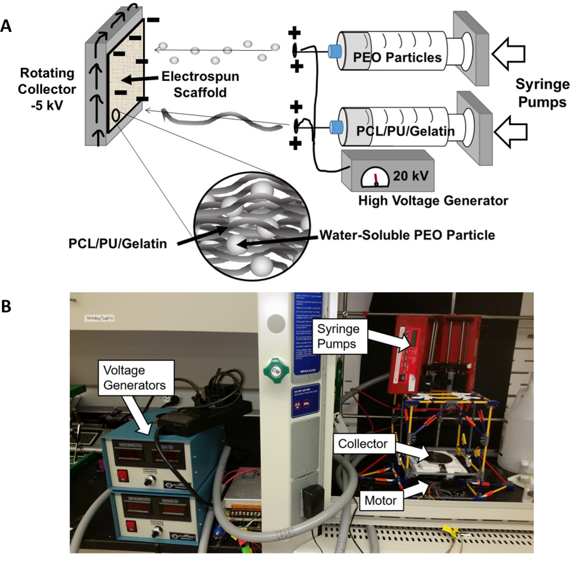
Custom Rotating Co-Electrospinning Apparatus Setup. A) Schematic of electrospinning setup showing deposition of PEO particles and PCL/PU/Gelatin fibers. B) Photograph of co-electrospinning setup used for this work. PEO and PCL:PU:Gelatin solutions were extruded through a positively charged syringe (20 kV) and collected on a negatively charged rotating collector (−5 kV).
The PEO and PU:PCL:Gelatin solutions were placed in separate 10 mL syringes and fitted into two programmable syringe pumps (NE-300, New Era Syringe Pumps, Farmingdale, NY) set to extrude at 5 mL/hr for the PU/PCL/Gelatin blend or 7 mL/hr for the PEO solution. As the solutions were extruded through a charged 20 gauge needle (+20 kV; Gamma High Voltage, Ormond Beach, FL), the charged polymers were drawn a distance of 14 cm from the needle tips to a negatively charged (−5 kV) copper plate (10 cm diameter) rotating horizontally at 60 rpm. Each PU:PCL:Gelatin polymer blend was electrospun for 60 minutes with and without PEO. This process was repeated two more times to achieve 3 electrospun sheets of each blend with and without PEO. Mats were vented overnight in the fume hood to remove residual HFIP/chloroform.
Scaffolds were cut with 6 mm, 10 mm, or 12 mm diameter biopsy punches at a distance of 1–3 cm from the edge of each electrospun sheet. The PEO was washed out of the scaffolds in DI water for 4 hours with one DI water exchange at 2 hours. The scaffolds were then frozen and lyophilized for 2 days.
2.3. PEO Content, Porosity, and Volume Change
To determine the PEO content of the scaffolds, the dry weights of 10 mm scaffolds were weighed before and after rinsing (n=6). The PEO content was determined as the percent difference in weight from before and after rinsing.
Scaffold porosity was determined using the gravimetric method. The mass of the sample was measured, followed by the outside diameter, thickness, and height (calipers ± 0.01 mm, n=3). The individual bulk densities of PCL, PU, and gelatin were 1.125 g/mL, 1.2 g/mL, and 1.33 g/mL, respectively, and these values were used to calculate weighted bulk densities (ρ) for each of the different PCL:PU:Gelatin blends. Using this information, the apparent density and porosity were calculated according to the equation: ρapp= m / (πr2t), porosity (%) = (1-ρapp/ρ) × 100, with m, r, t, and ρ as the mass, radius, thickness, and weighted bulk density, respectively.
The volume change was assessed by measuring outside diameter, thickness, and height on dry scaffolds both before and after rinsing, where the volume change was calculated as the difference in volume divided by the original volume (i.e., the volume before rinsing).
2.4. Scanning electron microscopy (SEM), Fiber Diameter Measurement, and Pore Size
Scaffolds from all PCL:PU:Gelatin blends both before and after rinsing were lyophilized for 2 days prior to SEM imaging. Scaffolds were affixed to SEM sample stubs and sputter coated for 30 seconds using a gold/palladium target (Leica EM ACE200). SEM imaging was performed at 10 kV using a JEOL JSM-6010LA SEM.
Fiber diameters for all PCL:PU:Gelatin blends were assessed using Diameter J in Image J.17 Each greyscale SEM image was segmented using the DiameterJ traditional segmentation algorithm to produce eight 8-bit black and white segmentations per SEM image. The best segmentation of the eight was selected based on the following criteria: (1) no partial fiber segmentations, (2) the intersections of fibers do not contain black spots (i.e. holes), (3) segmented fibers are representative of actual fibers in the image and are not background/imaging artifacts, and (4) segmentations accurately represent fibers’ actual diameter (representative image in Supplementary Fig. 1). The selected segmentations were scaled and processed in DiameterJ to quantify fiber characteristics.
Pore size for all PCL:PU:Gelatin blends were also measured using ImageJ analysis. Grayscale images from 5 samples of each blend (n=5) were used to measure pore size. After softening the image to reduce noise, the threshold was adjusted to 20% to produce black and white images of the pores. Particle analysis was then used to measure the size of all pores above 0.1 μm2.
2.5. Mechanical Testing
Tensile tests were performed using a dynamic mechanical analyzer (Q800 TA Instruments, New Castle, DE). Before testing, each specimen was hydrated in PBS overnight. Specimen dimensions were measured using calipers (± 0.01 mm). After securing samples between the tensile grips, a tensile load was applied at 0.1 mm/s until sample failure (n=3). Stress-strain curves were generated and ultimate tensile strength (UTS) was determined as the maximum stress before sample failure and the Young’s Modulus was calculated as the slope of the linear portion of the stress-strain curve (representative curves shown in Supplementary Fig. 2).
2.6. Cell Culture and Seeding for In Vitro Cell Infiltration Analysis
Normal human dermal fibroblasts (nhDF; CC-2511, Lonza, Walkersville, MD) were passaged until P4 in high-glucose DMEM (Corning), 10% FBS (Life Technologies), 1% GlutaMax (Life Technologies), and 1% Penicillin/Streptomycin (Corning). Prior to seeding with cells, the scaffolds (6mm diameter, n=5) were submerged in 100% ethanol for 30 minutes and were then dried in a cell culture hood. The scaffolds were placed in a 48 well plate (Greiner Bio-One) inside the cell culture hood and were then subjected to UV light for 15 minutes on each side. Each scaffold was then seeded with 10 μl media containing 10,000 cells. Extra media (not to exceed 10 μl) was added to any scaffold that was not fully wettened by media. These seeded scaffolds were placed in the incubator for 1.5 hours and then 350 μl media was added to each well. The media was exchanged every other day for 2 weeks.
2.7. Scaffold Preparation for In Vivo Experiments
Scaffolds (6mm diameter, n=5 per group) were sterilized as described above and placed in individual wells of a 48-well plate. After sterilization, scaffolds were loaded with PEGylated fibrin gel. Briefly, human fibrinogen (Millipore Sigma, 341576) was dissolved in sterile PBS at a concentration of 40 mg/mL. Homobifunctionalized n-hydroxysuccinimydel poly(ethylene glycol) (3.4 kDa, SUNBRIGHT DE-034HS, NOF America Corporation) was dissolved in sterile PBS at a concentration of 4 mg/mL. After complete dissolution, the fibrinogen and PEG solutions were mixed at a 1:1 volume ratio and allowed to react for 1 hour at 37C. Human thrombin (Millipore Sigma, 605190) was dissolved in a solution of 145 mM NaCl and 20 mM CaCl2 at a concentration of 2 units/mL. 20 μl of the PEGylated fibrinogen solution was added to the top of each scaffold. Immediately after, 20 μl of the thrombin solution was added. After 10 minutes at 37C, the wells were filled with PBS and the scaffolds allowed to fully hydrate overnight at 37C.
2.8. Subcutaneous Mouse Implantation
To assess the immune response and cell infiltration of the polymer blends with differing porosity, scaffolds were implanted into athymic nude mice (6–7 weeks old, Foxn1nu; Envigo) in a protocol approved by the Institutional Animal Care and Use Committees at the University of Colorado Anschutz Medical Campus (IACUC protocol #00564). Mice were anesthetized with isoflurane and two scaffolds were implanted into each mouse in opposite dorsal, posterior pockets. After 7 days, mice were sacrificed and scaffolds were explanted while retaining the surrounding tissue.
2.9. Histology and Quantification
Samples from in vitro studies (n=5) were rinsed with PBS, fixed in formalin for 48h, and sent to the Biorepository Core Facility at the University of Colorado Anschutz Medical Campus for paraffin embedding, sectioning, and H&E staining. To analyze cell infiltration in the in vitro samples, three random brightfield images at 20X were taken from each H&E-stained sample on an Axio Observer Z1 Microscope (Carl Zeiss Microscopy, Jena, Germany). The depth of every cell in each image for all 3 images per sample were recorded.
Sample from in vivo studies (n=4–7) were similarly stained with H&E, as well as immunofluorescent staining with DAPI, an anti-CD68 antibody, and an anti-CD206 antibody. CD68 and CD206 staining was used to qualitatively analyze macrophage presence and polarization. The DAPI-stained sections were used to quantify cell density within the scaffold, cell infiltration distance, and cell density directly surrounding the scaffold to measure the immune system-mediated capsule formation. Cell quantification for the in vivo sections was performed using a MATLAB program. The program utilizes Otsu’s Thresholding and a watershed process to identify and segment cell nuclei from the DAPI channel. Following nuclei segmentation, the program measured the minimum distance of each nuclei from a user-defined boundary drawn along the scaffold edge. This allowed measurement of cell infiltration depth, as well as cell density within a border region, which was utilized to estimate encapsulation by also measuring cell density within 30 μm of the drawn border.
2.10. Statistical Analysis
All statistics were performed on GraphPad Prism 6 statistical software (GraphPad Software, Inc., La Jolla, CA). Where applicable, a two-factor ANOVA was used followed by a Tukey’s post hoc test, where p ≤ 0.05 was considered significant. Quantitative results are reported as mean ± standard deviation within the text and as mean + standard deviation within the figures.
3.0. RESULTS
3.1. Increasing PCL content reduces pore collapse after removal of sacrificial PEO particles
Incorporation of PEO in the scaffolds was confirmed by measuring the scaffold dry weights before and after rinsing with water (Fig. 2A). All groups containing PEO had significant reductions in volume after rinsing the scaffolds to remove the PEO (Fig. 2B). The volume change varied from 25.6% reduction in volume for the 0% PU + PEO group (PCL only) up to a 75.9% reduction in volume for the 75% PU + PEO group (PU only) (p<0.05). These results indicate that increasing the PCL concentration of the blended polymer decreases the scaffold shrinkage that occurs after removal of the sacrificial particles.
Figure 2:
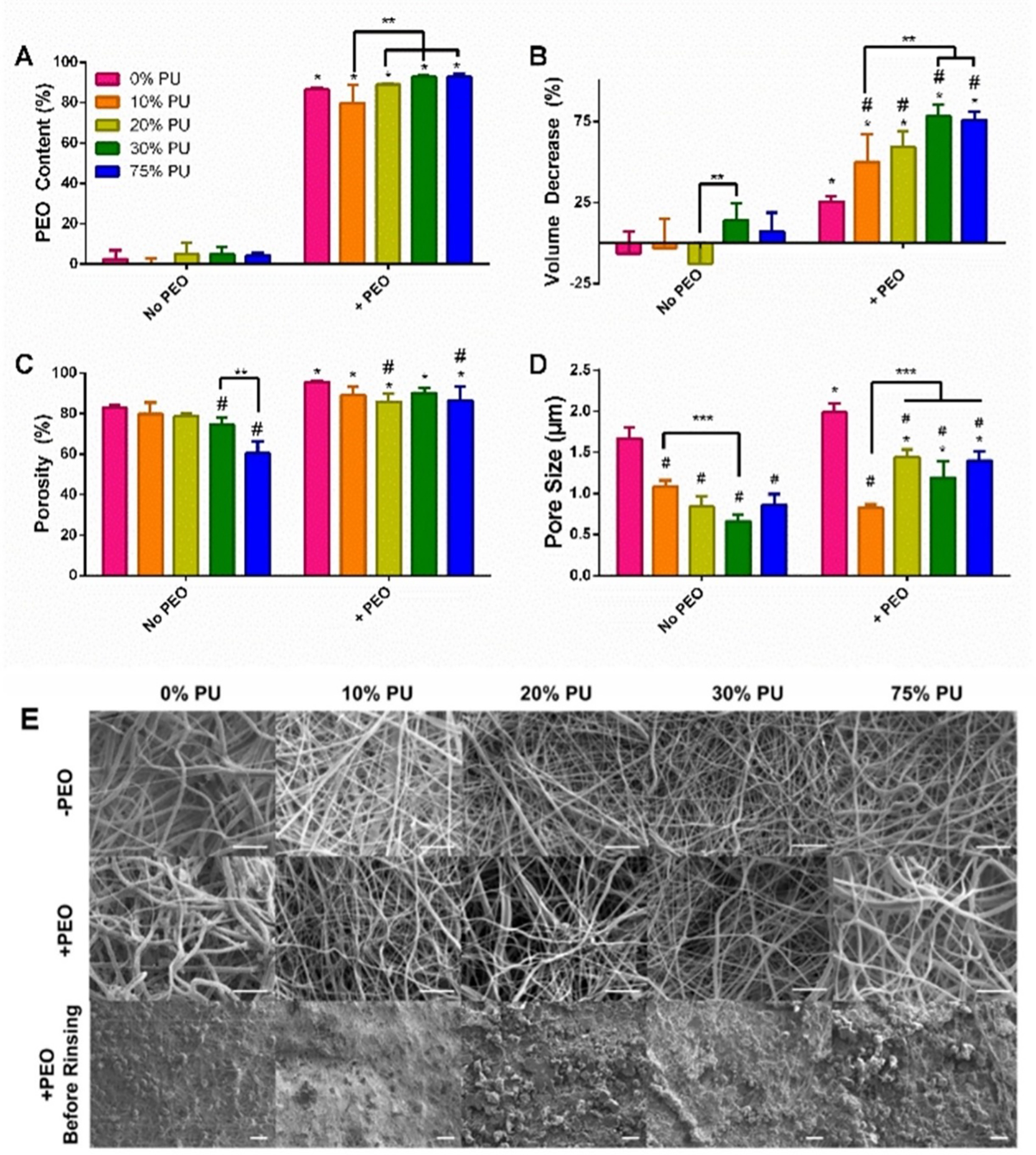
Acellular Analysis of PCL:PU:Gelatin Blends. A) PEO Content of Scaffolds. The PEO content of the scaffolds containing PEO ranged from 80–90%. B) Volume Change of Scaffolds. Increasing PU caused significant shrinkage of the scaffolds. C) Porosity of Scaffolds. PEO incorporation significantly increased the porosity of all blends. D) Pore Size. The 0% PU group had the largest pore size increase with PEO incorporation, but all groups had an increase in pore size, whether or not it was significant. Data are mean + SD. *Significantly different from same group without PEO. #Significantly different from 0% PU group at same PEO content. **p<0.05. E) SEM Images of all blends with and without PEO as well as of the scaffolds prior to rinsing the PEO particles. The scaffolds containing rinsed PEO show larger spacing between fibers. Scale bar for top two rows = 10 μm. Scale bar for bottom row = 100 μm.
3.2. Sacrificial PEO particles increase scaffold porosity and pore size
PEO incorporation significantly increased the porosity for all groups (p<0.05; Fig. 2C). Specifically, the porosity for the 0%, 10%, 20%, 30%, and 75% PU minus PEO groups increased by 15.2%, 11.7%, 9.0%, 20.9%, and 43.5%, respectively, with the incorporation of PEO (p<0.05). In the absence of PEO, the 30% and 75% PU groups were 10.1% and 27.2% less porous than the 0% PU group (p<0.05). Finally, the 20% and 75% PU + PEO groups had a 10.1% and 9.3% reduction in porosity, respectively, compared to that of the 0% PU + PEO group (p<0.05) (Fig. 2C).
SEM imaging of scaffolds with and without PEO revealed that the scaffolds containing rinsed PEO show larger spacing between fibers versus the groups without PEO, indicated by the increased contrast in the images of the plus PEO groups (Fig. 2E). Furthermore, the SEM images reveal the presence of PEO particles prior to rinsing (Fig. 2E). Quantitative analysis of pore size revealed significant differences between groups with and without PEO (Fig. 2D). All PCL:PU:Gelatin blends that included PEO had significantly larger pores than their non-PEO counterparts (p<0.05), except for the 10% PU blend which was not significantly different. Additionally, the 0% PU blend with and without PEO demonstrated significantly higher pore size compared to any of the other blends within their respective PEO grouping (p<0.05).
3.3. Increasing PU and inclusion of PEO both decreased scaffold Young’s modulus without compromising tensile strength
Increasing PU in the patches without PEO decreased the bulk Young’s modulus from 33.0 MPa for PCL-only patches to 3.8 MPa for PU-only patches (Fig. 3A). The addition of PEO further reduced the Young’s modulus for each corresponding polymer blend. Perhaps most notably, the addition of PEO reduced the Young’s modulus of the PCL-only patch by 68% to 10.5 MPa, causing it to be statistically identical to the moduli of each polymer blend except for the PU-only patch (reduced by 68% to 0.7 MPa). The tensile strength of every material type, regardless of PEO content or PU/PCL ratio, greatly exceeded the requirement of at least 200 kPa, which is necessary to withstand suturing and the mechanical demands on the heart wall.
Figure 3:
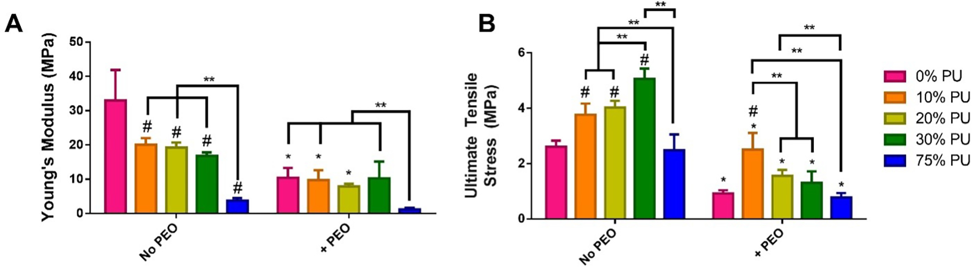
Mechanical testing of scaffolds. A) Young’s modulus of each scaffold was calculated from the slope of the linear region of the stress-strain curve generated during longitudinal tensile testing. B) Ultimate tensile strength was calculated as the breaking point during longitudinal tensile testing.
3.4. Addition of PU reduces cell infiltration in vitro
After seeding with hDFs and culturing for 2 weeks, H&E stains were performed to visualize the depth of cell infiltration of the different PU blends with and without PEO incorporation. The greatest cell infiltration was observed in the 0% PU groups with and without PEO. This is consistent with our pore size analysis as well, which determined the 0% PU groups had the greatest pore sizes. Minimal cell infiltration was observed in the 10–75% PU minus PEO scaffolds. Including PEO was observed to improve cell infiltration in all PU-containing groups; however, there were no significant differences within the PU-containing groups. Increasing the proportion of PCL in the polymer blends did not improve cell infiltration (Fig. 4A). The addition of PEO did not significantly increase cell infiltration in the scaffolds made of 0–10% PU (Fig. 4B). There was an increase in cell infiltration for the 20–75% PU groups with the incorporation of PEO; however, the only significant increase was observed in the 20% PU + PEO group (p<0.0001) (Fig. 4B). Therefore, this group was chosen as the polymer blend to be included in the in vivo experiments.
Figure 4:
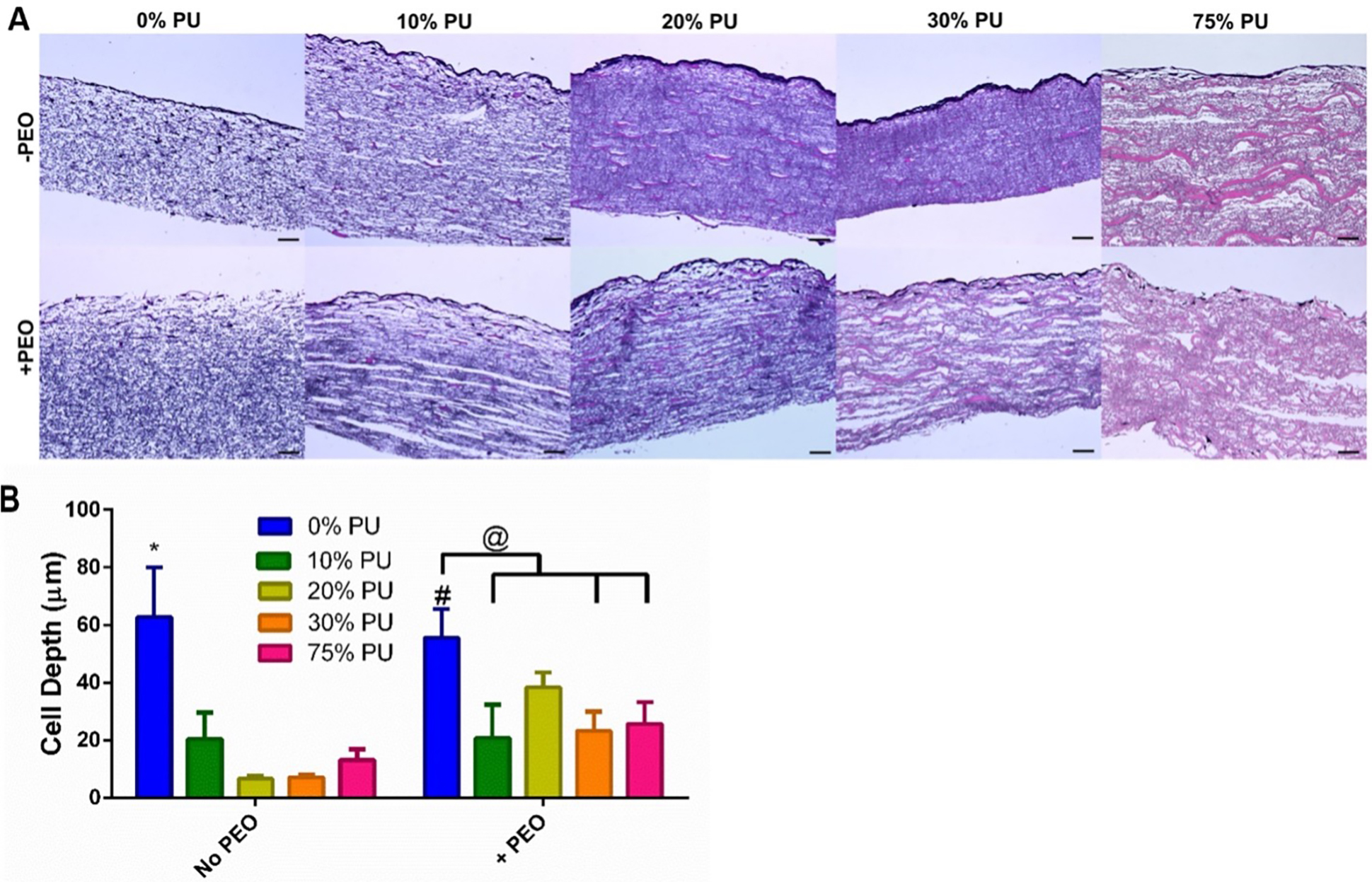
Cellular Infiltration of hDFs in vitro. A) H&E Stains of scaffolds after 2 weeks of culture with hDFs. An increase in cell depth was observed for 20–75% PU + PEO scaffolds in comparison to the same scaffolds without PEO. Scale bars are 50 μm. B) Quantification of cell depth infiltration for each scaffold (n=5). PEO significantly increased cellular depth for the 20% PU group, but none of the others. However, the incorporation of PEO did tend to increase cell depth tended to increase for 20%–75% PU groups. Data are mean ± SD. *Significantly different from all other groups within same PEO content. #Significantly different from same group without PEO. @p<0.05.
3.5. Increasing PU content decreases infiltrated cell density of scaffolds in vivo
Following 7 days of subcutaneous implantation in nude mice, the tested PCL:PU:Gelatin blends with and without PEO demonstrated varying degrees of cellular infiltration and inflammatory response (Fig. 5 and 6A). H&E staining of the scaffolds demonstrated all patches were still intact after the implant period (Fig. 5). Quantification of cell infiltration by the MATLAB program (Fig. 6D) revealed that blends with an increased PCL content had a significantly increased cell infiltration, both with and without PEO (Fig. 6A). These results are consistent with our in vitro cell infiltration experiments that also showed increased infiltration depth in the 0% PU group. However, immunohistochemical staining of the in vivo scaffolds revealed many of the infiltrated cells were CD68+, suggesting they are primarily macrophages. The lack of CD206 staining also indicates these cells are not demonstrating an anti-inflammatory activation.
Figure 5:
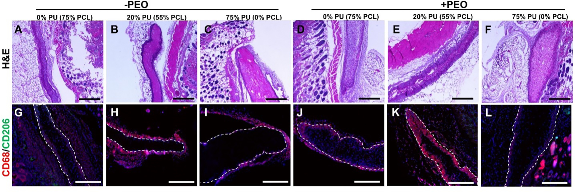
Histology of Explanted Scaffolds. A-F) H&E stains of scaffolds. Clear encapsulation can be observed in the 20% PU blend (numerous dark nuclei surrounding patch in B and E), while strong cellular infiltration is observed in the PCL scaffolds (A and D). G-L) CD68 (pan-macrophage marker) and CD206 (M2 macrophage marker) IF staining of scaffolds. Very few M2 macrophages were detected. Strong macrophage response to 20% PU blend (H and K), while PU scaffolds exhibit almost no macrophage response (I and L). All scale bars 500 μm.
Figure 6:
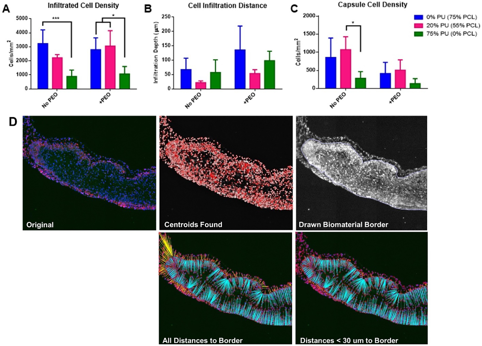
Quantification of Explanted Scaffolds. A) Average density of cells infiltrated into the scaffolds 1 week after implant. B) Infiltration distance from edges of scaffolds. C) Density of cells within 30 μm of scaffold edges, indicating level of immune-regulated encapsulation. D) 5 stages of histological quantification. Starting with the original stained section, MATLAB was used to identify all cells, draw the scaffold border, then count the infiltrated cells and measure their distances of from the border. *p<0.05, ***p<0.001.
3.6. Addition of PEO increases cell infiltration depth and decreases scaffold encapsulation in vivo
The inclusion of PEO in the scaffolds for the in vivo implants did not lead to significant differences in the cell infiltration density, but it did seem to affect the cell infiltration distance and encapsulation compared to groups without PEO (Figs. 5, 6B, 6C). While not significantly different, all groups at 0%, 20%, and 75% PU containing PEO demonstrated increased cell infiltration depth compared to their respective counterparts without PEO (Fig. 6B). Interestingly, the polymer blend containing both PU and PCL (20% PU, 55% PCL) had the lowest cell infiltration depth, both with and without PEO. Again, these results are not statistically significant.
Groups with PEO also demonstrated decreased encapsulation around the implant, as quantified by a decreased cell density within 30 μm of the exterior of the drawn border (Fig. 6C). All polymer blend groups containing PEO demonstrated decreased capsule cell density compared to their respective counterparts without PEO, though again these results are not statistically significant. The 20% PU group also demonstrated the highest capsule cell density within each PEO grouping, and the capsule cell density in the 20% PU blend without PEO was significantly greater than the 75% PU blend without PEO (Fig. 6C)
4.0. DISCUSSION
Congenital heart defects are the leading cause of death among live-born infants.1,2 Tissue engineered patches that can be used by pediatric surgeons to correct these defects are desperately needed because current patch materials are inert, non-degradable, and do not grow with the patient. In preliminary experiments, we fabricated electrospun PCL and PU scaffolds with and without sacrificial PEO particles for this purpose. However, we discovered that the pores in PU scaffolds collapse after removal of the sacrificial PEO particles, preventing any cell infiltration. We also found that the PCL scaffolds were much stiffer than the PU scaffolds and hypothesized that the PCL scaffolds would trigger an undesirable inflammatory response. Therefore, in this study, we sought to create a scaffold that exhibited the high cell infiltration properties of PCL while preserving the lower stiffness and decreased inflammatory response of PU. We fabricated five PU-PCL polymer blends (0, 10, 20, 30, and 75% PU, corresponding to 75, 65, 55, 45, and 0% PCL; all scaffolds contained 25% gelatin) with and without sacrificial PEO (a total of 10 scaffold types) and assessed the scaffold mechanics, porosity, cell infiltration in vitro and in vivo, and immune response in vivo.
In seeking to prevent pore collapse during PEO removal, we found that decreasing the content of PU (increasing the PCL content) in the scaffolds resulted in greater pore preservation (less decrease in volume after rinsing), as expected (Fig. 2B). However, it remained that the PCL-only scaffold retained its pores after PEO rinsing significantly better than any PU-containing scaffold.
Also as expected, we found that as PU content increased, scaffold stiffness decreased. However, even though the PU-PCL blends were less stiff than the PCL-only scaffold, the PU-only scaffold remained significantly less stiff than any of the other scaffolds (Fig. 3A). Interestingly, the addition of PEO removed any significant difference in stiffness between the PCL-only scaffold and any of the polymer blends, although the PU-only scaffold remained significantly less stiff. It is worth noting that even the PU-only scaffold with PEO, while certainly the less stiff, remains two orders of magnitude stiffer than native heart muscle (~700 kPa for PU plus PEO scaffolds versus ~10 kPa for native heart tissue). Therefore, the decrease in Young’s modulus between PCL and PU may be irrelevant in constructing a cardiac patch with these materials. All 10 scaffold types exhibited sufficient tensile strength for suturing into the heart and withstanding its mechanical forces.
After seeding cells onto the surfaces of the scaffold types in vitro and measuring cell infiltration, we discovered that the PU-PCL blends did not significantly improve cell infiltration compared to PU-only (Fig. 4B). The addition of PEO appears to have improved cell infiltration slightly in PU-containing scaffolds, but this trend is not statistically significant.
In the final experiment, scaffolds were implanted subcutaneously into the backs of mice. 7 day readouts included macrophage response, cell infiltration, and cell encapsulation. For this experiment, PCL-only, 20% PU, and PU-only (+/− PEO) were selected, resulting in the analysis of six scaffold types. As hypothesized, the PCL-only group with and without PEO displayed a higher inflammatory response (macrophage presence and cell encapsulation) than the PU-only group (Fig. 5 and 6C). Unexpectedly, the 20% PU group displayed the highest inflammatory response of all the groups, regardless of PEO content. Furthermore, the 20% PU group allowed the least cell infiltration distance (Fig. 6B). As expected, the inclusion of PEO allowed for greater cell infiltration distance in all material types and it also reduced cell encapsulation in all groups, but the trends between material types remained the same (Fig. 6B). These results confirm that PCL plus PEO scaffolds allow for the most cell infiltration while PU plus PEO scaffolds exhibit the least inflammatory response and lowest stiffness. We hypothesized that blends of PU and PCL would be able to recapitulate both of these characteristics; however, none of the PU-PCL polymer blends fully obtained any of these desirable properties. There was no significant difference between blends and PCL-only in Young’s modulus, pore preservation after PEO washing remained significantly worse in all blends than PCL-only, cell infiltration was not significantly improved in blends compared to PU-only, and the inflammatory response of the most promising blend (20% PU) was more severe than both of the pure polymer scaffolds.
Therefore, the discussion surrounding the most promising scaffold for heart tissue engineering moves to the choice between PCL-only and PU-only scaffolds, both containing PEO sacrificial particles. To answer this question, we look towards the three primary properties of interest (scaffold mechanics, cell infiltration, and inflammatory response) and discuss how much each property matters in cardiac tissue engineering as well as how significant the measured differences are between the scaffold types. First, with regard to scaffold mechanics, we found that both PU and PCL scaffolds retain sufficient tensile strength to be used to repair full wall-thickness heart defects. However, an increased Young’s modulus in implanted materials and in the native heart itself has been shown to increase fibrosis, prevent cardiomyocyte proliferation, and drive pathogenic heart remodeling.18–20 PU plus PEO scaffolds are significantly less stiff than their PCL counterparts, however neither scaffold comes close to physiologic values. We expect, therefore, that the two scaffolds would perform similarly in situ. Second, with regard to cell infiltration, we see clearly that PCL plus PEO scaffolds allow for significantly more cell infiltration than their PU counterparts in vitro and in vivo, but the importance of cell infiltration in cardiac patches is an open question. If the scaffolds were to be seeded with cells prior to implant in situ, the ability of the cells to infiltrate is likely important for cell retention and viability. However, both PU and PCL allow for cell adhesion on all surfaces, so it is possible that infiltration into the biodegradable scaffold is not important so long as heart tissue can grow on the surface prior to scaffold degradation. Finally, while the PCL scaffolds drove an increased inflammatory response compared to the PU scaffolds, it remains to be seen whether this inflammatory response is harmful or beneficial in the heart. Increasing evidence is demonstrating the importance of an initial immune response in tissue regeneration.21,22 Since our subcutaneous mouse study only lasted for 7 days and the scaffolds were not implanted into the heart, this potential benefit of the initial immune response in long-term healing is impossible to resolve.
Assessing both scaffold types (PU plus PEO and PCL plus PEO) in situ in a heart wall replacement model would be the best way to assess the differences between these two material types. Implanting scaffolds with and without seeded cells would illuminate the importance of cell infiltration for implanted cell viability and retention. Early (e.g., 1 week), middle (e.g., 2–4 week) and late (e.g., 12 week) timepoints would allow for elucidation of the changing immune/inflammatory response and stages of tissue regeneration.
5.0. CONCLUSIONS
In this work, we have shown that we can fabricate electrospun scaffolds with high porosity using blends of PU, PCL, and sacrificial PEO particles. The inclusion of PEO in all scaffold types decreased scaffold stiffness, increased pore size and cell infiltration, and reduced the inflammatory response in vivo. Decreasing ratios of PU (increasing PCL) in the scaffolds resulted in improved pore retention after rinsing of sacrificial particles and increasing scaffold stiffness, but no significant improvements in cell infiltration compared to PU alone. Within the goal of creating scaffolds for the repair of congenital heart defects, we conclude that PCL plus PEO scaffolds are the most promising because of their promotion of cell infiltration, however the increased inflammatory response that PCL scaffolds elicit compared to PU may prove to be harmful to tissue regeneration. Future efforts will assess both material types in situ in a rat myocardial wall replacement model to answer these questions.
Supplementary Material
Supplementary Figure 1: Representative SEM analysis for fiber diameter and pore size. DiameterJ used to segment SEM images into black and white representations of fibers. Outputs included histogram of fiber and pore sizes.
Supplementary Figure 2: Representative stress-strain curves for 20% PU with and without PEO. Young’s modulus calculated as slope of linear region between 0 and 100% strain. Ultimate tensile strength calculated as stress at failure.
6.0. ACKNOWLEDGMENTS
We gratefully acknowledge an NIH T32 training grant for the support of E.C.B., an NIH F31 predoctoral fellowship for the support of D.K.J., an AHA postdoctoral fellowship for the support of M.C.V., and an NIH R01 awarded to J.G.J. We also would like to thank Eric Wartchow and the Electron Microscopy Laboratory at Children’s Hospital Colorado for their assistance with SEM imaging. Additionally, we would like to acknowledge Sean Glaister for designing and building the electrospinning collector system that was used in this project. Finally, we appreciate the help of the Gates Center for Regenerative Medicine Morphology and Phenotyping Core for their assistance with histology.
Footnotes
CONFLICT OF INTEREST
The authors declare no conflicts of interest.
8.0 REFERENCES
- 1.Miranovic V The incidence of congenital heart disease: previous findings and perspectives. Srp Arh Celok Lek 142, 243–248, doi: 10.2298/sarh1404243m (2014). [DOI] [PubMed] [Google Scholar]
- 2.Wu W, He J & Shao X Incidence and mortality trend of congenital heart disease at the global, regional, and national level, 1990–2017. Medicine (Baltimore) 99, e20593, doi: 10.1097/MD.0000000000020593 (2020). [DOI] [PMC free article] [PubMed] [Google Scholar]
- 3.Kalfa D, Bel A, Chen-Tournoux A et al. A polydioxanone electrospun valved patch to replace the right ventricular outflow tract in a growing lamb model. Biomaterials 31, 4056–4063 (2010). [DOI] [PubMed] [Google Scholar]
- 4.Klouda L, Tsao C & Jacot JG Tissue Engineering in Congenital Heart Disease.
- 5.Prabhakaran MP, Kai D, Ghasemi-Mobarakeh L et al. Electrospun biocomposite nanofibrous patch for cardiac tissue engineering. Biomedical Materials 6, 055001 (2011). [DOI] [PubMed] [Google Scholar]
- 6.Wang K, Xu M, Zhu M et al. Creation of macropores in electrospun silk fibroin scaffolds using sacrificial PEO-microparticles to enhance cellular infiltration. Journal of Biomedical Materials Research Part A 101, 3474–3481 (2013). [DOI] [PubMed] [Google Scholar]
- 7.Voorneveld J, Oosthuysen A, Franz T et al. Dual electrospinning with sacrificial fibers for engineered porosity and enhancement of tissue ingrowth. Journal of Biomedical Materials Research Part B: Applied Biomaterials (2016). [DOI] [PubMed] [Google Scholar]
- 8.Baker BM, Gee AO, Metter RB et al. The potential to improve cell infiltration in composite fiber-aligned electrospun scaffolds by the selective removal of sacrificial fibers. Biomaterials 29, 2348–2358 (2008). [DOI] [PMC free article] [PubMed] [Google Scholar]
- 9.Lavielle N, Hébraud A, Schlatter G et al. Simultaneous electrospinning and electrospraying: a straightforward approach for fabricating hierarchically structured composite membranes. ACS applied materials & interfaces 5, 10090–10097 (2013). [DOI] [PubMed] [Google Scholar]
- 10.Hodge J & Quint C The improvement of cell infiltration in an electrospun scaffold with multiple synthetic biodegradable polymers using sacrificial PEO microparticles. J Biomed Mater Res A 107, 1954–1964, doi: 10.1002/jbm.a.36706 (2019). [DOI] [PMC free article] [PubMed] [Google Scholar]
- 11.Radisic M & Christman KL in Mayo Clinic Proceedings. 884–898 (Elsevier; ). [DOI] [PMC free article] [PubMed] [Google Scholar]
- 12.Pok S, Myers JD, Madihally SV et al. A multilayered scaffold of a chitosan and gelatin hydrogel supported by a PCL core for cardiac tissue engineering. Acta biomaterialia 9, 5630–5642 (2013). [DOI] [PMC free article] [PubMed] [Google Scholar]
- 13.Isaka M, Nishibe T, Okuda Y et al. Experimental study on stability of a high-porosity expanded polytetrafluoroethylene graft in dogs. Ann Thorac Cardiovasc Surg 12, 37–41 (2006). [PubMed] [Google Scholar]
- 14.Sacks MS & Chuong CJ Orthotropic mechanical properties of chemically treated bovine pericardium. Ann Biomed Eng 26, 892–902, doi: 10.1114/1.135 (1998). [DOI] [PubMed] [Google Scholar]
- 15.Tremblay D, Zigras T, Cartier R et al. A comparison of mechanical properties of materials used in aortic arch reconstruction. Ann Thorac Surg 88, 1484–1491, doi: 10.1016/j.athoracsur.2009.07.023 (2009). [DOI] [PubMed] [Google Scholar]
- 16.Guan J, Sacks MS, Beckman EJ et al. Synthesis, characterization, and cytocompatibility of elastomeric, biodegradable poly (ester-urethane) ureas based on poly (caprolactone) and putrescine. Journal of biomedical materials research 61, 493–503 (2002). [DOI] [PubMed] [Google Scholar]
- 17.Hotaling NA, Bharti K, Kriel H et al. DiameterJ: A validated open source nanofiber diameter measurement tool. Biomaterials 61, 327–338, doi: 10.1016/j.biomaterials.2015.05.015 (2015). [DOI] [PMC free article] [PubMed] [Google Scholar]
- 18.Haack T & Abdelilah-Seyfried S The force within: endocardial development, mechanotransduction and signalling during cardiac morphogenesis. Development 143, 373–386, doi: 10.1242/dev.131425 (2016). [DOI] [PubMed] [Google Scholar]
- 19.Jacot JG, McCulloch AD & Omens JH Substrate stiffness affects the functional maturation of neonatal rat ventricular myocytes. Biophys J 95, 3479–3487, doi: 10.1529/biophysj.107.124545 (2008). [DOI] [PMC free article] [PubMed] [Google Scholar]
- 20.Notari M, Ventura-Rubio A, Bedford-Guaus SJ et al. The local microenvironment limits the regenerative potential of the mouse neonatal heart. Sci Adv 4, eaao5553, doi: 10.1126/sciadv.aao5553 (2018). [DOI] [PMC free article] [PubMed] [Google Scholar]
- 21.Ben-Mordechai T, Holbova R, Landa-Rouben N et al. Macrophage subpopulations are essential for infarct repair with and without stem cell therapy. J Am Coll Cardiol 62, 1890–1901, doi: 10.1016/j.jacc.2013.07.057 (2013). [DOI] [PubMed] [Google Scholar]
- 22.Vagnozzi RJ, Maillet M, Sargent MA et al. An acute immune response underlies the benefit of cardiac stem cell therapy. Nature 577, 405–409, doi: 10.1038/s41586-019-1802-2 (2020). [DOI] [PMC free article] [PubMed] [Google Scholar]
Associated Data
This section collects any data citations, data availability statements, or supplementary materials included in this article.
Supplementary Materials
Supplementary Figure 1: Representative SEM analysis for fiber diameter and pore size. DiameterJ used to segment SEM images into black and white representations of fibers. Outputs included histogram of fiber and pore sizes.
Supplementary Figure 2: Representative stress-strain curves for 20% PU with and without PEO. Young’s modulus calculated as slope of linear region between 0 and 100% strain. Ultimate tensile strength calculated as stress at failure.