Abstract
Biomass materials, an important source of chemical feedstocks, could replace fossil fuels as a resource in the future. The chemical feedstocks from biomass materials are used in many medical and pharmaceutical products and in fuels, chemicals, and functional materials. Biomass materials are expected to be used in biomedical engineering fields, especially due to their low biotoxicity. By the way, most of the demand for bio-application fields is an application targeted for customized production, so a high formability is required for production. Research on three-dimensional (3D) printing technology capable of satisfying these requirements has been ongoing. Manufacturing additives need to be investigated to use biomass materials as a resin or bioink safely for 3D printing, which is a technique widely used in biomedical engineering fields. In this study, a projection microstereolithography (PμSL) system, a 3D printing technique, was made that uses a biomass-based resin. Biomass materials are designed to be photocurable for use in the PμSL process. Various PμSL process parameters were investigated using the biomass-based resin to determine the optimum fabrication conditions for 3D structures. This study demonstrated that a biomass-based resin can be used in the PμSL process. We provide a method for its application in various biomedical engineering fields.
Keywords: biomass-based resin, three-dimension geometry fabrication, projection microstereolithography, process conditions, process optimization
Introduction
Additive manufacturing technology simplifies the manufacturing process and reduces the processing time compared with conventional manufacturing techniques. Three-dimensional (3D) printing technology and different additive manufacturing techniques have been studied for the past few decades. According to the American Society for Testing and Materials (ASTM) International Standard Organization, 3D printing technology is classified into the following seven categories1–3: vat photopolymerization,4–7 material jetting,8 binder jetting,9,10 material extrusion,11,12 powder bed fusion,13,14 sheet lamination,15 and directed energy deposition.16,17
Among these, vat photopolymerization is an additive manufacturing process in which a liquid resin in the vat is selectively cured by photoactive polymerization.18 In the vat photopolymerization category, the projection microstereolithography (PμSL) method19,20 is widely used in biomedical engineering research21 because of its rapid production speed and microstructure production compared with the stereolithography apparatus (SLA) method.22,23 The PμSL method uses ultraviolet (UV) lamps that cure the entire cross section of a structure at once. Therefore, the PμSL method is advantageous in production speed compared with the SLA, a scanning method. In addition, unlike typical lithography methods that expose UV light from a photomask, PμSL is a maskless lithography system based on a digital mirror device (DMD).24 The DMD controls the on/off state of the UV light according to the two-dimensional data of each layer, eventually creating a single-layer pattern. The precision of PμSL is based on the resolution of the exposed light, and it enables precise manufacturing of fine structures compared with other processes.25
However, because most photocurable resins used for fabrication have a biotoxicity, there is a possibility of mutations occurring in cells when used in biomedical engineering fields. Consequently, this has hindered the clinical application of PμSL.26 Biomass materials, an important source of chemical feedstocks, could replace fossil fuels as a resource in the future. They are expected to be used in biomedical engineering fields due to their low biotoxicity.27 These biomass materials are currently used as alternative sources of feedstock chemicals to produce plastics, films, coatings, and adhesives. However, there are not many studies on biomass materials used in additive manufacturing, in other words, 3D printing.
In this article, the PμSL process was selected to produce 3D microstructures with a biomass-based resin. A PμSL system was built with a DMD chip and a UV light-emitting diode (LED). A UV curable biomass-based resin was designed and produced. The process conditions for fabricating 3D microstructures were investigated and optimized for the PμSL and biomass-based resin. The UV curing conditions of the build plate and the curing conditions between the resins were evaluated to understand the PμSL process with the biomass-based resin. The widths and thicknesses of the cured patterns were evaluated according to the UV light exposure time to create a basis for the production of 3D shapes according to the desired design conditions. This study shows that biomass materials can be used to make biomass-based resins, which can be used to produce 3D microstructures for future biomedical engineering applications.
Experimental Setup
Biomass-based resin
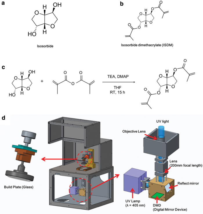
Biomasses, eco-friendly bioplastic materials, are made from renewable or sustainable resources such as corn, sugarcane, lignocellulose, and microalgae. Especially, hydrogenation of d-glucose from cornstarch, a vegetable raw material, was used for an isosorbide platform chemical via an intermediate molecule of sorbitol. Isosorbide is a diol with two different hydroxyl groups of an endo and exo type, respectively, shown in Figure 1a, and can also be used to make biopolyesters and biopolycarbonates using step-growth polymerization or condensation polymerization. Isosorbide has a rigid chemical structure with a bicyclic ether. In addition, because of its chirality, the glass transition temperature is high, and it has potential as a biomaterial due to its excellent optical properties and low toxicity. In particular, the isosorbide material used in this study has a lethal dose 50 (LD50) level of 25.8 g/kg, which has been confirmed by the Food and Drug Administration to be nontoxic, such as the glucose level.28 In this study, photocurable isosorbide dimethacrylate (ISDM) was synthesized from isosorbide, as shown in Figure 1c.
FIG. 1.
(a) Chemical structure of isosorbide. (b) Chemical structure of ISDM. (c) Reaction scheme of isosorbide for ISDM from isosorbide. (d) A schematic diagram of the PμSL system. ISDM, isosorbide dimethacrylate; PμSL, projection microstereolithography. Color images are available online.
The biomass-based monomer ISDM, shown in Figure 1b, was synthesized using the well-known method.29
The PμSL system requires UV-curable materials such as ISDM. Additionally, it needs a photoinitiator to generate radicals for cross-linking. Thus, we choose the photoinitiators 1-Hydroxycyclohexyl phenyl ketone (PI 184; Sigma–Aldrich) and 2,4,6-trimethylbenzoyldiphenyl phosphine oxide (TPO; Sigma–Aldrich) and choose propylene glycol monomethyl ether acetate (PGMEA; Sigma–Aldrich) as a diluent. Therefore, 8 g of photoinitiator mixed with 5.333 g of PI 184 and 2.667 g of TPO (PI 184:TPO = 2:1) were used diluted in 12 g of PGMEA. Then, 8 g of photoinitiator were added to 92 g of ISDM to obtain an 8 wt% of photocurable biomass-based resin.
PμSL system
Figure 1d shows the schematics of the developed PμSL system. For the PμSL system, we used a 6.6 W optical powered 405 nm Near-UV LED (CBT39; Luminus), a Full-HD (1920 × 1080) DMD module (DLPLCR6500EVM; Texas Instruments), and a 100 mm focal length infinity-corrected objective lens (2 × EO M Plan Apo; Edmund Optics). To handle the optical path and improve imaging such as spherical aberration and coma, an enhanced aluminum-coated reflection mirror (#63-171; Edmund Optics) and a 100 mm focal length achromatic doublet lens (AC254-100; Thorlabs) were used for the optical system. The width of a single mirror of the DMD module is 7.56 μm. The value of the field of view (FOV) for the developed PμSL is 14.52 × 8.16 mm2. For the precision additive manufacturing process, a five-phase stepper motorized Z-stage (ZCVL630; Misumi) with a 1-μm resolution and a 30 mm stroke was used. And, a glass build plate with a ball-head joint was used for auto-leveling between the build plate and the vat and to reduce the reflection and scattering light from the build plate. The vat was fabricated with a polystyrene plate and coated with polydimethylsiloxane (PDMS) on the top to reduce the release force between the cured resin and the vat.
The biomass-based resin used in this study uses photocurable isosorbide polycarbonate resin synthesized from a bio-based isosorbide. Isosorbide-based bioplastics have high potential for medical use because of their rigid molecular structure and low toxic properties.30
As mentioned above, it is expected that 3D microstructures fabricated using biomass-based resins will be suitable for bio-applications. To fabricate 3D microstructures based on biomass resins using the PμSL process, the fabrication process conditions of the biomass-based resin were studied.
Intensity calibration for fabrication uniformity
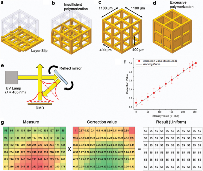
The developed PμSL is based on a bottom-up process. The first layer is cured on the build plate, and then, the next layer is accumulated sequentially. It is important to study the curing of the first layer because it determines the quality of the full printed 3D structure. If the first layer is incompletely attached to the build plate, it may cause a defect, as shown in Figure 2a. If the UV light is not sufficiently exposed and the resin is not fully cross-linked, the first layer may not stick to the build plate and could slip on the glass. It can cause the fabrication position to change, and consequently, the structure is shifted. Even if the resin is cured by the UV light, the fabricated structure could be twisted or collapse due to insufficient UV energy, as shown in Figure 2b. This is because an increase in UV energy increases the curing depth and hardness when the photocurable resin is photopolymerized.31 To fabricate a 3D microstructure that satisfies the target design, shown in Figure 2c, it is necessary to expose a sufficient amount of UV energy so that the cured resin has a robust property. If the exposure time is increased at a constant UV light intensity, the UV energy dose is increased, resulting in a greater cure depth. An excessive exposure time can result in greater scattering, which can lead to over-curing. The chain reaction and UV light scattering can cause the resin to cure even outside the fabrication area.32 Therefore, when excessive UV energy is exposed, unexpected area may also be cured, as shown in Figure 2d.
FIG. 2.
(a) Layer stacking error due to poor build plate adhesion of the first layer. (b) Weak bonding force between layers and shape distortion of the structure due to low energy. (c) Structures manufactured under proper energy conditions. (d) Over-curing due to excessive energy conditions. (e) A schematic of the UV lamp and DMD system. (f) Relationship between the intensity value and measured correction value of the DMD in the FOV. (g) Adjusted DMD output value based on the light intensity value in the lowest zone. DMD, digital mirror device; FOV, field of view; UV, ultraviolet. Color images are available online.
To pattern the resin uniformly with high accuracy, the intensity of the projected light pattern from the DMD should be uniform in the whole FOV area. As shown in Figure 2e, the reflecting mirror was used to coarsely center the position of the center Gaussian distribution of the UV LED on the DMD. However, the uniformity of the optical centering method was not effective due to the shape of the LED die and low uniform intensity coverage of the DMD from the LED source. Therefore, we additionally applied the grayscale mask compensation method to the PμSL system. In this method, the FOV area of the system was divided into 66 (11 rows and 6 columns) equal sections, and the intensity of each sectioned pattern was measured. In the developed PμSL system, the intensity of each pixel can be controlled by the 256 grayscale level using an 8-bit single channel. Moreover, the intensity was measured by a UV spectrometer (StellarNet, Inc., Blue-wave) between the ranges of 350 and 450 nm, as shown in Figure 2f. The maximum value at the 255 value was 40.43 mW/cm2. The minimum value at the 0 value was 4.12 mW/cm2 due to leaking light in the system. However, the intensity is actually 0 mW/cm2 because the LED is turned off when dark or there are blank images for which the value of the grayscale level is 0.
The measured intensity data in Figure 2g show a Gaussian distribution where the light generated by the UV source has the highest intensity at the middle bottom and weakens toward the outside of the beam. The value of 55, which had 10.10 mW/cm2, is the minimum value in the FOV area. As mentioned before, the DMD uses an 8-bit grayscale channel with pulse width modulation to control the UV intensity by controlling the time ratio at which the micromirror reflects the UV light. With this method, we can calculate a correction value map for adjusting the higher intensity value into the minimum value. The 66 zones of the DMD were adjusted using the correction value in Figure 2g calculated based on a minimum value of 55. Through this process, the UV light intensity of the manufacturable area was set uniformly.
Additive formability of the biomass
Photopolymerization characteristics of the biomass-based resin: working curve
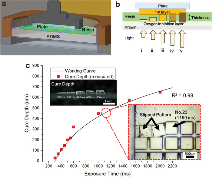
To cure the photocurable resin, radical polymerization is required. Curing occurs as free radicals react with the double bonds of monomers to form polymer chains. If exposure to oxygen occurs during this process, free radicals change the stabilized radicals, which have a low reactivity.33 The oxygen concentration of most photocurable resins is 10−3 mol/L. However, the oxygen concentration must be less than 10−6 mol/L for the radical polymerization reaction to occur. In this state, the photocurable resin is not polymerized because the oxygen concentration of the resin is larger than what is required for curing. Therefore, to start the radical polymerization, the oxygen dissolved in the resin must be consumed.34 UV light is one of the methods for reducing the oxygen concentration. Radical polymerization takes place at the lowered oxygen concentration and is attached to the interface. In the case of the bottom-up method, a resin may be stuck on the surface of the vat during the polymerization process. This problem can be solved by creating a PDMS window on the vat, shown in Figure 3a, because the porous structure of the PDMS prevents radical polymerization by creating an oxygen inhibition layer that supplies oxygen between the PDMS window and the interface of the resin.35 The polymerization occurs toward the previous layer where the oxygen concentration is depleted faster than the oxygen inhibition layer, resulting in the new layer being connected to the previous layer. However, if exposed to energy for a long time, the polymerization reaction can reach the oxygen inhibition layer, which may then stick to or damage the PDMS (Fig. 3b).
FIG. 3.
(a) Schematic diagram of the experiment to examine the adhesion conditions of the build plate and resin. (b) Curing of the resin according to the light energy: (i, ii) low energy, (iii) adequate energy, and (iv, v) excessive energy. (c) Comparison of the working curve of the biomass resin with the measured cure depth and curing test result of the resin and resin at a thickness of 500 μm. Color images are available online.
The curing thickness of the resin due to light absorption can be calculated mathematically. When UV light passes through the resin, some of the light is dispersed or absorbed on the surface of the resin. This effect can be defined by the depth at which the UV light penetrates. The intensity of the light is reduced exponentially by the Beer–Lambert law, and the energy term can be summed up in Equation (1) known as the cure depth equation.36 where Cd is the maximum curing thickness, Dp is the depth of the light penetration, Emax is the maximum exposure energy of the resin surface, and Ec is the critical energy at which the resin phase changes into a solid.
Printing patterns for evaluation the curing thickness against exposure time were designed. Patterns were created with a size of 800 × 800 μm, and the exposure time was set to a value of 300, 350, 400, 450, 500, 550, 600, 1000, 1500, and 2000 ms. To check the curing properties of the biomass-based resin exposed to the UV light, the biomass-based resin was placed on the vat without the build plate, and the material was cured according to the patterns. The cured thickness according to the various exposure times was measured using an optical microscope (MS-12Z-L1215; SEIWA Optical). The power of the UV lamp was measured using a spectrometer (PM100D; Thorlabs), and the exposure time was converted into an energy value. The measured thickness was defined as the Cd value, and each Dp value was calculated using Equation (1). The value of p is the average value of the Dp value calculated for each exposure time. The 347.4 μm value of p, which is the average of the Dp values, was applied to Equation (1) to derive a function to obtain the Cd value, as shown in Equation (2). Equation (2) is converted to a function of the exposure time (TExp), shown in Equation (3), for the convenience of the calculation. The value of −1981.46 is a constant K value obtained when converting the exposure energy into exposure time (TExp). In Figure 3c, the working curve is expressed using Equation (3) and compared with the measured value. The correlation between the cure depth and the exposure time of the biomass-based resin was investigated by theory and experiment. Equation (3) was able to make predictions similar to the actual measured values. Equation (3) can be used to select the exposure time for the desired curing thickness in 3D printing applications using biomass-based resins.
| (1) |
| (2) |
| (3) |
Resin and resin adhesion tests
Different conditions are required depending on whether the surface where the resin adhesion occurs is a build plate or a cured resin. Two adhesion tests were carried out: a resin and resin test and a build plate and resin test. In this article, we first describe the adhesion test for the resin and resin and then describe the adhesion test for the build plate and resin. Because the 3D microstructure is fabricated by layer-by-layer accumulation, it is necessary to study the adhesion tests of each layer. After confirming the process conditions of the first layer, an adhesion test between the previous and subsequent layers was carried out to perform the lamination process. Test patterns were created to expose 60 images from 50 to 3000 ms at 50 ms intervals. The first layer with a thickness of 500 μm was made on the build plate, and 60 patterns were made on the second layer. The patterns that did not adhere to the previous layer remained on the vat or slipped on the surface of the first layer, as shown in Figure 3c. Except for these patterns, we found patterns with an adhesion state in the previous layer. The experiment shows that the minimum exposure time for the adhesion test of the layer with a 500 μm thickness is 1150 ms.
Through experiments, it was confirmed that the second layer can be attached to the previous layer at an exposure time of 1150 ms when the distance from the previous layer is 500 μm. To compare with the calculated value, it was calculated by substituting 1150 ms into the TExp value of Equation (3), which is a working curve function. As a result, a Cd value of 485.2 μm was obtained for the exposure time of 1150 ms. Because the calculated results from the working curve function of Equation (3) had similar results as the actual experimental values, it was verified that Equation (3) can be used to determine the exposure time for various process thicknesses.
Adhesion test of the build plate and resin
Until recently, studies on adhesion of fused deposition modeling (FDM) have been reported.37–39 Similarly, the PμSL method should also study adhesion in the initial stage of the process. It is important to conduct an adhesion test of the build plate and resin. If the adhesion between the build plate (Glass) and the resin is too weak, problems may occur with the initial fabrication. In contrast, if the adhesion is too strong, printing is possible because there is no problem in the initial stacking; however, after the printing is completed, it may be difficult to take out the printed structure from the build plate or the printed structure may be broken.
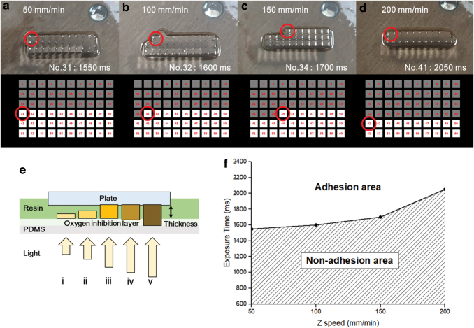
The adhesion test was performed by using a build plate raising adhesion test. For the first layer to be attached to the build plate, the build plate and the first layer must be stronger than the stresses caused by the first layer and the uncured resin when the build plate is raised for the next layer. The force generated when two plates with a viscous fluid are separated is called the Stefan adhesion defined in Equation (4).40 Here, R is the radius of the plate being separated, h is the distance between the two plates, η is the viscosity of the fluid, and dh/dt is the separation rate. This equation shows that when the build plate is raised for the next layer stacking, the force received by the previous layer is linearly proportional to the separation speed and proportional to the fourth power of the previous layer radius. To find the process conditions of the first layer, the biomass-based resin was placed in a vat coated with PDMS shown in Figure 3a, and the thickness in Figure 4e was set to 500 μm. As shown in Figure 4, 60 square images were created, and the exposure time of each image was sequentially exposed from 50 to 3000 ms at 50 ms intervals. After the process was completed, the build plate was raised at a speed of 100 mm/min. As a result, they could not be hardened sufficiently with low energy; thus, they could not have adhered to the build plate. Adhesion began on the build plate from the 32nd image (Fig. 4b), indicating that the first layer requires an exposure time of over 1600 ms.
FIG. 4.
Schematic diagram of the adhesion test results for the adhesion condition of the build plate and resin according to the Z-axis rising speed: (a) 50 mm/min, (b) 100 mm/min, (c) 150 mm/min, and (d) 200 mm/min. (e) Curing of the resin according to the light energy: (i, ii) low energy, (iii) adequate energy, and (iv, v) excessive energy. (f) Exposure time required for the build plate adhesion depending on the Z-axis speed. Color images are available online.
| (4) |
Next, the correlation between the build plate adhesion and resin on the velocity of the Z-axis was confirmed. An experiment was carried out in the same manner as the adhesion test for the build plate and resin, and the thickness of the first layer was set to 500 μm. After the process was completed, the experiment was performed by changing the build plate rising speed to 50, 150, and 200 mm/min for comparison with the existing 100 mm/min. After that, the remaining pattern was confirmed. As a result, it was confirmed that the rising speed of the Z-axis influences the number of remaining patterns (Fig. 4a–d). This means that as the rising speed of the Z-axis becomes faster, a longer exposure time is required for the first layer to adhere to the build plate. In Figure 4d, the exposure time of pattern 41, 2050 ms, becomes the minimum attachment condition of the first layer at a speed of 200 mm/min for a 500 μm thickness. The minimum exposure time according to the Z-axis velocity for the adhesion of the build plate and the first layer can be observed in Figure 4f. In Figure 4f, adhesion errors can occur at exposure times that are shorter than the required exposure time for the Z-axis speed, and adhesion errors will not occur at exposure times longer than the required exposure time.
According to the Stefan adhesion expressed by Equation (4), the stress generated when the separation speed is doubled is also doubled. Therefore, the first layer cured with an exposure time of 2050 ms at a speed of 100 mm/min has an adhesion twice as strong as the stress generated with an exposure time of 1600 ms at a speed of 100 mm/min. Based on these results, the first layer curing condition for a 500 μm thick biomass-based resin was determined to be 2050 ms, and all other subsequent experiments were performed with this curing condition.
Results and Applications
In this study, it was confirmed that a biomass-based resin with low biotoxicity can be used in the additive manufacturing process. It was confirmed that additive manufacturing is possible by applying the PμSL process, and various shapes were manufactured using the process conditions confirmed through experiments. Equation (3) shows the exposure time for the desired process thickness through the working curve of the biomass-based resin. In addition, the exposure time of the first layer can be determined through the build plate adhesion test results, as shown in Figure 4f.
The first layer was fabricated with a thickness of 500 μm, and the exposure time was set to 2050 ms, which is the 500 μm condition, as shown in Figure 4. The layer thickness was set to 20 μm. The exposure time was determined to be 2.5 times the processing thickness to improve the adhesion between the layers and the strength of the final structure. The exposure time of 350 ms can be calculated from Equation (3).
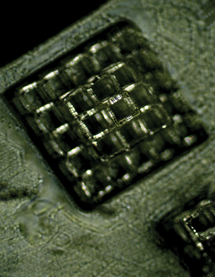
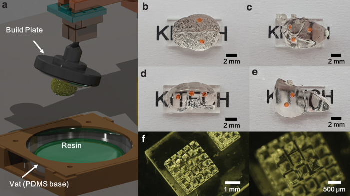
As a result, build plate adhesion errors in the product did not occur, and it was confirmed that the structure was fabricated without a shape error. Biostructures applicable to bio-applications can be fabricated, as shown in Figure 5. Figure 5f shows the 3D microscaffold for bio-applications. Because it was fabricated with a biocompatible biomass-based resin, it is expected to be used in future cell culture and bioengineering research.
FIG. 5.
Biostructure fabrication. (a) A schematic diagram of the finished product. (b) Brain shape sample. (c) Heart shape sample. (d) Kidney shape sample. (e) Liver shape sample. (f) 3D microscaffold for bio-applications. Color images are available online.
Conclusions
Biomass-based resins have a low toxicity and are expected to have a variety of bio-applications when producing 3D microstructures. In this article, a UV curable biomass-based resin was designed. The PμSL process was developed to produce 3D microstructures using the biomass-based resin, and the process conditions of the biomass-based resin were studied by using the PμSL. The following results were found: () the cure depth of the biomass-based resin according to the exposure time was confirmed through the working curve; () an adhesion test between the biomass based resin and the resin was carried out, and the results were confirmed to fit the working curve; () a curing test was performed to confirm the build plate adhesion state of the first layer, and the adhesion state according to the processing speed was confirmed to increase the success rate of the build plate adhesion of the first layer. Through the experiment, when the Z-axis speed was 100 mm/min, the exposure time of the first layer was set to 2050 ms to double the adhesion with the build plate. In addition, to improve the strength of the structure, the process exposure time at a layer thickness of 20 μm was set to 350 ms, which is 2.5 times the layer thickness. Using the optimized process conditions, a structure that can be applied to a 3D bio-applied device was fabricated. Therefore, in the future, if biomass-based resins are used in 3D printing process technology based on PμSL, the biomass-based resins can be used in various applications.
Author Disclosure Statement
No competing financial interests exist.
Funding Information
This work was supported by Technology innovation development business (No. PSE19650) funded by the Ministry of SMEs and Startups. This work was also supported by the Korea Institute of Industrial Technology (KITECH) internal project.
References
- 1. Ambrosi A, Pumera M. 3D-printing technologies for electrochemical applications. Chem Soc Rev 2016;45:2740–2755. [DOI] [PubMed] [Google Scholar]
- 2. Thompson MK, Moroni G, Vaneker T, et al. Design for additive manufacturing: Trends, opportunities, considerations, and constraints. CIRP Ann Manuf Technol 2016;65:737–760. [Google Scholar]
- 3. Stansbury JW, Idacavage MJ. 3D printing with polymers: Challenges among expanding options and opportunities. Dent Mater 2016;32:54–64. [DOI] [PubMed] [Google Scholar]
- 4. Melchels FPW, Feijen J, Grijpma DW. A poly(d,l-lactide) resin for the preparation of tissue engineering scaffolds by stereolithography. Biomaterials 2009;30:3801–3809. [DOI] [PubMed] [Google Scholar]
- 5. Lu Y, Mapili G, Suhali G, et al. A digital micro-mirror device-based system for the microfabrication of complex, spatially patterned tissue. J Biomed Mater Res Part A 2006;77A:396–405. [DOI] [PubMed] [Google Scholar]
- 6. Kowsari K, Akbari S, Wang D, et al. High-efficiency high-resolution multimaterial fabrication for digital light processing-based three-dimensional printing. 3D Print Addit Manuf 2018;5:185–193. [Google Scholar]
- 7. Wang Z, Martin N, Hini D, et al. Rapid fabrication of multilayer microfluidic devices using the liquid crystal display-based stereolithography 3D printing system. 3D Print Addit Manuf 2017;4:156–164. [Google Scholar]
- 8. Hofmann M. 3D printing gets a boost and opportunities with polymer materials. ACS Macro Lett 2014;3:382–386. [DOI] [PubMed] [Google Scholar]
- 9. Sachs E, Cima M, Cornie J. Three-dimensional printing: Rapid tooling and prototypes directly from a CAD Model. CIRP Ann Manuf Technol 1990;39:201–204. [Google Scholar]
- 10. Liravi F, Vlasea M. Powder bed binder jetting additive manufacturing of silicone structures. Addit Manuf 2018;21:112–124. [DOI] [PMC free article] [PubMed] [Google Scholar]
- 11. Minetola P, Iuliano L, Marchiandi G. Benchmarking of FDM machines through part quality using IT Grades. Proc CIRP 2016;41:1027–1032. [Google Scholar]
- 12. Mohamed OA, Masood SH, Bhowmik JL. Experimental investigation of time-dependent mechanical properties of PC-ABS prototypes processed by FDM additive manufacturing process. Mater Lett 2017;193:58–62. [Google Scholar]
- 13. Kimura T, Nakamoto T, Mizuno M, et al. Effect of silicon content on densification, mechanical and thermal properties of Al-xSi binary alloys fabricated using selective laser melting. Mater Sci Eng A 2017;682:593–602. [Google Scholar]
- 14. Thijs L, Verhaeghe F, Craeghs T, et al. A study of the microstructural evolution during selective laser melting of Ti-6Al-4V. Acta Mater 2010;58:3303–3312. [Google Scholar]
- 15. Bhatt PM, Kabir AM, Peralta M, et al. A robotic cell for performing sheet lamination-based additive manufacturing. Addit Manuf 2019;27:278–289. [Google Scholar]
- 16. Heigel JC, Michaleris P, Reutzel EW. Thermo-mechanical model development and validation of directed energy deposition additive manufacturing of Ti-6Al-4V. Addit Manuf 2015;5:9–19. [Google Scholar]
- 17. Saboori A, Gallo D, Biamino S, et al. An overview of additive manufacturing of titanium components by directed energy deposition: Microstructure and mechanical properties. Appl Sci 2017;7:883–905. [Google Scholar]
- 18. ISO/ASTM 52900:2015(en). Additive Manufacturing—General Principles: Part 1: Terminology. Geneva, Switzerland: International Organization for Standardization, 2015. [Google Scholar]
- 19. Lee MP, Cooper GJT, Hinkley T, et al. Development of a 3D printer using scanning projection stereolithography. Sci Rep 2015;5:9875–9879. [DOI] [PMC free article] [PubMed] [Google Scholar]
- 20. Murakami T, Yada T, Kobayashi G. Positive direct-mask stereolithography with multiple-layer exposure: Layered fabrication with stair step reduction. Virtual Phys Prototyp 2006;1:73–81. [Google Scholar]
- 21. Melchels FPW, Feijen J, Grijpma DW. A review on stereolithography and its applications in biomedical engineering. Biomaterials 2010;31:6121–6130. [DOI] [PubMed] [Google Scholar]
- 22. Hull CW, Arcadia C. Apparatus for Production of Three-Dimensional Objects by Stereolithography. U.S. Patent No. 4,575,330. 1984. [Google Scholar]
- 23. Kodama H. Automatic method for fabricating a three-dimensional plastic model with photo-hardening polymer. Rev Sci Instrum 1981;52:1770–1773. [Google Scholar]
- 24. Sun C, Fang N, Wu DM, et al. Projection micro-stereolithography using digital micro-mirror dynamic mask. Sensors Actuators A Phys 2005;121:113–120. [Google Scholar]
- 25. Ware HOT, Farsheed AC, Akar B, et al. High-speed on-demand 3D printed bioresorbable vascular scaffolds. Mater Today Chem 2018;7:25–34. [Google Scholar]
- 26. Oskui SM, Diamante G, Liao C, et al. Assessing and reducing the toxicity of 3D-printed parts. Environ Sci Technol Lett 2016;3:1–6. [Google Scholar]
- 27. Kristufek TS, Kristufek SL, Link LA, et al. Rapidly-cured isosorbide-based cross-linked polycarbonate elastomers. Polym Chem 2016;7:2639–2644. [Google Scholar]
- 28. Feng X, East A, Hammond W, et al. Thermal analysis characterization of isosorbide-containing Thermosets: Isosorbide epoxy as BPA replacement for thermosets industry. J Therm Anal Calorim 2012;109:1267–1275. [Google Scholar]
- 29. Kim S, Cho JK, Shin S, et al. Photo-curing behaviors of bio-based isosorbide dimethacrylate by irradiation of light-emitting diodes and the physical properties of its photo-cured materials. J Appl Polym Sci 2015;42726:1–8. [Google Scholar]
- 30. Rose M, Palkovits R. Isosorbide as a renewable platform chemical for versatile applications-quo vadis? Chem Sus Chem 2012;5:167–176. [DOI] [PubMed] [Google Scholar]
- 31. Lee JH, Prud'homme RK, Aksay IA. Cure depth in photopolymerization: Experiments and theory. J Mater Res 2001;16:3536–3544. [Google Scholar]
- 32. Lehtinen P, Laurila S, Kaivola M, et al. Controlling penetration depth in projection stereolithography by adjusting the operation wavelength. Key Eng Mater 2014;611–612:756–762. [Google Scholar]
- 33. Andrzejewska E, Lindén LÅ, Rabek JF. The role of oxygen in camphorquinone-initiated photopolymerization. Macromol Chem Phys 1998;199:441–449. [Google Scholar]
- 34. Santoliquido O, Colombo P, Ortona A. Additive manufacturing of ceramic components by digital light processing: A comparison between the “bottom-up” and the “top-down” approaches. J Eur Ceram Soc 2019;39:2140–2148. [Google Scholar]
- 35. Janusziewicz R, Rolland JP, Tumbleston JR, et al. Continuous liquid interface production of 3D objects. Science (80-) 2015;347:1349–1352. [DOI] [PubMed] [Google Scholar]
- 36. Schaeffer P, Bertsch A, Corbel S, et al. Industrial photochemistry XXIV. Relations between light flux and polymerized depth in laser stereophotolithography. J Photochem Photobiol A Chem 1997;107:283–290. [Google Scholar]
- 37. Kozior T, Mamun A, Trabelsi M, et al. Electrospinning on 3D printed polymers for mechanically stabilized filter composites. Polymers (Basel) 2019;11:2034. [DOI] [PMC free article] [PubMed] [Google Scholar]
- 38. Kozior T, Döpke C, Grimmelsmann N, et al. Influence of fabric pretreatment on adhesion of 3D printed material on textile substrates. Adv Mech Eng 2018;10:1–8. [Google Scholar]
- 39. Kozior T, Trabelsi M, Mamun A, et al. Stabilization of electrospun nanofiber mats used for filters by 3D printing. Polymers (Basel) 2019;11:1618. [DOI] [PMC free article] [PubMed] [Google Scholar]
- 40. Barnes WJP. Functional morphology and design constraints of smooth adhesive pads. MRS Bull 2007;32:479–485. [Google Scholar]


