

Abstract
Additive manufacturing (AM) brings new design potential compared with traditional manufacturing. Nevertheless, traditional manufacturing knowledge remains embedded in the minds of designers and is a real cognitive barrier to design in AM. Design for Additive Manufacturing (DfAM) provides tools, techniques, and guidelines to optimize design with the specifics of AM. These methods are usable at different moments of the design process. Only few DfAMs focus on the early stages of design, the ideation phase, which allows for the most innovation. The literature highlights the effectiveness of methodologies based on tangible tools, such as cards or objects, to generate creativity. The difficulty with such tools is to be inspirational as well as formative. Therefore, this article presents a method to help designers capture the design potential of AM to design creative solutions at the early stages of product design, named the Augmented Design with AM Methodology (ADAM2). This methodology relies on the potential of AM, defined in 14 opportunities and a set of 14 inspirational objects, each representing an opportunity. Dedicated to creativity sessions, this methodology allows forcing the association between knowledge of a company's sector and the design potential of AM. To validate the effectiveness of the ADAM2 methodology, we use it for an industrial application in a jewelry and watchmaking company. The results showed that ADAM2 promote the generation of creative solutions and the exploitation of the design potential of AM during the early design stages.
Keywords: creativity, Design for Additive Manufacturing, tangible objects, creative design

Introduction
Additive manufacturing (AM) is now a mainstream technology in the industry, particularly in motor vehicles, aerospace, and industrial machines.1 The current situation shows a very important development of this technology. More and more companies are using this technology for the production of industrial parts, and not exclusively for prototyping.1
In this article, we focus on the technological axis of AM. AM technologies differ from the two traditional manufacturing processes of formative manufacturing (such as casting or forging) and subtractive manufacturing (such as machining). AM is a generative manufacturing process that allows a physical object to be made layer by layer from a digital object.
AM allows to exceed some limits of traditional manufacturing.2 AM, through its design potential, solves complexities inherent to traditional manufacturing. Gibson et al. have defined these complexities: shape complexity, hierarchical complexity, functional complexity, and material complexity.3 The design potential of AM makes it possible to improve existing products, or even to manufacture objects that could never have been manufactured before.4
However, very few methodologies are proposed to assimilate this technical potential to improve design by encouraging creativity and innovation.
After presenting the background, this article focuses on the following research question: How to promote the assimilation of the technical potential of AM to encourage creativity in product design? To answer this research question, we will focus on the Augmented Design with AM methodology (ADAM2). We will apply it to an industrial use case to measure its efficiency.
Background
Design support methodologies specific to traditional manufacturing are not effective for design in AM.4 The ingrained knowledge of traditional manufacturing in the minds of designers is an impediment to AM design.5 This knowledge is a cognitive barrier because designers have learned and continue to learn the fundamentals of design in these manufacturing processes.6 To overcome these barriers, several research projects propose methodologies to help design in AM: Design for Additive Manufacturing (DfAM). DfAM refers to the set of methodologies providing designers with concrete tools, techniques, and guidelines to optimize the design with the specificities of AM.4
Booth et al. characterize DfAM in three groups: AM technologies, DfAM guidelines, and design methods.7
Methodologies focusing on the technological aspects of AM present the boundaries of the technology to consider during product design. For example, some methodologies will present solutions to the volume constraints of machines.8 These methodologies are very useful for the creation of Computer Aided Design (CAD) models.
The main objective of the design guidelines is to present the specificities of the different AM processes.2 These guidelines focus on the design phase between the creation of the CAD model and the manufacture of the prototype.7
The group “design methods” is divisible into two sets: the computational design tool and the general DfAM process.9 Computational design tool aims to help designers to integrate the geometric freedoms offered by additive manufacturing technologies during the design phase, as well as the process limitations (process technology and materials).9 Thus, there are computer tools for topological optimization or for the study of geometries.10 These computer tools will operate during the creation of CAD models. Methods are available for the entire design process. These methods mainly rely on the integration of the knowledge of AM in the early stages of design and then reuse them during the rest of the process. Laverne et al. offer a methodology that integrates AM knowledge at several distinct moments in the product design process.11
The different methodologies do not have the same objectives because they operate at different moments in the design process. There are three phases where it is possible to use a methodology that helps designers (Fig. 1): the ideation phase (early-stage design phase), the development phase (between the definition of a concept and the creation of a CAD model), and the elaboration phase (between the CAD model and the prototype).12
FIG. 1.

Product design process. CAD, Computer Aided Design.
During the ideation phase, major design decisions take place.9,13 It is important to introduce the specifics of AM during the early design phases for two main reasons: th e first is to generate creativity,13 and the second is to introduce the knowledge of this technology as early as possible to overcome the specifics of traditional manufacturing.6,14,15
To foster the generation of innovation, it is important to take into account creativity in a design aid methodology to free oneself from the existing forms and functions of the products.16 Creativity is essential for product design and innovation.17 There is quite a number of tools to promote creativity in design sessions: purge, brainstorming, mind map, etc. These tools are general and not specific to AM. Some authors rely on more tangible tools that can more easily bring knowledge in AM and try to integrate it in a creative process.
Several authors have explored the use of card-based approaches to enhance creativity in DfAM. The cards represent characteristics of the potential of AM or objects in AM representative of this technology.18–20 The use of representations in the form of cards allows designers to have a starting point for their ideas that does not depend on traditional manufacturing processes. Some authors based their methodology around a set of tangible objects.9,21,22 The manipulation of objects encourages the generation of creative ideas and concepts.13 The purpose of these objects is to guide designers toward the design potential of AM.
The handling of objects allows one to become familiar with and better understand the technical specificities of AM. The objects present in the literature are conceived either as benchmarks of the possibilities for a type of material,22 or through an object representing a particularity of AM present on an existing part,19,21 or through heuristic designs based on a set of existing products.9
The DfAMs based on a set of tangible objects are presented by objects with existing product designs,9,19 are relying on AM processes,22 or try to present simultaneously the capabilities and limitations of the technology.20 The limit of these methods is therefore not to have a high enough level of abstraction for creativity and to be more or less adapted according to the sectors. During a creative approach in the early design phase, it is important to get out of the existing architectures and the constraints and limits of a technology.23
The difficulty of methodologies based on tangible objects is the alliance between objects that are as neutral as possible, allowing a high level of creative inspiration, and objects that best present the potential of AM by having a formative function on this technology. The challenge of a methodology based on tangible objects is to promote the generation of creative solutions and the exploitation of the potential of AM during the early stages of design.
ADAM2: Augmented Design with AM Methodology
The ADAM2 aims to introduce the potential of AM in a design session to stimulate creativity through inspirational objects. The ADAM2 methodology uses objects representing the opportunities of AM. We introduce these objects in a design process based on the process proposed by Rias et al.13 It presents a process forcing the association between knowledge specific to the company's field of expertise and knowledge on AM in early-stage design. In our case, the objects presenting AM opportunities will represent the knowledge on AM.
Opportunities in AM
For each of Gibson's complexities, using the literature and a large number of AM products, we classified existing technical solutions that offer design potential compared with traditional manufacturing. From this classification, we have identified 14 characteristics that define the potential of AM, which we have called the opportunities of AM. We use the term “opportunity” in reference to opportunistic DfAM methods, which are methods designed to help designers explore the technical complexity offered by AM.23 These methods are distinct from those that will introduce the new constraints of the technology.24
Opportunities associated with shape complexity
Freeform shapes: AM is a process of adding material layer by layer. This feature allows the designer to think of the piece as an addition of two-dimensional (2D) elements to give a three-dimensional (3D) set.25 A complexity of a 2D element is much easier to solve than a shape complexity in 3D. Almost any shape can be built,4 and this freedom of shapes has a real impact on design decisions.26,27
Objects from 3D scans: By combining 3D scanning techniques and AM, product design is customizable.28,29 This opportunity highlights the ability of designing on the basis of an existing geometry to improve product properties.30
Opportunities associated with hierarchical complexity
Microstructure variation: In AM, it is possible to vary the structure on a microscopic level.31 This variation can be carried out through an adaptation of the porosity,32 which can then be used to influence the mechanical, physical, and technical properties.33
Texture: It is possible to vary the roughness of the surface and therefore the texture.34–36 The texture can lead to surface mechanical properties of the surface or structural mechanical properties.37 Moreover, the texture of a product can have a strong influence on the use of a product, so it is important to take texture into account when designing a product.38
Opportunities associated with functional complexity
Monoblock: AM makes it possible to reduce the number of components in an assembly by integrating several parts to be assembled into a single piece. It eliminates the assembly steps. A monoblock design imposes to think about the absence of assembly processes from the early stages of design.28,39
Topology optimization: With the finite elements analysis, it is possible to optimize the material in volumes subject to constraints; it allows a reduction in the mass of the products. AM makes it possible to push topological optimization thanks to organic geometries unfeasible with other manufacturing processes. This opportunity influences the mechanical, physical, and technical properties of the product.40–42
Nonassembled mechanisms: In AM, it is possible to make kinematic joints, which means to make mechanical connections during manufacturing. Considering a mechanism in the manufacturing phase implies new considerations for designers43,44; the product must be studied as a system of components.45,46
Segmentation: It is possible to manufacture the parts of an assembly separately to create a kit. This opportunity responds to the size constraints of printers, which forces designers to decompose a product into several parts.47,48 This design in kit allows the manufacturer to remanufacture only defective parts.49
Embedded components: In AM, it is possible to encapsulate an element in a part during the manufacturing. This inclusion of elements does not present an assembly joint line as in traditional inclusion processes. It is thus possible to integrate electronic elements into the part,50 or to increase the mechanical properties by integrating fibers.44
Internal channels: AM makes it possible to design an internal channel during manufacturing.51 The performance of a product can be improved thanks to heat exchangers.52,53 Integrating the internal channels into the manufacturing process reduces the risk of leaks and reduces the weight of the part.39
Infilling: AM enables us define internal filling patterns.54,55 Thus, the shapes inside the structure can be adjusted as needed. This opportunity influences not only the mechanical, physical, and technical properties of the objects56 but also the costs.57
Auxetics structure: The AM technology permits us to modify Poisson's module and to have a negative module by acting on the internal structure. This opportunity makes it possible to transmit stresses in the structure by deformation,58 or even to absorb stresses by deformation and compression.59 This opportunity is often referred to by the term “metamaterials” in AM in various studies.
Opportunities associated with material complexity
Material choices: AM gives the possibility to work with a large choice of materials: plastic, metal, ceramic, sand, composite, etc. These different materials have different economic, physical, mechanical, optical, and electrical properties,60 making it possible to adapt the choice of material to the challenges of the field of application, particularly for medical purposes.61
Multimaterials: Some AM machines allow the design of multimaterial parts. It is thus possible to manufacture composite materials with several plastics,62 to mix different metals and even to combine materials of different nature.63,64
Physical representation of the opportunities
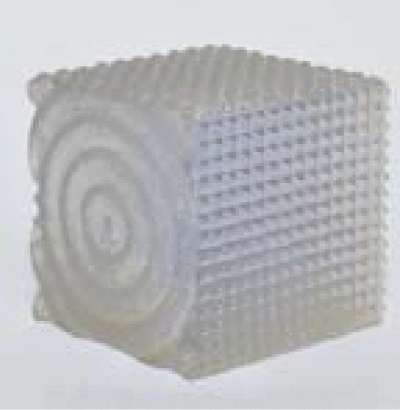
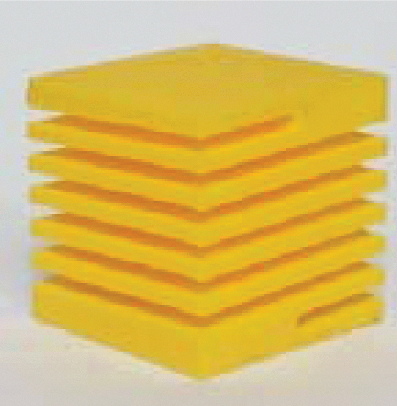
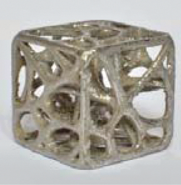
The “opportunity objects”
The objects should be as neutral as possible in their general form and at the same time to represent the opportunity as well as possible. Using the literature on inspirational objects in the design process,65,66 we choose cube-shaped objects with a size of 3 cm on each side (Table 1).
Table 1.
The “Opportunity Objects”
| Opportunity | Machine | Materials | Description | Schema | Object |
|---|---|---|---|---|---|
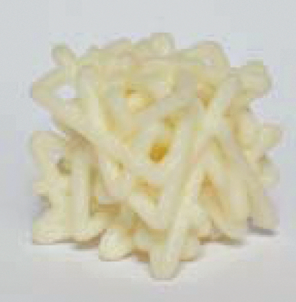
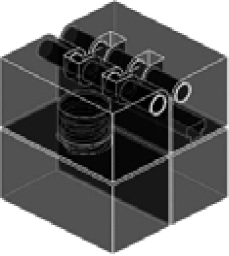
| Freeform shapes | Stratasys Dimension ELITE | P430 ABSplus (Support P400-SR) | Cube with a tube forming a complex node |

|
|
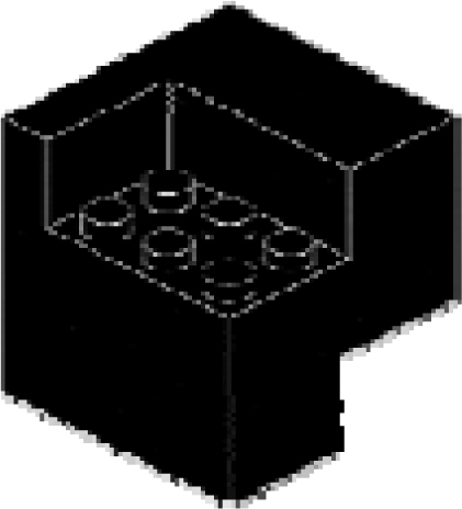
| Objects from 3D scans | Stratasys Objet260 Connex | FullCure 810, VeroClear | Cube with scans of surfaces of Lego® parts |
|
|
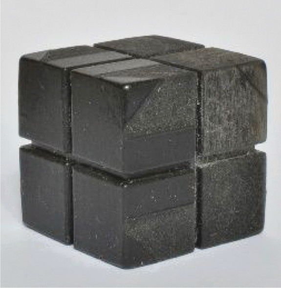
| Microstructure variation | Stratasys Objet260 Connex | FullCure 980, TangoBlack Plus | Cube with eight parts with different porosities and thus different hardness levels |

|
|
| Texture | Stratasys Objet260 Connex | FullCure 810, VeroClear | Cube representing a different texture per face |
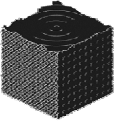
|
|
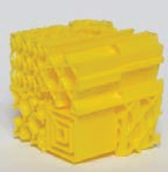
| Monoblock | MakerBot Replicator 2 | Yellow PLA | Spiral-shaped cube with a central column |

|
|
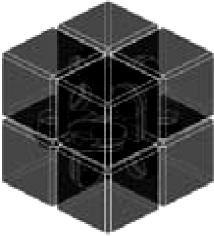
| Topology optimization | SLM®125 | Fe-based Alloy 316L (1.4404) | Cube with an organic structure |

|
|
| Nonassembled mechanisms | MakerBot Replicator 2 | Yellow PLA | Cube with pivot, slide, and helical connections |
|

|
| Segmentation | Stratasys Objet260 Connex | FullCure 810, VeroClear | Cube made in one piece can be disassembled into four parts |
|

|
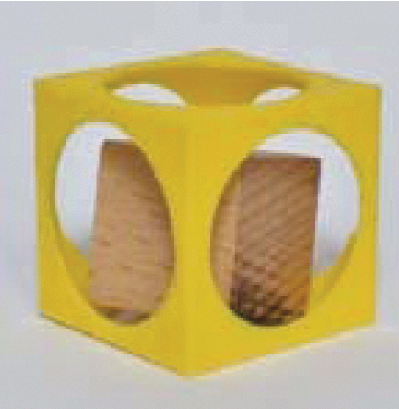
| Embedded components | MakerBot Replicator 2 | Yellow PLA | Cube encapsulating a nonremovable wooden cube |

|
|
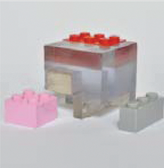
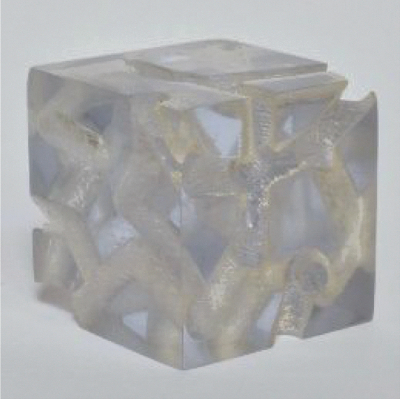
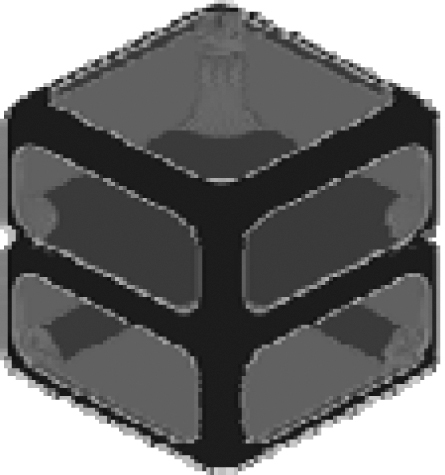
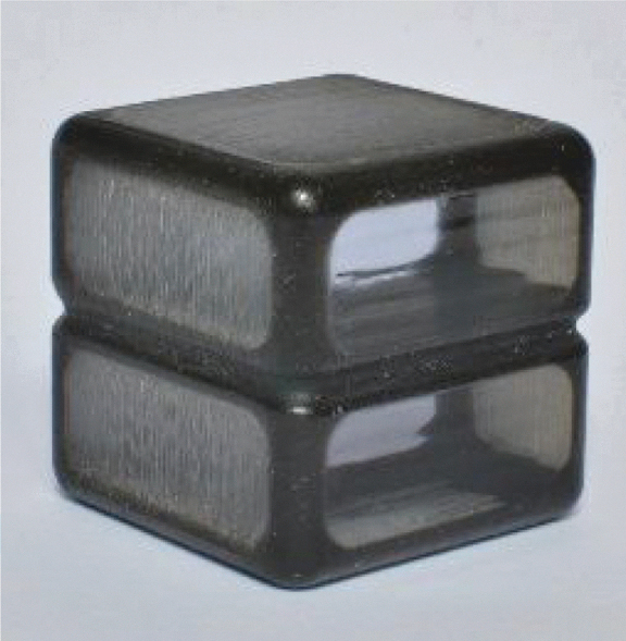
| Internal channels | Stratasys Objet260 Connex | FullCure 810, VeroClear | Transparent cube with internal channels |
|
|
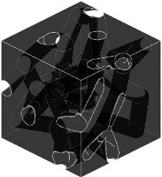
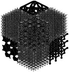
| Infilling | MakerBot Replicator 2 | Yellow PLA | Cube with eight different internal structures |
|
|
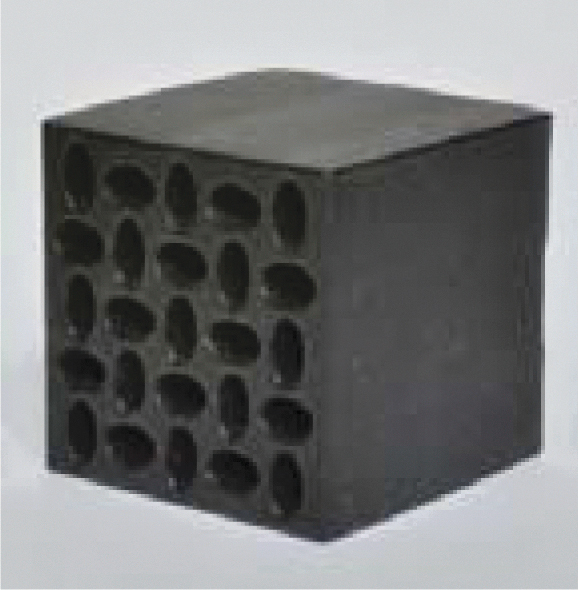
| Auxetics structure | Stratasys Objet260 Connex | FullCure 980, TangoBlack Plus | Cube with a structure allowing to have negative Poisson's modulus |

|
|
| Material choices | Stratasys Objet260 Connex Stratasys Dimension ELITE MakerBot Replicator 2 SLM125 |
FullCure 810, VeroClear FullCure 980, TangoBlack Plus P430 ABSplus (Support P400-SR) Yellow PLA Fe-based Alloy 316L (1.4404) |
Cube with five plates of different materials on one plate with a central column |

|

|
| Multimaterials | Stratasys Objet260 Connex | FullCure 810, VeroClear FullCure 980, TangoBlack Plus |
Cube made in one piece of two different materials |
|
|
Correction added on May 24, 2021 after first online publication of May 6, 2021: The right most figure for the “Internal Channels” row was the incorrect figure. The right most figure has been replaced with the correct figure.
We have chosen to present one opportunity per object to facilitate the understanding of the different opportunities, especially for novice designers in AM.
We use three types of processes: selective laser melting SLM (SLM®125), material jetting polyjet (Stratasys Objet260 Connex), and fused deposition modeling FDM (Stratasys Dimension ELITE and MakerBot Replicator 2).
Evaluation of the “opportunity objects”
The above objects are represented according to their final design. Before using these objects in a creativity session, we wanted to have the cubes evaluated to validate their design in relation to the opportunity associated with each one. It allowed us to adapt and improve the designs to avoid any comprehension bias when using the tool.
Thus, the opportunity objects were evaluated by three samples. The first sample consisted of 18 students of different nationalities in the final year of master's degree in Management Engineering. The second sample involved six engineering professors from three European universities. The third sample consists of five industrialists from five companies based in Europe. These industrialists work in product design and are interested in AM as a potential for their company's activity.
The evaluation consisted of carrying out an analysis by verbalization of the objects. Each participant had the object in their hands for 1 to 2 min and had to write down all the words that came to mind.
The objective of this evaluation is to have the opportunity name or a synonym spelled out to validate the design of the objects or improve them. For example, for the “embedded components” opportunity, the synonyms cited were inclusion, encapsulation, and “Russian dolls.”
As the creativity sessions are conducted in groups, the design of the objects can be validated if at least one person in two or three gives at least one synonym.67 For each participant, a score of 1 was given when he or she gave the name of the opportunity or a synonym, and a score of 0 when he or she did not. Each sample has a weight of one third.
Figure 2 shows the results. Above 50%, the object is understood by one person out of two; between 33% and 50%, the object is understood by one person out of three; and below 33% the object is understood by less than one person out of three.
FIG. 2.

Evaluation of the “opportunity objects.”
For each object, a score between 0 and 1 is obtained. With the words given by the participants, we validated eight objects. We were able to observe words highlighting design biases, which allowed us to improve or adapt the design of certain objects. Moreover, the evaluation pointed out important design similarities between some cubes, forcing them to increase the disparities between them. The first batch of objects was entirely made of plastic material; the panel of industrialists informed us that the presence of metal objects in the batch would make it more attractive to professionals. The evaluation highlighted the difficulty of understanding the object associated with the monoblock opportunity.
Thus, this evaluation made it possible to improve the design of four objects (texture, monoblock, segmentation, multimaterials) and to integrate metal into the design of two objects (topology optimization, material choices).
The new designs of the objects received validation following a new presentation of them to the groups of academics and industrialists. The remarks of the participants highlighted that a short presentation of the “opportunity objects” before their use in the creativity session could improve the understanding of the latter.
Case Study
After the validation of the “opportunity objects,” we can use them for a case study with designers in a company. The company is a group specializing in the luxury goods industry, which includes several brands, particularly in the watch and jewelry sectors. The case study includes two workshops with engineers and designers from several brands of the group, all working in product design. The participants were not the same in the two workshops. As the two groups did not have the same number of participants, the designers worked in dyads on the different phases of creativity, problem analysis, and design.
The structure of the two workshops was equivalent. Figure 3 presents the session protocol with the objective, the participant profiles, the plan, the tools used, and the deliverables. The difference between the two workshops appears during the inspiration phase. The first group works with “AM object cards,” while the second group works with the “opportunity object.”
FIG. 3.

Protocol mapping. AM, additive manufacturing.
Results
Generating creative solutions
To evaluate the level of creativity, we chose five judges who are experts in innovation or product design. For this purpose, all ideas developed were sent to the judges with evaluation criteria.
Evaluation criteria
Four criteria for evaluating creativity were defined, based on the work of the “P's of Creativity” (Process, Product, Person, and Place),68,69 and more specifically on the criteria for product creativity.70,71
The four evaluation criteria are as follows:
Relevance: The concept meets the requirements of the problem from a use and performance point of view (e.g., the concept seems to do what it is supposed to do, the concept seems easy to use, the concept meets the objectives).
Improvement (incremental innovation): The concept draws on external knowledge to improve the existing product (e.g., the concept draws attention to gaps in existing products, the concept shows how existing products could be improved, the concept uses existing knowledge to generate novelty).
Elegance: The concept is elegant because the solution is at the same time efficient, parsimonious, and intellectually satisfying, hence a certain esthetic feeling (e.g., one can immediately see that the concept makes sense, the concept is well finished and skillfully executed, the concept is surprisingly simple and is “smart”).
Vision (breakthrough innovation): The concept proposes new ways of approaching existing problems to innovate (e.g., the concept is designed with new bases, the concept transforms problems into advantages, the concept brings a product that does not yet exist).
Evaluation by judges
Each judge had to evaluate the 13 detailed ideas according to the 4 criteria on a Likert scale with 5 answer choices, from 1 “Strongly Disagree” to 5 “Strongly agree.” Agreement among the judges proved acceptable for reliable analysis (α = 0.78) (Table 2).
Table 2.
Evaluation Table for Creativity Criteria
| Creativity criteria | IdeasGroup1 (n = 5) mean (SD) | IdeasGroup2 (n = 8) mean (SD) | DFbetween | DFwithin | Test F | p |
|---|---|---|---|---|---|---|
| Relevance | 3.36 (0.22) | 4.38 (0.13) | 1 | 11 | 114 | 4.10−7 |
| Improvement | 3.32 (0.23) | 4.50 (0.24) | 1 | 11 | 77.5 | 3.10−6 |
| Elegance | 2.96 (0.62) | 4.15 (0.30) | 1 | 11 | 22.1 | 7.10−4 |
| Vision | 2.92 (0.39) | 4.20 (0.43) | 1 | 11 | 29.4 | 2.10−4 |
With the aid of an analysis of variance study, we observe significant differences in the four creativity criteria. We observe a significant difference in the criterion of relevance. The ideas from group 2 put forward concepts with much more detailed technical characteristics. The contribution of knowledge in AM allowed the participants to focus, in more detail, on the use of the product. Thus, while the ideas from the first group look more like futuristic concepts, the ideas from the second group are more concrete and really address an existing need. The difference in average between the two groups is very significant on the criterion of breakthrough innovation (vision).
These results suggest that the ADAM2 methodology generated more creative solutions than the use of cards presenting AM products, thus validating the hypothesis of fostering creative solutions.
Exploitation of the technical potential of AM
We also chose to conduct an evaluation by five judges, experts in AM or product design.
Evaluation criteria
Four criteria for evaluating the technical potential of AM were defined, based on Gibson's complexities.3
The four evaluation criteria are as follows:
Shape potential: The concept emphasizes the possibility of achieving any geometry through the use of AM (e.g., complex shapes, unique shape integration, surface properties).
Hierarchical potential: The concept highlights the possibility of improving the structural performance of the product through AM (e.g., weight reduction, improvement of mechanical properties [density, hardness, strength, adhesion], shape optimization).
Functional potential: The concept highlights the contribution of new functions thanks to AM (e.g., added secondary functions, modification of product functions over time, multiproduct in one).
Material potential: The concept highlights the use of several materials thanks to AM (e.g., multimaterial parts, choice of material independent of the design, same digital file for plastic or metal manufacturing).
Evaluation by judges
Each judge had to evaluate the 13 detailed ideas according to the 4 criteria on a Likert scale with 5 answer choices (Strongly Disagree, Disagree, Neutral, Agree, and Strongly Agree). Agreement among the judges proved acceptable for reliable analysis (α = 0.79) (Table 3).
Table 3.
Evaluation Table for Criteria for Additive Manufacturing Potential
| AM potential criteria | IdeasGroup1 (n = 5), mean (SD) | IdeasGroup2 (n = 8), mean (SD) | DFbetween | DFwithin | Test F | p |
|---|---|---|---|---|---|---|
| Shape potential | 3.24 (0.52) | 4.23 (0.27) | 1 | 11 | 20.7 | 8.10−4 |
| Hierarchical potential | 2.72 (0.27) | 4.18 (0.29) | 1 | 11 | 81.1 | 2.10−6 |
| Functional potential | 2.84 (0.43) | 4.00 (0.26) | 1 | 11 | 37 | 8.10−5 |
| Material potential | 2.76 (0.57) | 4.08 (0.37) | 1 | 11 | 25.8 | 4.10−4 |
AM, additive manufacturing.
From the judges' evaluation data on the potential of AM, significant differences are observed between the group that did not use our methodology and the group that did use it on the four criteria.
These results suggest that the ADAM2 methodology was more conducive to the exploitation of the technical potential of AM with the “opportunity object” than with the cards showing products in AM.
Discussion
While the evaluations show us that the use of objects is more efficient to generate creative solutions and to exploit the potential of AM, these workshops also allowed us to observe a real difference between the use of cards and the use of objects. Some participants from group 2 took a lot of time trying to interpret the “opportunity objects” for their ideas. As the handling of the objects was easy, we observed that the participants tended to take and retake the objects in their hands during the whole time of the conception of the ideas. Conversely, the participants in group 1 looked at the “AM object cards” at the beginning before putting them back on the table during the entire phase of the development of the ideas. The “opportunity objects” lead to much more discussion between the members of a dyad than the “AM object cards.” The time necessary to develop the idea before putting it on paper was longer with the objects; participants from group 2 had more difficulty finalizing the ideas within 10 min, whereas participants from group 1 had on average much more ease. To present the ideas to all participants, group 1 participants tended to use the luxury plates to argue their idea, while group 2 participants relied on the “opportunity objects.” There is a real difference between the ideas of the two groups, because in the first group the descriptions of the ideas are mainly general and form oriented, whereas in the second group the descriptions of the ideas already contain the basics of mechanical and technical properties, while still having descriptions on form. Reading the ideas of the two groups, one immediately observes that those of the second group are more complete and comprehensive. The consequence of this difference is that the drawings and sketches of the second group are more worked out, more detailed, and thus show a better coherence.
Moreover, participants were much more interested in technical issues using “opportunity objects” rather than “AM object cards.” The fact of having an object in their hands intrigues the participants who are interested in understanding how it is possible to manufacture this object; this aspect of curiosity about the manufacturing phase is much more absent with the “AM object cards.” The fact that the objects present opportunities in a “fairly neutral” way makes it easier for designers to interpret the potential of AM for products in their sector. With the AM images in the one group, designers either seem to set aside the “AM object cards” and not really consider the specificities for their idea, or they try to replicate almost the same thing for their idea.
Our results from an industry application case study highlighted the strength of our method during creativity sessions. Nevertheless, several limitations must be highlighted.
One of the limitations of our work is that the current version of the ADAM2 method is temporal. Indeed, we have taken into account the current state of technology and the designers' level of knowledge in AM. In the future, the method in its current state may become mainly a tool to assist creativity and less a formative tool. To ensure the effectiveness of the method, if AM technology offers new opportunities in the future, they will be added to the method. An augmented reality version may be offered to increase creativity and utilization.
We have a limit in terms of participants and groups. The industrial context of the experiment led to a different number of participants between the two groups depending on the availability of the employees and the company's own objectives. The workshop panels are not exactly representative of the population of designers in companies in terms of gender, age, or profession. All participants were volunteers for the workshops. Designers in the watch and jewelry industry may be more open to new technologies such as AM as designers in other industrial fields. Therefore, they were not reluctant to use new technology, but on the contrary they were very receptive to the use of new creativity tools. In addition, despite the fact that the participants were employees in a company and had a lot of skills in their professional field, their skills in AM were almost nonexistent for many of them. This aspect may, perhaps, explain the large gap between the results of the two groups. The contribution of “opportunity objects” allows much more knowledge to be assimilated than the contribution of “AM object cards.”
We have limits at the level of the protocol. Indeed, with our case study, we show a difference between the use of our methodology and the use of images of products in AM proposed by other methodologies. However, it would have been interesting to try other forms of tools such as videos of objects, or physical products in AM that are not inspirational objects.
Our findings open several research axes. This article aims to present a methodology allowing designers to appropriate the potential of AM during the early stages of design, but it does not show how the potential of this technology can be added to that of other manufacturing technologies. The integration of AM by designers is an important issue for design teams; but it is the ability to mix the potential of this technology with other technologies that will improve innovation processes. Furthermore, our method must evolve over time to remain effective and must be able to be adapted with new tools offering new potential for creativity, such as augmented reality.
Conclusion
This article presents the method ADAM2 that answers the research question: How to promote the assimilation of the technical potential of AM to encourage creativity in product design. To answer this question, we have integrated into a design process a set of inspirational objects in AM to promote the generation of creative solutions during the early stages of design and the exploitation of the technical potential of AM during the early stages of design. This methodology is based on the potential of AM defined in 14 AM opportunities and 14 inspirational objects associated with each of these opportunities. The methodology helps foster innovative ideas through associations between product sector-specific knowledge and the potential of AM. In the future, further studies will be done to observe the effects of inspirational objects on design in AM, especially in areas where traditional manufacturing is still very present.
Acknowledgments
Special thanks to Marine Catel who made it possible for us to organize the workshops in an industrial context, and to Pr Paolo Chiabert who enabled us to present and test our research with students from the Politecnico Di Torino.
Author Disclosure statement
No competing financial interests exist.
Funding Information
This research was carried out as part of project CREAM (CREativity in Additive Manufacturing), funded by the National Research Agency (Project ANR-18-CE10-0010) in France.
References
- 1. Wohlers TT, Campbell I, Diegel O, et al. Wohlers Report, Wohlers Associates, Inc., March 2019; p. 369. [Google Scholar]
- 2. Attaran M. The rise of 3-D printing: The advantages of additive manufacturing over traditional manufacturing. Bus Horiz 2017;60:677–688. [Google Scholar]
- 3. Gibson I, Rosen DW, Stucker B, et al. Additive Manufacturing Technologies. New York: Springer, 2014. [Google Scholar]
- 4. Thompson MK, Moroni G, Vaneker T, et al. Design for Additive Manufacturing: Trends, opportunities, considerations, and constraints. CIRP Ann 2016;65:737–760. [Google Scholar]
- 5. Kim S, Rosen DW, Witherell P, et al. A design for additive manufacturing ontology to support manufacturability analysis. J Comput Inf Sci Eng 2019;19:1–10. [Google Scholar]
- 6. Seepersad CC. Challenges and opportunities in design for additive manufacturing. 3D Print Addit Manuf 2014;1:10–13. [Google Scholar]
- 7. Booth JW, Alperovich J, Chawla P, et al. The design for additive manufacturing worksheet. J Mech Des 2017;139. [Google Scholar]
- 8. Song P, Deng B, Wang Z, et al. CofiFab: Coarse-to-fine fabrication of large 3D objects. ACM Trans Graphics (TOG) 2016;35:1–11. [Google Scholar]
- 9. Blösch-Paidosh A, Shea K. Design heuristics for additive manufacturing validated through a user study. J Mech Des 2019;141:041101. [Google Scholar]
- 10. Rosen DW. A review of synthesis methods for additive manufacturing. Virtual Phys Prototyp 2016;11:305–317. [Google Scholar]
- 11. Laverne, F, Segonds F, Anwer N, et al. Assembly based methods to support product innovation in design for additive manufacturing: An exploratory case study. J Mech Des 2015;137:121701. [Google Scholar]
- 12. Guilford JP. Creativity: Yesterday, today and tomorrow. J Creat Behav 1967;1:3–14. [Google Scholar]
- 13. Rias A-L, Segonds F, Bouchard C, et al. Towards additive manufacturing of intermediate objects (AMIO) for concepts generation. Int J Interact Des Manuf (IJIDeM) 2017;11:301–315. [Google Scholar]
- 14. Renjith SC, Park K, Okudan Kremer GE. A design framework for additive manufacturing: Integration of additive manufacturing capabilities in the early design process. Int J Precis Eng Manuf 2020;21:329–345. [Google Scholar]
- 15. Lang A, Gazo C, Segonds F, et al. A proposal for a methodology of technical creativity mixing TRIZ and additive manufacturing. In: International TRIZ Future Conference. Cham: Springer, 2019; pp. 106–116. [Google Scholar]
- 16. Smith GF. Idea-generation techniques: A formulary of active ingredients. J Creat Behav 1998;32:107–134. [Google Scholar]
- 17. Sarkar P, Chakrabarti A. Assessing design creativity. Des Stud 2011;32:348–383. [Google Scholar]
- 18. Yang S, Page T, Zhao YF. Understanding the role of additive manufacturing knowledge in stimulating design innovation for novice designers. J Mech Des 2019;141:021703. [Google Scholar]
- 19. Rias A-L. Creativity through and for additive manufacturing: Proposal of a tooling methodology. PhD thesis. Paris: ENSAM, 2017. [Google Scholar]
- 20. Schumacher F, Watschke H, Kuschmitz S, et al. Goal oriented provision of design principles for additive manufacturing to support conceptual design. In: Proceedings of the Design Society: International Conference on Engineering Design. Delft, the Netherlands: Cambridge University Press, 2019; pp. 749–758. [Google Scholar]
- 21. Valjak F, Bojčetić N. Conception of design principles for additive manufacturing. In: Proceedings of the Design Society: International Conference on Engineering Design. Cambridge University Press, 2019; pp. 689–698. [Google Scholar]
- 22. Watschke H, Bavendiek A-K, Giannakos A, et al. A methodical approach to support ideation for additive manufacturing in design education. In: DS 87-5 Proceedings of the 21st International Conference on Engineering Design (ICED 17), vol. 5: Design for X, Design to X, Vancouver, Canada: Cambridge University Press, August 21–25, 2017. 2017; pp. 041–050. [Google Scholar]
- 23. Laverne F, Segonds F, D'antonio G, et al. Enriching design with X through tailored additive manufacturing knowledge: A methodological proposal. Int J Interact Des Manuf (IJIDeM) 2016;11:279–288. [Google Scholar]
- 24. Pradel P, Zhu Z, Bibb R, et al. A framework for mapping design for additive manufacturing knowledge for industrial and product design. J Eng Des 2018;29:291–326. [Google Scholar]
- 25. Huang Y, Leu MC, Mazumder J, et al. Additive manufacturing: Current state, future potential, gaps and needs, and recommendations. J Manuf Sci Eng 2015;137:014001. [Google Scholar]
- 26. Moroni G, Petro S, Polini W. Geometrical product specification and verification in additive manufacturing. CIRP Ann 2017;66:157–160. [Google Scholar]
- 27. Yang S, Zhao YF. Additive manufacturing-enabled design theory and methodology: A critical review. Int J Adv Manuf Technol 2015;80:327–342. [Google Scholar]
- 28. Fan H, Fu J, Li X, et al. Implantation of customized 3-D printed titanium prosthesis in limb salvage surgery: A case series and review of the literature. World J Surg Oncol 2015;13:308. [DOI] [PMC free article] [PubMed] [Google Scholar]
- 29. Petrovic V, Vicente Haro Gonzalez J, Jordá Ferrando O, et al. Additive layered manufacturing: Sectors of industrial application shown through case studies. Int J Prod Res 2011;49:1061–1079. [Google Scholar]
- 30. Livesu M, Ellero S, Martínez J, et al. From 3D models to 3D prints: An overview of the processing pipeline. In: Computer Graphics Forum. The Eurographics Association and John Wiley & Sons Ltd. 2017; pp. 537–564. [Google Scholar]
- 31. Hirt L, Reiser A, Spolenak R, et al. Additive manufacturing of metal structures at the micrometer scale. Adv Mater 2017;29:1604211. [DOI] [PubMed] [Google Scholar]
- 32. Sing SL, An J, Yeong WY, et al. Laser and electron-beam powder-bed additive manufacturing of metallic implants: A review on processes, materials and designs. J Orthop Res 2016;34:369–385. [DOI] [PubMed] [Google Scholar]
- 33. Plank H, Winkler R, Schwalb CH, et al. Focused Electron Beam-Based 3D Nanoprinting for Scanning Probe Microscopy: A Review. Micromachines 2020;11:48. [DOI] [PMC free article] [PubMed] [Google Scholar]
- 34. Townsend A, Senin N, Blunt L, et al. Surface texture metrology for metal additive manufacturing: A review. Precis Eng 2016;46:34–47. [Google Scholar]
- 35. Yu H, Peng C, Zhao Z, et al. Visual texture-based 3-D roughness measurement for additive manufacturing surfaces. IEEE Access 2019;7:186646–186656. [Google Scholar]
- 36. Fox JC, Moylan SP, Lane BM. Effect of process parameters on the surface roughness of overhanging structures in laser powder bed fusion additive manufacturing. Procedia Cirp 2016;45:131–134. [Google Scholar]
- 37. Tiner C, Bapat S, Nath SD, et al. Exploring convergence of snake-skin-inspired texture designs and additive manufacturing for mechanical traction. Procedia Manuf 2019;34:640–646. [Google Scholar]
- 38. Van Rompay TJL, Kramer L-M, Saakes D. The sweetest punch: Effects of 3D-printed surface textures and graphic design on ice-cream evaluation. Food Qual Prefer 2018;68:198–204. [Google Scholar]
- 39. Schmelzle J, Kline EV, Dickman CJ, et al. (Re) Designing for part consolidation: Understanding the challenges of metal additive manufacturing. J Mech Des 2015;137:13. [Google Scholar]
- 40. Li D, Liao W, Dai N, et al. Optimal design and modeling of gyroid-based functionally graded cellular structures for additive manufacturing. Comput Aided Des 2018;104:87–99. [Google Scholar]
- 41. Langelaar M. An additive manufacturing filter for topology optimization of print-ready designs. Struct Multidiscip optim 2017;55:871–883. [Google Scholar]
- 42. Zegard T, Paulino GH. Bridging topology optimization and additive manufacturing. Struct Multidiscip Optim 2016;53:175–192. [Google Scholar]
- 43. Calignano F, Manfredi D, Ambrosio EP, et al. Direct fabrication of joints based on direct metal laser sintering in aluminum and titanium alloys. Procedia CIRP 2014;21:129–132. [Google Scholar]
- 44. Cuellar JS, Smit G, Plettenburg D, et al. Additive manufacturing of non-assembly mechanisms. Addit Manuf 2018;21:150–158. [Google Scholar]
- 45. Orquéra M, Campocasso S, Millet D. Design for additive manufacturing method for a mechanical system downsizing. Procedia CIRP 2017;60:223–228. [Google Scholar]
- 46. Sossou G, Demoly F, Montavon G, et al. An additive manufacturing oriented design approach to mechanical assemblies. J Comput Des Eng 2018;5:3–18. [Google Scholar]
- 47. Ramírez EA, Caicedo F, Hurel J, et al. Methodology for design process of a snap-fit joint made by additive manufacturing. Procedia CIRP 2019;79:113–118. [Google Scholar]
- 48. Song P, Fu Z, Liu L, et al. Printing 3D objects with interlocking parts. Comput Aided Geom Des 2015;35:137–148. [Google Scholar]
- 49. Oh Y, Zhou C, Behdad S. Part decomposition and assembly-based (Re) design for additive manufacturing: A review. Addit Manuf 2018;22:230–242. [Google Scholar]
- 50. Panesar A, Ashcroft I, Brackett D, et al. Design framework for multifunctional additive manufacturing: Coupled optimization strategy for structures with embedded functional systems. Addit Manuf 2017;16:98–106. [Google Scholar]
- 51. Chekurov S, Lantela T. Selective laser melted digital hydraulic valve system. 3D Print Addit Manuf 2017;4:215–221. [Google Scholar]
- 52. Saltzman D, Bichnevicius M, Lynch S, et al. Design and evaluation of an additively manufactured aircraft heat exchanger. Appl Thermal Eng 2018;138:254–263. [Google Scholar]
- 53. Gibbons GJ, Hansell RG. Direct tool steel injection mould inserts through the Arcam EBM free-form fabrication process. Assembly Autom 2005;25:300–305. [Google Scholar]
- 54. Syam WP, Jianwei W, Zhao B, et al. Design and analysis of strut-based lattice structures for vibration isolation. Precis Eng 2018;52:494–506. [Google Scholar]
- 55. Mao Y, Wu L, Yan D-M, et al. Generating hybrid interior structure for 3D printing. Comput Aided Geom Des 2018;62:63–72. [Google Scholar]
- 56. Egan PF, Gonella VC, Engensperger M, et al. Computationally designed lattices with tuned properties for tissue engineering using 3D printing. PLoS One 2017;12:e0182902. [DOI] [PMC free article] [PubMed] [Google Scholar]
- 57. Baich L, Manogharan G, Marie H. Study of infill print design on production cost-time of 3D printed ABS parts. Int J Rapid Manuf 2015;5:308–319. [Google Scholar]
- 58. Ion A, Frohnhofen J, Wall L, et al. Metamaterial mechanisms. In: Proceedings of the 29th Annual Symposium on User Interface Software and Technology. Proceedings of UIST' 16, Tokyo, Japan, 2016; pp. 529–539. [Google Scholar]
- 59. Mohsenizadeh M, Gasbarri F, Munther M, et al. Additively-manufactured lightweight Metamaterials for energy absorption. Mater Des 2018;139:521–530. [Google Scholar]
- 60. Bourell D, Kruth JP, Leu M, et al. Materials for additive manufacturing. CIRP Ann 2017;66:659–681. [Google Scholar]
- 61. Singh S, Ramakrishna S, Singh R. Material issues in additive manufacturing: A review. J Manuf Process 2017;25:185–200. [Google Scholar]
- 62. Guttag M, Boyce MC. Locally and dynamically controllable surface topography through the use of particle-enhanced soft composites. Adv Funct Mater 2015;25:3641–3647. [Google Scholar]
- 63. Onuike B, Bandyopadhyay A. Additive manufacturing of Inconel 718–Ti6Al4V bimetallic structures. Addit Manuf 2018;22:844–851. [Google Scholar]
- 64. Bandyopadhyay A, Heer B. Additive manufacturing of multi-material structures. Mater Sci Engin R Rep 2018;129:1–16. [Google Scholar]
- 65. Cruz V, Gaudron N. Open-ended objects: A tool for brainstorming. In: Proceedings of the 8th ACM conference on Designing Interactive Systems. ACM, 2010; pp. 85–88. [Google Scholar]
- 66. Mer S, Jeantet A, Tichkiewitch S. The intermediate objects of design: Modeling and communication. The communicative for design, Europia Production, 1995; 21–41. [Google Scholar]
- 67. Bell ST. Deep-level composition variables as predictors of team performance: A meta-analysis. J Appl Psychol 2007;92:595. [DOI] [PubMed] [Google Scholar]
- 68. Rhodes M. An analysis of creativity. The Phi Delta Kappan 1961;42:305–310. [Google Scholar]
- 69. Richards R. Four Ps of creativity. Encyclop Creativ 1999;1:733–742. [Google Scholar]
- 70. Cropley D, Cropley A. Engineering creativity: A systems concept of functional creativity. In: Creativity Across Domains: Faces of the muse. Kaufman JC, Baer JM. Psychol Press; 2005: pp. 187–204. [Google Scholar]
- 71. Cropley DH, kaufman JC. Measuring functional creativity: Non-expert raters and the Creative Solution Diagnosis Scale. J Creat Behav 2012;46:119–137. [Google Scholar]