Abstract
Recent advances in digital workflow have transformed clinician's ability to offer patient-specific devices for medical and dental applications. However, the digital workflow of patient-specific maxillofacial prostheses (MFP) remains incomplete, and several steps in the manufacturing process are still labor-intensive and are costly in both time and resources. Despite the high demand for direct digital MFP manufacturing, three-dimensional (3D) printing of colored silicone MFP is limited by the processing routes of medical-grade silicones and biocompatible elastomers. In this study, a binder jetting 3D printing process with polyvinyl butyral (PVB)-coated silicone powder was developed for direct 3D printing of MFP. Nanosilica-treated silicone powder was spray dried with PVB by controlling the Ohnesorge number and processing parameters. After printing, the interconnected pores were infused with silicone and hexamethyldisiloxane (HMDS) by pressure-vacuum sequential infiltration to produce the final parts. Particle size, coating composition, surface treatment, and infusion conditions influenced the mechanical properties of the 3D-printed preform, and of the final infiltrated structure. In addition to demonstrating the feasibility of using silicone powder-based 3D printing for MFP, these results can be used to inform the modifications required to accommodate the manufacturing of other biocompatible elastomeric materials.
Keywords: digital dentistry, biofabrication, 3D printing, maxillofacial prosthetics, silicone
Introduction
Recent advances in rapid prototyping (RP) and medical imaging technologies have accelerated the adoption of computer-aided design/computer-aided manufacturing (CAD/CAM) in numerous medical applications.1 Digitalized processing offers RP of medical devices personalized for each patient.2 Accompanying the rise in CAD/CAM utilization has been the development of novel materials compatible with advanced manufacturing technologies and suitable for the intended clinical use. An area of active development has been the engineering of flexible materials compatible with RP3 to create flexible medical devices and surgical instruments appropriate for soft tissues and internal organs.4
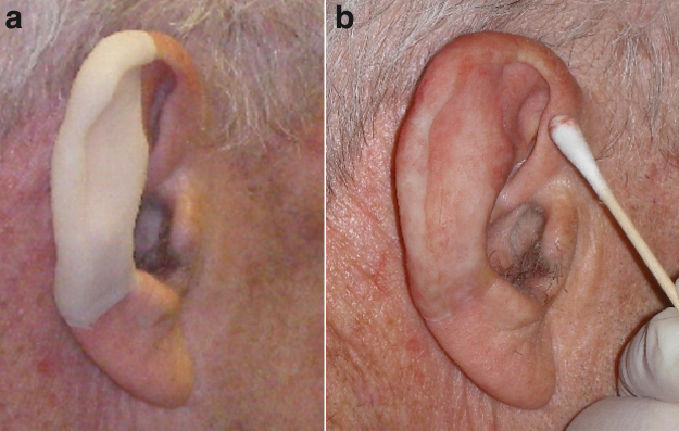
Maxillofacial prostheses (MFP) are an example of medical devices requiring flexible materials. Introduced in 1960, silicone prostheses exhibit an excellent combination of mechanical performance, chemical resistance, and stability5 (Fig. 1). They remain popular and have helped patients with acquired head and neck defects gain the confidence to return to their daily routine and social life.6 However, the construction of these patient-specific prostheses is expensive, laborious, and time-consuming.7 As such, a complete digital workflow to streamline the production of MFP is in high demand since the incorporation of a digital workflow has been shown to significantly reduce the processing time, required expertise, and cost.8,9 Most MFP digital workflows leverage indirect three-dimensional (3D) printing to create a mold for the 3D MFP net-shape without color information.
FIG. 1.
The silicone maxillofacial prosthesis fabricated in the conventional process. (a) The casted silicone ear prosthesis without colors. (b) The silicone ear prosthesis painted by an expert anaplastologist. Color images are available online.
Recent layerless silicone printing with continuous liquid interface production10 can be useful for MFP after resolving heterogenous distortion issues caused by anatomical asymmetry, but it is limited to a single-color material. This article is part of a research article series on developing mold-free, direct 3D printing of full color prostheses with the necessary mechanical, chemical, biological, and optical properties required for MFP.11
Among the many 3D printing technologies suitable for MFP manufacturing, droplet-based additive manufacturing has several significant advantages, such as multimaterial availability,12,13 voxel-level control over full color and texture,14,15 and easily separable support that does not damage the printed part's surface.16,17 However, the current commercially available materials for droplet-based technologies are designed for nonfunctional models, and do not meet the mechanical properties, surface finish, and biocompatibility requirements for MFP.
In addition, there are limitations to both the strategies and the newer investigative materials being developed for this application. For instance, facial prostheses fabricated using binder jetting technology, where starch powder is fused together with a water-based binder and subsequently infiltrated with silicone polymer, had mechanical properties and durability limitations because of the starch powder embedded throughout the silicone prosthesis.18 Studies using silicone powder-based approaches have had problems with poor resolution (1.54 mm droplet size) as well as challenges with printing simple geometric shapes.19 Flexible photoreactive polymers, such as urethane/acrylate, offer better mechanical properties and wear resistance, but their relatively low elongation at break20 and potential toxicity limit their potential for MFP applications.21
Direct inkjet deposition of silicone resins with high resolution remains a challenge due to the high viscosity of medical-grade silicone, which hinders stable droplet generation from printheads22 and may lead to poor layer deposition and a loss of fine details. However, a recent study developed ultraviolet curable silicone resins for droplet-on-demand 3D printing with 0.6 mm print resolution,23 but additional work is needed to eliminate the z-step lines.24
In this article, we investigate the direct 3D printing of MFP using customized silicone elastomer powder, produced by controlling the spray drying parameters. The resulting powders were used in a binder jetting 3D printing system to create geometrically complex green parts with enough green strength to survive postprocessing. After infiltration with silicone resin, those parts turned into a dense silicone composite material with an elongation at break and an elastic modulus comparable with that of conventional maxillofacial resins. Mechanical testing was performed to understand the influence of particle size, coating composition, surface treatment, and infusion conditions on the durability of the 3D-printed green part as well as the final silicone-infiltrated parts. In a subsequent report, we will detail the development of color inks that can be leveraged in this approach.
Materials and Methods
Binder preparation
The base 3D printing binder formulations used for 3D printing consisted of acetone (15 wt. %; Fisher Chemical, Pittsburgh, PA), high performance liquid chromatography (HPLC)-grade ethanol (30 wt. %; Sigma-Aldrich, St. Louis, MO), isopropyl alcohol (15 wt. %; Sigma-Aldrich), deionized (DI) water (38.9 wt. %), and polyvinylpyrrolidone (PVP, 1 wt. %, 10 kDa; Sigma-Aldrich). FD&C Red No. 40 powder pigment (0.1 wt. %; Colorcon, Irvine, CA) was added to the base solution. The solutions were prepared in a 50 mL conical tube and vortexed for 1 min to achieve a homogeneous mixture. The solution was filtered through a 0.2 μm polytetrafluoroethylene filter (Fisher Chemical) to eliminate any microparticles before loading it into the thermal inkjet printhead cartridges (HP11; Hewlett Packard, Inc., Palo Alto, CA).
Printhead preparation
A custom cleaning solution of acetone (5 wt. %) and Pluronic® F-68 surfactant (0.5 wt. %; Sigma-Aldrich) in DI water was prepared to clean the printhead cartridges. After opening the cartridge, the septum tube's connector and cap were temporarily removed to thoroughly rinse the inside of the cartridge. The cap and printhead cartridge were thoroughly washed with DI water for 1 min, and a custom cleaning solution for 1 min. The cartridge was then filled with the cleaning solution and a −0.1 bar vacuum was applied on the printhead nozzle for 10 min to remove any remaining pigment and contaminants with minimal damage on the printhead.
A washing solution was also prepared to clean the printhead nozzle during the self-purging sequence of the 3D printer (detailed below). The washing solution in the purge station was changed to a water-based solution with PVP (0.5 wt. %) and ethanol (30 wt. %), which flushed out possible contamination by the polymeric coating.
Powder preparation
Silicone powder mixture preparation for spray drying
Amorphous fumed silica-coated (3–7 wt. %), bis-vinyl dimethicone/dimethicone copolymer powder (Wrinkle Blur; MakingCosmetics, Inc., Snoqualmie, WA) with an average particle size of 2 μm and net density of 1.01 g/cm3 was used as the initial starting powder material. The silica-coated silicone powder was amino-silane treated with 3-aminopropyl(diethoxy)methylsilane (Sigma-Aldrich) to promote hydrogen bonding between silica and the binder (polyvinyl butyral, PVB).25
Briefly, silane solution of 97 wt. % ethanol, 1 wt. % DI water, and 2 wt. % silane was vortexed and left for 1 h for hydrolysis of silane. Sixty grams of the silica treated silicone powder was dispensed into a weighing dish and subsequently placed on a secondary stage within a tempered glass container. The silane solution (2 g) was added into the bottom of the glass container to avoid direct contact with the silicone powder (Fig. 2). The glass container was closed and purged with nitrogen to prevent unwanted reactions with oxygen, and incubated at 40°C for 24 h to promote the reaction between the silane vapor and the silica surface. To compare the effect of silanization on the mechanical properties and air volume of printed parts, one control group without silane surface treatment was also prepared.
FIG. 2.
(1) Starting powder is silica-coated silicone powder. (2) Vapor silane treatment was applied to introduce amine groups that can participate in hydrogen bonding with PVB. (3) Silane-treated silicone powder was mixed with PVB solution for spray drying. (4) PVB coating applied to the silicone powder via spray drying. (5) Final PVB-coated silicone powder. PVB, polyvinyl butyral. Color images are available online.
Various PVB solutions were formulated by dissolving Butvar®-76 powder (Eastman Chemical Ltd., Kingsport, TN) and Butvar-98 (Sigma-Aldrich) in a mixture of DI water and Reagent Alcohol (Fisher Chemical) at different ratios (Tables 1 and 2) at 60°C for 30 min in a closed flask. After complete dissolution, the mixture was removed from the heating source and silica-treated silicone powder was added to the mixture and dispersed using mechanical stirring for 20 min. The final mixture was stored in a closed poly bottle at room temperature.
Table 1.
Composition of Spray Drying Mixtures of Nonvolatile Ratio Control Group
| Nonvolatile ratio control | Ethanol (%) | Water (%) | SiO2-treated silicone (%) | B-98 (%) | B-76 (%) |
|---|---|---|---|---|---|
| Nonvolatile 5.00% | 85.00 | 10.00 | 4.38 | 0.31 | 0.31 |
| Nonvolatile 12.50% | 77.50 | 10.00 | 10.50 | 1.00 | 1.00 |
| Nonvolatile 16.00% | 74.00 | 10.00 | 14.00 | 1.00 | 1.00 |
| Nonvolatile 20.00% | 70.00 | 10.00 | 17.50 | 1.25 | 1.25 |
The polymer coating ratio, the ratio of sum of B-98 and B-76 among solid contents, was fixed to 16% in this group. The nonvolatile ratio control group was used to identify the relationship between particle size and characteristic of printed parts (Figs. 8a, d and 9a, d).
Table 2.
Composition of Spray Drying Mixtures of Polymer Coating Ratio Control Group
| PVB polymer coating ratio | Ethanol (%) | Water (%) | SiO2-treated silicone (%) | B-98 (%) | B-76 (%) |
|---|---|---|---|---|---|
| Polymer coating 8.00% | 77.50 | 10.00 | 11.50 | 0.50 | 0.50 |
| Polymer coating 12.00% | 77.50 | 10.00 | 11.00 | 0.75 | 0.75 |
| Polymer coating 16.00% | 77.50 | 10.00 | 10.50 | 1.00 | 1.00 |
| Polymer coating 20.00% | 77.50 | 10.00 | 10.00 | 1.25 | 1.25 |
Note that the nonvolatile ratio is fixed to 12.5% for all the samples in this group, and the polymer coating ratio, the ratio of sum of B-98 and B-76 among solid contents, was the main variable to control the property of spray drying mixture. Also, nonvolatile 12.50% and polymer coating 16.00% are identical.
PVB, polyvinyl butyral.
Spray drying of silicone powder mixture
The fluid mechanics of the spray drying mixture is important for controlling the spray-dried powder's morphology. Ohnesorge number (Oh) is a dimensionless ratio of the viscous forces to inertial and surface tension forces. These physical properties of the droplet during atomization is derived from surface tension (), viscosity (), density (), and the nozzle outlet diameter (d).26
| (1) |
Reynolds number (Re) is a dimensionless number that is frequently used in fluid mechanics to predict flow patterns in various fluid flow situations based on the physical properties of the atomized jet. It is derived from jet speed (U), viscosity (), density (), and the nozzle outlet diameter (d).26
| (2) |
To form stable droplets with spray drying, these two nondimensional numbers Oh and Re must be large enough to achieve an atomization regime.27 For spray drying jets in atomized regions, droplet size was controlled primarily by the Ohnesorge number. The volume mean diameter () of atomized droplets based on a nondimensional parameter was suggested as28:
| (3) |
where C1 and Cd are characteristic coefficients of the spray dryer, FR is Froude number describing speed/length ratio of jets, P is pressure, is the surface tension of water, and is the spray drying angle. The characteristic function, f1, is dependent on materials in the spray drying mixture28 and can be derived experimentally by spray drying the mixture and measuring the droplet size from the nozzle via image analysis taken with high-speed cameras.29 While this equation does not directly indicate the exact size of spray-dried powder, it suggests the possibility of controlling powder particle size based on the Ohnesorge number. For binder jetting, 31 μm was reported to be a suitable median particle size that balances between good packing density and surface roughness for green parts.30
The viscosity of the spray drying mixtures was measured using a rheometer (Discovery HR-2; TA Instruments, New Castle, DE) with a 40 mm 2.016° plate attachment and shear rate ranging from 25 to 630 Hz in a shear sweep method. Considering the shear thinning behavior and Reynolds number (≥2000) of the spray drying mixtures, average viscosity at 100 Hz was used to compare the viscosities of spray drying mixtures with different compositions. The surface tension was measured using the Ds/De pendant-drop method with the FTA125 goniometer (First Ten Angstroms, Portsmouth, VA) and calculated via image processing on a Java-based image processing program (ImageJ; NIH).
The powder mixtures were spray dried using a Mini Spray Dryer B-191 (BÜCHI Labortechnik AG, Flawil, Switzerland) and a 1.45-mm-sized nozzle. The powder mixture was fed into the droplet atomizer using tubing through a circulating peristaltic pump. Droplets of solution were sprayed through the nozzle into the drying chamber, where moisture was removed to leave solid particulate.
The resultant powders were collected via cyclone and deposited into the collection vessel, where the final usable powder was stored. Stiff polyethylene sheets were used to remove excess powders adhered to the interior walls of the drying and cyclone chambers. In instances of excessive powder adhesion to the borosilicate chambers, the collected powders were further filtered twice using a 500 and 100 μm sieve to restrict the powder particle size before use. The standard preset condition was used for the PVB powder mixture, which maintained the inlet temperature, sample feed rate, and compressed air flow rate at 65°C, 20%, and 600 L/h, respectively, at 90% vacuum aspiration.
To compare the effects of the polymeric coating ratio, samples with a fixed nonvolatile ratio of 12.5% and controlled PVB ratios of 8%, 12%, 16%, and 20% were tested. In this study, the nonvolatile ratio is defined as a weight ratio of the nonvolatile contents (PVB and silicone powder) among spray drying mixture. The fixed 16% polymer coating ratio with controlled nonvolatile ratio samples was also tested for particle size. Composition of spray drying mixture is shown in Tables 1 and 2.
To investigate whether the green strength of 3D-printed parts could be improved by the addition of extra PVB powder to the spray-dried powder, an additional sample group—noted as extra B98—was prepared. The B98 powder was filtered with a 100 μm mesh and mixed with the spray-dried silicone powder (16% PVB polymer coating ratio and 12.5% nonvolatile ratio) in a 1:4 weight ratio.
3D printing
A powder inkjet printer (ZPrinter-510; 3D Systems, Inc., Rock Hill, SC) was modified extensively to print silica-treated silicone powder. The power supply for the printhead board was separated to isolated 12 and 5 V power sources (TDK-Lambda Americas, National City, CA) to ensure a stable voltage supply during droplet generation. Fluid lines to waste trays were replaced with polytetrafluoroethylene tubing to prevent any possible damage or leaking of binder waste. Binder supply lines to printheads were disconnected to use printheads as cartridges to hold binder.
To minimize cross contamination of powders, the powder bed was supported by a customized, detachable building platform printed from photocurable acrylic resin (Vero; Stratasys, Inc., Eden Prairie, MN) with a polyjet printer (J750; Stratasys, Inc.). The custom-build platform snap-fitted precisely and had a perforated pattern that matched the original build platform of the Z510 printer.
To print, 3D models designed with CAD (Solidworks; Dassault Systemes, Vélizy-Villacoublay, France) and 3D design software (Zbrush; Pixologic, Los Angeles, CA) were loaded on the Z510 printer management program. The Z510 printer's build and feed platform were lowered to avoid interference. Then HP 11 printheads filled with the binder were installed on the fast axis assembly. The powder was set on the feed piston, and packed using a flat acrylic plate. The powder was spread by the roller in the fast axis and repeatedly built via the spreading function. A 0.1 mm layer thickness and 21.7% uniform binder saturation with monochromatic binder option was used for 3D printing.
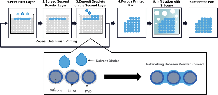
To build designed parts, the printer spread a single layer of powder and deposited a solvent-based binder to dissolve the PVB coating on the powder, which led to the connection between powder particles. This process was repeated until the last layer of the porous printed part was printed, as shown in Figure 3. The printed parts were dried in the 3D printer for 24 h to prevent cracking or warping. Unbound powder surrounding the printed parts was carefully removed in the postprocessing unit of the Z510 printer with an air gun (5 kPa pressure) and brush.
FIG. 3.
Binder jetting process. (1) The solvent binder droplet selectively dissolved PVB and formed networking between particles. (2) The silicone powder was spread over the first layer to form the second powder layer for printing. (3) Droplets were deposited onto the powder bed and formed the subsequent layer. (4) A porous 3D structure was formed by the PVB networking between particles. (5) The porous 3D structure was soaked in silicone resin. A sequential process of applying pressure followed by applying vacuum was used to fill the pores with silicone resin. (6) The final infiltrated part was removed from the remaining resin and became fully dense after curing of the silicone resin. 3D, three dimensional. Color images are available online.
The printed parts were porous (aka green parts) and required infiltration with silicone resins to form fully dense parts. The two parts of 20 A hardness platinum cure silicone (RTV 4420; Bluestar Silicones USA Corp., East Brunswick, NJ), and hexamethyldisiloxane (HMDS) solvent (Novocs Gloss; Smooth-On, Inc., Macungie, PA) were mixed at 75 wt. % and 25 wt. %, respectively. The ratio between part A and B of RTV 4420 was kept as 50 wt. %: 50 wt. % for all test conditions. The mixture was vortexed for 1 min to evenly mix the contents. The mixed silicone resin was carefully applied with a pipette to the surface of the green parts. Once the green parts were completely wet, they were submerged in a vat of the mixed silicone resin and placed in a zinc-plated pressurized tank (McMaster-Carr, Elmhurst, ILs).
Forced wetting conditions were created by applying pressure (3 bar) with compressed air for 30 min. After 30 min, the compressed air was slowly released (1 bar/min) to prevent stress generation due to the pressure change. The chamber was then connected to a vacuum (−0.7 bar) to further increase the infiltrated volume and remove the solvent. After 30 min, the chamber's release valve was slowly opened to restore the chamber pressure to atmospheric pressure (<1 bar/min). To investigate the effect of HMDS on the final part, an additional group was printed with the extra B-98 condition and infiltrated with silicone resin that had a 35 wt. % HMDS to 65 wt. % RTV 4420 ratio.
Mechanical testing
The elastic modulus of 10 (diameter) × 5 (height) (mm) cylindrical green (porous) parts before silicone infiltration was measured to evaluate the effects of print parameters and powder coating formulation on print quality. Due to the extremely low elastic modulus of the green parts, the samples were tested on an ultrasensitive Dynamic Mechanical Analyzer (DMA, Q800; TA Instruments) with a force resolution of 0.00001 N, strain resolution of 1 nm, and modulus precision ±1% under these conditions.
Four samples were tested for each polymer coating condition. The compression clamp and position of the DMA were calibrated before testing and every 2 h thereafter to ensure consistency. Samples were isothermally heated to 25°C with a 1 mN preloading and compressed at 20% compression/min to 60% compression. The stress at 40% compression was used to calculate the 40% compression modulus of each sample and was used for comparison between samples.
Tensile properties of infiltrated specimens (25 × 5 × 1 mm) were also measured using the DMA. The size of samples before testing was measured with a digital caliper (Ultra cal V; Fowler High Precision, Newton, MA). The samples were clamped by tensile testing jigs and secured using 0.25 N·m torque. The samples were isothermally heated to 25°C with a 1 mN preloading and elongated at 50% strain/min to 500% elongation. From the tensile tests, the samples' ultimate tensile strength, elongation at break, and 100% modulus were derived and compared.
Internal porosity
Microcomputed tomography (CT) was used to determine the internal porosity of the 3D-printed green samples [10 (diameter) × 5 (height) (mm) cylindrical shape] by measuring air volume inside the parts. The specimens were measured by Skyscan1176 MicroCT (Bruker micro-CT, Kontich, Belgium) using the following parameters: 900 ms exposure time, 40 kV voltage, 0.40° step angle, 4000 × 2672 resolution, and 9 μm per pixel size. From the microCT scan, two-dimensional cross-sectional bitmap images were obtained and visualized with NRecon (Micro Photonics, Inc., Allentown, PA), and combined to create a 3D model using Mimics (Materialise, Leuven, Belgium). To measure the air volume of the interior portion of the 3D-reconstructed model, a virtual disc [8 (diameter) × 4 (height) (mm)] control volume was used for the calculation using Boolean functions.
Morphology
Samples were observed with a Nova 230 Scanning Electron Microscope (SEM; FEI, Hillsboro, OR) to characterize spray-dried powder and printed parts. Particle sizes and aspect ratios of spray-dried powder were measured from SEM images (500 × ) using ImageJ. The surface characteristic, shape, and powder integration within both the green and infiltrated parts' structure were observed. Each of the solid samples was cut into 1-mm-thick slices using a razor blade and placed on the SEM stage with carbon conductive tape. Powder samples were gently placed on the carbon conductive tape on the SEM stage and excessive powder was removed with compressed air. The samples were observed in a low-vacuum detector, 50 Pa vacuum pressure, and water vapor condition.
Statistical analysis
Statistical analysis was conducted with GraphPad Prism software (GraphPad Software, Inc., San Diego, CA). Statistical significance was assessed using a one-way analysis of variance and a Student t-test for the analysis.
Results and Discussion
Characterization of spray drying mixture and spray-dried powder
In this article, we aimed to create novel silicone elastomer powders that can be used for the direct 3D printing of MFP. These powders were produced by applying PVB coatings under controlled spray drying conditions. The resulting polymer coating could then be dissolved by organic solvents in the binder. The final mechanical properties of parts fabricated by powder-based 3D printing are highly dependent on the properties of the powder used,31 and the morphology of the powder is controlled by the fluid mechanics of the spray drying mixture.32
Therefore, the fluid mechanics of the spray drying mixture used to prepare powders for powder-based 3D printing are important parameters that can be used to control the properties of the final 3D-printed parts. By leveraging this approach, we were able to use silicone powder in powder-based 3D printing. This was achieved by encapsulating the silicone powder in a polymer coating that is soluble in organic solvents, rather than aqueous solutions, and the parts created result in MFP with a higher resistance to moisture and humid environmental conditions.33
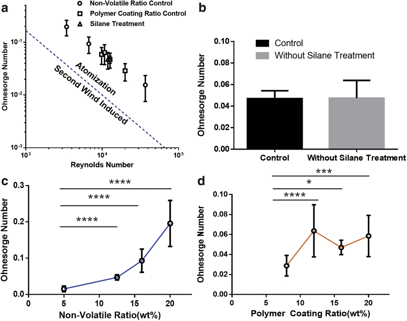
The results show that the Ohnesorge number was dominated by the nonvolatile and polymer coating ratios. To use the Ohnesorge number model to control the size of spray-dried powders, the spray drying mixture must satisfy the theoretical atomization condition for droplet formation. Figure 4a shows that after measuring the Reynolds and Ohnesorge numbers for each solution used in this study, the theoretical atomization condition was satisfied, and droplet formation did not involve a second wind-induced condition. This ensures that micron-sized droplets are formed.
FIG. 4.
Ohnesorge number model for optimized spray drying mixtures. (a) Ohnesorge number and Reynolds number analysis satisfied the atomization condition, confirming that the Ohnesorge number-based spray-dried powder approach was applicable to all mixtures used in this study. (b) Silane treatment resulted in no significant difference in the Ohnesorge number of the spray drying mixtures. (c) An increased nonvolatile ratio resulted in an increased Ohnesorge number (n = 4; mean ± SD; ****p < 0.0001). (d) The polymer coating control also showed a statistically significant difference when compared with the 8% polymer coating ratio (n = 4; mean ± SD; ****p < 0.0001; ***p < 0.001; *p < 0.1). SD, standard deviation. Color images are available online.
Next we wanted to confirm that silane treatment of the silicone powder did not negatively impact the atomization condition of the spray drying mixture. Figure 4b shows that amino silane treatment did not affect the Ohnesorge number (96.8% confidence level), which suggests that the shear resistance of the spray drying mixture is not affected by the silicone powder and PVB-ethanol solution interface. Rather, statistically significant increases in the Ohnesorge number with increasing nonvolatile ratios were observed (Fig. 4c).
In addition, the polymer coating ratio was shown to have a positive correlation to the Ohnesorge number with the higher polymer coating ratio samples having statistically greater Ohnesorge numbers when compared with the 8% polymer coating ratio sample (Fig. 4d). The nonvolatile ratio and polymer coating ratio are independent of each other and it is therefore possible to modulate the Ohnesorge number by changing each parameter individually. Thus, the Ohnesorge number-based droplet diameter model was applicable for PVB-silicone powder mixture and provides an effective way to control the morphology of custom 3D printing powders.
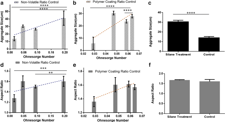
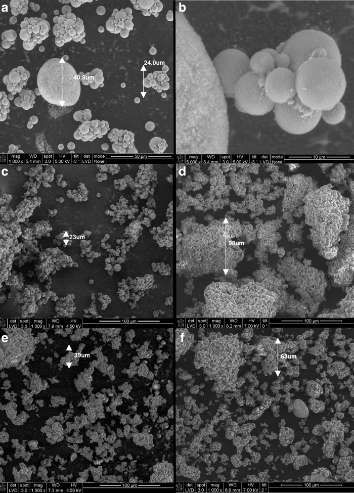
The morphology and aggregation of the resulting PVB-coated silicone particles were dependent on the Ohnesorge number of the spray drying mixture used for their preparation and whether the silicone particles had undergone amino silane treatment or not. As seen in Figure 5a, b, d, and e, the aggregate particle size and aspect ratio significantly increased with an increasing Ohnesorge number. Excessively large particles are easily formed in spray drying conditions with high Ohnesorge numbers, since large-sized atomized droplets form before the powder dries, causing agglomeration of dried powder (Fig. 6d).
FIG. 5.
Median (D50) particle size and morphology for spray-dried particle groups. (a–c) An increase in the Ohnesorge number resulted in an enlarged aggregated particle size in the nonvolatile ratio and polymer coating ratio control group. Silane treatment did not have an effect on the Ohnesorge number, but still caused a significant difference in particle size (n > 80; median ± SE; ****p < 0.0001). (d–f) The aspect ratio was significantly changed by the Ohnesorge number in the nonvolatile ratio and polymer coating ratio control group (n > 80; median ± SE; **p < 0.01; ***p < 0.001). No significant difference in aspect ratio was observed between the silane treatment conditions and the control group. SE, standard error. Color images are available online.
FIG. 6.
SEM images of spray-dried silica-treated silicone powders coated with PVB show aggregation due to the physical attraction between particles. (a, b) SEM images of silica-treated silicone powder without polymer coating for control group. The silicone particles were not heavily aggregated due to the lack of the binder at the silica surface. The samples had a 40.8 μm maximum aggregated particle size. (c) Nonvolatile ratio 5%. (d) Nonvolatile ratio 20%. (e) Polymer coating ratio 8%. (f) Polymer coating ratio 20%. SEM, scanning electron microscope.
Spray-dried powder with an Ohnesorge number condition below 0.1 (Fig. 6c, e, f) showed less aggregation in particles compared with Figure 6d. With the exception of the 5% and 20% nonvolatile ratio and the 8% polymer coating ratio groups, all the spray drying mixtures produced particle sizes within the size constraints (20–40 μm). The amino silane-treated groups also showed a significant increase in particle size, due to enhanced hydrogen bonding and adhesion strength between silica and PVB.25,34
Binder jetting technologies have lacked effective strategies to develop novel materials suitable for binder jetting 3D printing.35 The results presented here show the importance of the Ohnesorge number for controlling the spray-dried powder's size and morphology, which subsequently helps advance powder-based additive manufacturing by providing a strategy to expand the selection of suitable materials. The results also showed that silane treatment was an important parameter that influenced spray-dried particle size, independent of the fluid mechanical properties of the spray drying mixture. This approach is still in the early stages of development. Further research using advanced spray drying techniques, such as nanospray drying,36 may improve encapsulation and control particle size even more than the approach reported in this study.
Green part characterization
Adequate green strength is necessary for 3D-printed green parts to maintain their shape and withstand handling during postprocessing, and also directly contributes to the final part's mechanical properties. Particle size37 and binder ratio37 have been key parameters optimized in an effort to improve the mechanical properties of green parts. Both of these parameters impact the air volume within the green part, and a reduction in the air volume is directly correlated with an improvement in the part's mechanical properties.38 Here, we controlled the powder packing and the mechanical strength of green parts by fabricating polymer-coated powders with tunable particle sizes and polymer coating ratios.39
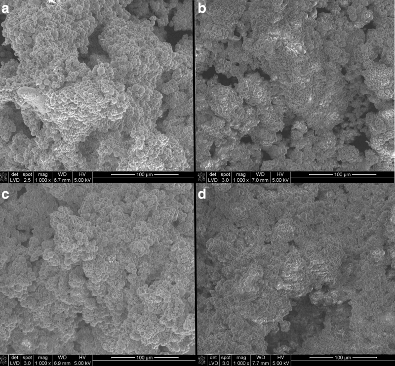
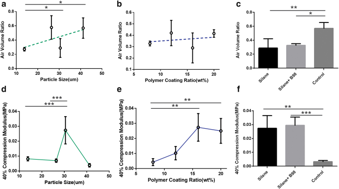
The compressive strength and air volume of the 3D-printed green parts were dominated by particle size and polymer coating ratio. SEM micrographs of the green parts showed a porous structure with binding between silica-treated silicone powder by PVB (Fig. 7a–d). These results show that the organic solvent-based binder was able to dissolve the PVB coating, which subsequently bounded spray-dried silicone powder together. MicroCT scans of the resulting green parts found that increasing the particle size increased the air volume (Fig. 8a). Similarly, increasing the polymer coating ratio also increased the air volume (Fig. 8b). The compressive strength of the green part decreased as particle aggregation increased with the exception of the 30.5 μm particle group (Fig. 8d).
FIG. 7.
SEM images of 3D-printed porous structures. Networking between the silicone particles can be observed, which is formed by the printed binder dissolving the PVB coating on the silicone particles and subsequently evaporating and leaving behind a solid PVB network. (a) Nonvolatile ratio 5%. (b) Nonvolatile ratio 20%. (c) Polymer coating ratio 8%. (d) Polymer coating ratio 20%.
FIG. 8.
Air volume and green strength for the 3D-printed porous structure. (a–c) The air volume of the green parts, determined via microCT, reveals a positive correlation between particle size (nonvolatile ratio group) and the polymer coating ratio. In addition, the green parts printed with control powder (nonsilane treated) had a larger air volume within the structure than the green parts printed with the silane and silane+B98 groups (n = 4; mean ± SD; **p < 0.01; *p < 0.1). (d–f) The green strength, reported as 40% compression modulus, showed a maximum mean value when the median particle size was 30.5 μm. As the polymer coating ratio increased, the green strength also significantly increased, despite the decrease in packing density as evidenced by the greater air volume in green parts with higher polymer coating ratios. In addition, the green strength of the parts printed with the nonsilane-treated powder was significantly lower than the green strength of the parts printed with silane-treated powder (n = 4; mean ± SD; ***p < 0.001; **p < 0.01; *p < 0.1). CT, computed tomography. Color images are available online.
The increased polymer coating ratio improved the compressional strength (Fig. 8e). Adding extra PVB powder with the spray-dried powder did not significantly impact the air volume or the green strength of the resulting 3D-printed structure (Fig. 8c, f). In contrast, the control (nonsilane-treated) samples had a significant decrease in green strength and an increase in air volume when compared with the silane-treated groups. This highlights the importance of the hydrogen bonding between PVB and the silicone powder, made possible by amino silane treatment, in creating green parts that are strong enough to survive postprocessing. Such strategies that promote the interfacial bonding between the binding agent and the powder can be leveraged for the development of future binder jetting-compatible powders composed of other hard-to-print materials.
Previous studies have identified the air volume of 3D-printed green parts, determined by particle size and morphology, as the main factors affecting the integrity and quality of binder jetted parts.35 Briefly, decreased contact area between particles amounts to greater air volume in the green part, which translates to less structure support and lowered green strength.40 There are limits to how much green strength can be increased by reducing air volume when printing with uncoated powders by simply changing the packing density.
Models using 35-μm-sized spheres showed that the lowest possible air volume was 36%.41,42 Because the PVB coating ultimately provides the polymer network that holds particles together, the results demonstrate that the polymer coating ratio also has a significant influence on the strength of the resulting green parts when polymer-coated powders are used in binder jetting applications. In this study, particle size was controlled by changing the Ohnesorge number by way of the nonvolatile ratio.
The greatest green strength was observed when the median polymer-coated silicone powder size was 30.5 μm (27.4 ± 9.1 kPa), which was prepared using the nonvolatile 12.5% ratio group. Particle sizes both above and below this value produced green parts with significantly lower strength even though air volumes as low as 27.1% were achieved in green parts printed with 13.8 μm polymer-coated silicone powders.
In general, however, there was a decrease in green strength as the particle size and, by extension, air volume increased. These results are in general agreement with the 20 μm or greater particle size guidelines43 used for metal powders and are applicable to binder jetting silicone powder. When the 30.5 μm powders were coated with different ratios of polymer (Fig. 8e), the results show that decreasing the polymer coating ratio below 15 wt. % led to significant decreases in the compressive strength of the green parts. However, further increasing the polymer coating ratio results in no significant change in the green strength. Therefore, there is a limit to how much additional green strength can be increased via polymer coating ratio alone and a ceiling on how much air volume can be tolerated even with the increased polymer binder.
Infiltrated part characterization
The materials used for MFP must be durable because MFP have thin margins to seamlessly blend the prosthesis with the surrounding facial tissue.44 While movement of the facial muscles may only cause 10% strain on prostheses, previous studies have reported that the ideal material for facial prostheses should be able to withstand 400–800% strain before breaking.45 For example, the widely used commercial prostheses material, MDX-4-4210, showed a 394.3% elongation at break.46
Furthermore, materials for MFP should have stiffnesses comparable with the facial tissues they are replacing. This ensures that any contortion of the patient's face is transferred to the MFP. As such, the typical elastic modulus of MFP materials is in the range of 0.2–2.1 MPa.45 To satisfy these material requirements, the 3D-printed green parts were infiltrated with curable silicone elastomer to create fully dense parts. These infiltrated parts underwent mechanical testing and were qualitatively examined using SEM.
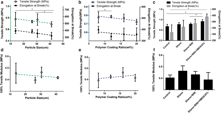
The results showed the parameters that improved the strength of the green parts had a negative impact on the final properties of the infiltrated parts. Increasing the powder size used during the printing process negatively affected the elongation at break and tensile strength of the final infiltrated parts (Fig. 9a). These results highlight the importance of identifying the proper particle size for 3D printing with silicone powder.
FIG. 9.
Mechanical properties of silicone infiltrated structures. (a) Effect of particle size versus tensile strength. (b) Effect of polymer coating ratio versus tensile strength. (c) Silane treatment effect on tensile strength and elongation at break. Improvements in tensile strength and elongation at break were observed with a decreasing particle size. Increases in the polymer coating ratio hindered the elongation at break and the tensile strength of the samples tested. The silane treatment enhanced the tensile strength and elongation at break of the samples when compared with the control group. The 35% HMDS group showed the best results, showing improvement over the results of the silane+B98 samples (n = 4; mean ± SD; *p < 0.1). (d) Effect of particle size versus 100% tensile modulus. (e) Effect of polymer coating ratio versus 100% tensile modulus. (f) Silane treatment effect on 100% tensile modulus. The 100% tensile modulus was decreased in samples with larger particle sizes and smaller polymer ratio coating conditions. There was no significant difference observed in the tensile modulus in the silane and additive conditions (n = 4; mean ± SD; *p < 0.1). HMDS, hexamethyldisiloxane. Color images are available online.
Interestingly, increasing the polymer coating ratio, which helped improve the strength of the green parts (Fig. 8e) so that they could survive postprocessing procedures, resulted in a decrease in both the tensile strength and elongation at break of the final parts (Fig. 9b). This is likely due to the fact that PVB is not as flexible as the curable silicone resin used to infiltrate the final part (RTV 4420). The manufacturer reported that RTV 4420 can withstand 500% strain before breaking,47 while PVB can only withstand between 100% and 120% strain before breaking.48 However, the highest elongation at break achieved in this study (440%) was from the extra B-98 + 35% HMDS group (Fig. 9c). The increase in PVB content of this group is likely countered by the improved infiltration of the silicone caused by HMDS dilution. The addition of HMDS lowered the viscosity of the silicone resin mixture, which eased resin infiltration into the pores of the green parts by lowering the shear resistance of the silicone resin and accelerating the speed of wetting.49,50
All groups had an elastic modulus that fell within the range typical for prostheses using shore 20 A curable silicone as the infiltrate material.45 As seen in Figure 9d–f, the elastic modulus for each group studied was between 0.39 and 0.46 MPa. Studies have reported the ideal hardness for facial prostheses to be within the range of 25 to 55 A51 and that a linear relationship between hardness and elastic modulus of elastomeric silicone exists.52 For instance, the shore 30.3 A prosthetic silicone has an elastic modulus of 0.345 MPa, while the shore 44.3 A version has a value of 0.794 MPa.51 In this study, stiffnesses comparable with skin were achieved by infiltrating 3D-printed parts made with a soft silicone resin. The results showed an increase in the 100% tensile modulus with decreasing particle size and increasing polymer coating ratios (Fig. 9d, e).
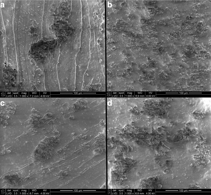
Furthermore, no significant cracks or voids were seen in the infiltrated structures under SEM (Fig. 10). This is in contrast to previously reported infiltrated structures made with starch-silicone, which had undergone a similar 3 bar pressure infiltration process, and broke after only 244% elongation strain.53 Overall, these results show that there are several parameters that can be adjusted to achieve the desired mechanical properties of 3D-printed MFP fabricated with PVB-coated silicone powders and infiltrated with curable silicone resin.
FIG. 10.
SEM images of silicone infiltrated structures. Silicone particles were embedded within the silicone resin and no significant cracks or voids were observed. This shows that the silicone resin filled the pores of the green parts and was successfully integrated into the main structure using the pressure-vacuum processing sequence. (a) Nonvolatile ratio 5%. (b) Nonvolatile ratio 20%. (c) Polymer coating ratio 8%. (d) Polymer coating ratio 20%.
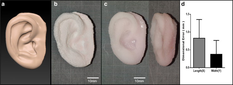
As a proof-of-concept, a prosthetic ear was fabricated via binder jetting using the PVB-coated silicone powders prepared in this study and underwent postprocessing (i.e., infiltration with silicone resin using the pressure-vacuum sequence). Specifically, we wanted to confirm that complex geometrical structures with fine details could be 3D printed with the spray-dried powder and survive postprocessing. As seen in Figure 11, the 3D-printed structure (Fig. 11b) maintained the contours of the digital model (Fig. 11a). This structure further survived the infiltration process using silicone resin that had been diluted with 35% HMDS (Fig. 11c).
FIG. 11.
Proof-of-concept prosthetic ear with complex details. Designed helix and antihelix profiles were printed as intended. The printing time was 3 h and the infiltration process took 1 h. Adding in drying and curing times, this approach can be easily adapted to the clinic, with a delivery time to the patient of ≤2 days. (a) 3D model of ear-shaped structure. (b) Noninfiltrated porous prosthesis. (c) Silicone infiltrated prosthesis. No noticeable step lines were observed, which may allow for the direct 3D printing of detailed prostheses that require minimal touch up, such as polishing or coating. (d) x- and y-dimensional accuracy of rectangular samples. Parts shown were infiltrated with silicone resin that had been diluted (i.e., 35% HMDS). Color images are available online.
To quantify the mean dimensional error, 3D-printed rectangular samples (25 × 5 × 1 mm) were fabricated, and differences in the x- and y-dimensions were measured. As seen in Figure 11d, the printed structures had a mean dimensional error of 0.38 mm in the y-direction and 0.83 mm in the x-direction—demonstrating that this approach is highly accurate. These promising results open the door to using this approach to fabricate other highly complex features needed for facial prostheses.
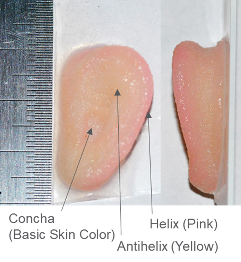
Furthermore, the monochromatic prosthetic ear printed for this article serves as the foundation for future innovation involving the full-color 3D printing of MFP (Fig. 12). By using color inkjet printheads during the printing process, a full cyan-yellow-magenta-clear (CYMC) color space for realistic 3D-printed parts can be achieved. The part's color can be precisely defined by controlling the droplet deposition from each printhead.54 Thus, this novel powder system serves as a catalyst for the development of proper CYMC binders, which will help make a fully digital workflow for colored MFP that require minimal human intervention a reality.
FIG. 12.
Full color 3D-printed prosthetic ear using silicone powder. Each marked location was virtually colored with the noted color to mimic the shade and color distribution of the ear. An array of multiple printheads were used for the full color 3D printing, with each printhead dispensing a different colored binder. The graduation line on the ruler depicted in the picture corresponds to 0.5 mm. Color images are available online.
Conclusion
In this study, we explored the combination of PVB-coated silicone powder and a customized binder jetting process as a fabrication method for the direct 3D printing of MFP. By utilizing an Ohnesorge number-based approach for the spray drying process, control over the spray-dried powder morphology was possible, which directly impacted the strength of the resulting 3D-printed parts. Parameters such as polymer coating ratio, particle size, and silane treatment of the silicone powder all significantly affected the mechanical properties of the 3D-printed green parts and infiltration by the silicone resin. The combination of silane treatment and the dilution of the silicone resin with HMDS resulted in a highly flexible final part that could withstand 440% strain before breaking as well as satisfy the stiffness requirements of MFP.
Overall, this study demonstrates the potential to directly print net shape MFP from customized silicone powder. Ongoing efforts involving colored-binders are aimed at developing a fully digital workflow for the direct 3D printing of silicone MFP with color gradients over a range of human skin tones. Future publications will evaluate the biocompatibility of these prostheses, and the color stability of directly printed color gradients under accelerated weathering and aging.
Acknowledgments
Parts of this work have been submitted by Yun Chang Lee, in partial fulfillment of the requirements for a Doctor of Philosophy degree, at the University of California, Los Angeles (UCLA). The repurpose of the data for publication was allowed in agreement with UCLA. The authors thank Dr. Jay Jayanetti, Associate Program Director of the UCLA Maxillofacial Prosthetic Fellowship Program, for clinical insights, and Ms. Tomomi Baba for valuable laboratory assistance.
Author Disclosure Statement
There is no conflict of interest.
Funding Information
This research is funded by Weintraub Family Foundation, Johnny Carson Foundation, Shapiro Family Charitable Foundation, Stephen and Mary Birch Foundation, and Various Donors to the Weintraub Center and Innovative Digital Dentistry Systems.
References
- 1. Rengier F, Mehndiratta A, Von Tengg-Kobligk H, et al. . 3D printing based on imaging data: review of medical applications. Int J Comput Assist Radiol Surg 2010;5:335–341. [DOI] [PubMed] [Google Scholar]
- 2. Morrison RJ, Hollister SJ, Niedner MF, et al. . Mitigation of tracheobronchomalacia with 3D-printed personalized medical devices in pediatric patients. Sci Transl Med 2015;7:285ra64. [DOI] [PMC free article] [PubMed] [Google Scholar]
- 3. Truby RL, Lewis JA. Printing soft matter in three dimensions. Nature 2016;540:371. [DOI] [PubMed] [Google Scholar]
- 4. Majidi C. Soft robotics: a perspective—current trends and prospects for the future. Soft Robot 2014;1:5–11. [Google Scholar]
- 5. Barnhardt G. A new material and technique in the art of somato-prostheses. J Dent Res 1900;39:830. [DOI] [PubMed] [Google Scholar]
- 6. Mitra A, Choudhary S, Garg H, et al. . Maxillofacial prosthetic materials-an inclination towards silicones. J Clin Diagn Res 2014;8:ZE08. [DOI] [PMC free article] [PubMed] [Google Scholar]
- 7. He Y, Xue G-H, Fu J-Z. Fabrication of low cost soft tissue prostheses with the desktop 3D printer. Sci Rep 2014;4:6973. [DOI] [PMC free article] [PubMed] [Google Scholar]
- 8. Bibb R, Eggbeer D, Evans P. Rapid prototyping technologies in soft tissue facial prosthetics: current state of the art. Rapid Prototyp J 2010;16:130–137. [Google Scholar]
- 9. Mohammed MI, Cadd B, Peart G, et al. . Augmented patient-specific facial prosthesis production using medical imaging modelling and 3D printing technologies for improved patient outcomes. Virtual Phys Prototyp 2018;13:164–176. [Google Scholar]
- 10. Samulski ET, Ermoshkin A, Gutierrez C, et al. Continuous liquid interface production with sequential patterned exposure. 2018, Google Patents. [Google Scholar]
- 11. Ross MT, Cruz R, Hutchinson C, et al. . Aesthetic reconstruction of microtia: a review of current techniques and new 3D printing approaches. Virtual Phys Prototyp 2018;13:117–130. [Google Scholar]
- 12. Mohammed MI, Tatineni J, Cadd B, et al. Advanced auricular prosthesis development by 3D modelling and multi-material printing. In: DesTech 2016: Proceedings of the International Conference on Design and Technology, Knowledge E, Geelong, Australia, 2017. [Google Scholar]
- 13. Bailey A, Merriman A, Elliott A, et al. Preliminary testing of nanoparticle effectiveness in binder jetting applications. In: 27th Annual International Solid Freeform Fabrication Symposium, Austin, TX, 2016. [Google Scholar]
- 14. Brunton A, Arikan CA, Urban P. Pushing the limits of 3D color printing: error diffusion with translucent materials. ACM Trans Graph 2015;35:4. [Google Scholar]
- 15. Bader C, Kolb D, Weaver JC, et al. . Data-driven material modeling with functional advection for 3D printing of materially heterogeneous objects. 3D Print Addit Manuf 2016;3:71–79. [Google Scholar]
- 16. Napadensky E. Inkjet 3D printing. In: Magdassi Shlomo, ed. 1954: The Chemistry of Inkjet Inks. New Jersey, London: World Scientific, 2010; pp. 255–267. [Google Scholar]
- 17. Salmi M, Ituarte IF, Chekurov S, et al. . Effect of build orientation in 3D printing production for material extrusion, material jetting, binder jetting, sheet object lamination, vat photopolymerisation, and powder bed fusion. Int J Collab Enterp 2016;5:218–231. [Google Scholar]
- 18. Zardawi FM. Characterisation of Implant Supported Soft Tissue Prostheses Produced with 3D Colour Printing Technology. Sheffield, United Kingdom: University of Sheffield, 2013. [Google Scholar]
- 19. Liravi F, Vlasea M. Powder bed binder jetting additive manufacturing of silicone structures. Addit Manuf 2018;21:112–124. [DOI] [PMC free article] [PubMed] [Google Scholar]
- 20. Yap Y, Dikshit V, Lionar SP, et al. Investigation of fiber reinforced composite using multi-material 3D printing. In: Annual International Solid Freeform Fabrication Symposium, Austin, TX, 2016. [Google Scholar]
- 21. Walsh ME, Ostrinskaya A, Sorensen MT, et al. . 3D-printable materials for microbial liquid culture. 3D Print Addit Manuf 2016;3:113–118. [Google Scholar]
- 22. Liravi F, Toyserkani E. A hybrid additive manufacturing method for the fabrication of silicone bio-structures: 3D printing optimization and surface characterization. Mater Des 2018;138:46–61. [Google Scholar]
- 23. Grunewald SJ. Wacker announces new silicone 3D printing technology. In: 3D Printing Materials. 3D Print.com, 2015. https://3dprint.com/88316/wacker-3d-printed-silicone/ (last accessed July 15, 2021).
- 24. Unkovskiy A, Spintzyk S, Brom J, et al. . Direct 3D printing of silicone facial prostheses: a preliminary experience in digital workflow. J Prosthet Dent 2018;120:303–308. [DOI] [PubMed] [Google Scholar]
- 25. Miller A, Berg J. Effect of silane coupling agent adsorbate structure on adhesion performance with a polymeric matrix. Compos A Appl Sci Manuf 2003;34:327–332. [Google Scholar]
- 26. Hutchings IM, Martin GD. Inkjet Technology for Digital Fabrication. Hoboken, New Jersey, United States: John Wiley & Sons, 2012. [Google Scholar]
- 27. Reitz RD. Atomization and other breakup regimes of a liquid jet. PhD Thesis 1375-T, NJ, USA: Princeton University, 1978. [Google Scholar]
- 28. Post SL, Hewitt AJ. Flat-fan spray atomization model. Transactions of the ASABE 2018;61:1249–1256. [Google Scholar]
- 29. Pawar SK, Henrikson F, Finotello G, et al. . An experimental study of droplet-particle collisions. Powder Technol 2016;300:157–163. [Google Scholar]
- 30. Miyanaji H. Binder jetting additive manufacturing process fundamentals and the resultant influences on part quality. Electronic Theses and Dissertations, Paper 3058, University of Louisville, 2018. [Google Scholar]
- 31. Huang S, Ye C. Preparation and performance of binder jetting porous alumina ceramic. IOP Conf Ser Mater Sci Eng 2020;770:012057. [Google Scholar]
- 32. Heinzen C, Berger A, Marison I. Use of vibration technology for jet break-up for encapsulation of cells and liquids in monodisperse microcapsules. In: Nedovic V, Willaert R, eds. Fundamentals of Cell Immobilisation Biotechnology. Kluwer Academic Publishers, 2004; pp. 257–275. [Google Scholar]
- 33. Bora PJ, Azeem I, Vinoy KJ, et al. . Morphology controllable microwave absorption property of polyvinylbutyral (PVB)-MnO2 nanocomposites. Compos B Eng 2018;132:188–196. [Google Scholar]
- 34. Wu G, Liu C, Lu C, et al. . Lipophilic modification of T-ZnOw and optical properties of T-ZnOw/PVB composite films. Appl Phys A 2020;126:1–10. [Google Scholar]
- 35. Jimenez EM, Ding D, Su L, et al. . Parametric analysis to quantify process input influence on the printed densities of binder jetted alumina ceramics. Addit Manuf 2019;30:100864. [Google Scholar]
- 36. Li X, Anton N, Arpagaus C, et al. . Nanoparticles by spray drying using innovative new technology: the Büchi Nano Spray Dryer B-90. J Control Release 2010;147:304–310. [DOI] [PubMed] [Google Scholar]
- 37. Shrestha S, Manogharan G. Optimization of binder jetting using Taguchi method. JOM 2017;69:491–497. [Google Scholar]
- 38. Bai Y, Wagner G, Williams CB. Effect of particle size distribution on powder packing and sintering in binder jetting additive manufacturing of metals. J Manuf Sci Eng 2017;139:081019. [Google Scholar]
- 39. Bai Y, Wagner G, Williams CB. Effect of bimodal powder mixture on powder packing density and sintered density in binder jetting of metals. In: 2015. Annual International Solid Freeform Fabrication Symposium, Austin, Texas, 2015. [Google Scholar]
- 40. Moon I-H, Choi J-S. Dependence of green strength on contact area between powder particles for spherical copper powder compacts. Powder Metall 1985;28:21–26. [Google Scholar]
- 41. Elliott AM, Momen AM, Benedict M, Kiggans J. Experimental study of the maximum resolution and packing density achievable in sintered and non-sintered binder-jet 3D printed steel microchannels. In: ASME International Mechanical Engineering Congress and Exposition. American Society of Mechanical Engineers, Houston, TX, 2015. [Google Scholar]
- 42. Deprez K, Vandenberghe S, Van Audenhaege K, Van Vaerenbergh J, Van Holen R. Rapid additive manufacturing of MR compatible multipinhole collimators with selective laser melting of tungsten powder. Med Phys 2013;40:012501. [DOI] [PubMed] [Google Scholar]
- 43. Sachs EM. Powder dispensing apparatus using vibration. 2000, Google Patents. [Google Scholar]
- 44. Hatamleh MM, Watts DC. Mechanical properties and bonding of maxillofacial silicone elastomers. Dent Mater 2010;26:185–191. [DOI] [PubMed] [Google Scholar]
- 45. Lewis D, Castleberry D. An assessment of recent advances in external maxillofacial materials. J Prosthet Dent 1980;43:426–432. [DOI] [PubMed] [Google Scholar]
- 46. Montgomery PC, Kiat-Amnuay S. Survey of currently used materials for fabrication of extraoral maxillofacial prostheses in North America, Europe, Asia, and Australia. J Prosthodont 2010;19:482–490. [DOI] [PubMed] [Google Scholar]
- 47. Blue Star SILBIONE® RTV 4420 A/B. Bluestar Silicones, East Brunswick, NJ, United States: SILBIONE, 2012 (last accessed August 15, 2018). [Google Scholar]
- 48. Carrot C, Bendaoud A, Pillon C, et al. Polyvinyl butyral. In: Olabisi O, Adewale K, eds. Handbook of Thermoplastics, red. Boca Raton, Florida, USA: CRC Press, 2016; pp. 89–138. [Google Scholar]
- 49. Lei YY, Zheng G, Sun Y, et al. Study on preparation and factors of amino silicone with low viscosity. In: Chen X, ed. Advanced Materials Research. Baech, Switzerland: Trans Tech Publications, 2011; pp. 2449–2453. [Google Scholar]
- 50. Blake T, Shikhmurzaev Y. Dynamic wetting by liquids of different viscosity. J Colloid Interface Sci 2002;253:196–202. [DOI] [PubMed] [Google Scholar]
- 51. Wolfaardt JF, Chandler HD, Smith BA. Mechanical properties of a new facial prosthetic material. J Prosthet Dent 1985;53:228–234. [DOI] [PubMed] [Google Scholar]
- 52. Meththananda IM, Parker S, Patel MP, et al. . The relationship between Shore hardness of elastomeric dental materials and Young's modulus. Dent Mater 2009;25:956–959. [DOI] [PubMed] [Google Scholar]
- 53. Zardawi FM, Xiao K, Van Noort R, et al. . Investigation of elastomer infiltration into 3D printed facial soft tissue prostheses. Anaplastology 2015;4:1. [Google Scholar]
- 54. Chen G, Chen C, Yu Z, et al. Color 3D printing: theory, method, and application. In: Shishkovsky I, ed. New Trends in 3D Printing. London, UK: InTechOpen, 2016; pp. 25–51. [Google Scholar]


