

Abstract

We used the phase-field model of the existing Nonsolvent Induced Phase Separation (NIPS) method to add the variable of temperature in simulating the changes in the process of membrane formation. The polyvinylidene fluoride (PVDF) membrane system was applied to examine the influence of coagulation bath temperature change on the skin-sublayer of the membrane structure, thereby elucidating the development process of membrane structure under different conditions and shedding light on the most suitable coagulation bath temperature ranges. It was found that as coagulation bath temperature increased, the number of interface pores in the outer skin layer decreased, but the size increased. As a result, it changed from the crack shape to round-hole shape, thus making the pore structure looser. In the sublayer, the mesh support structure was increased, which enhanced the mechanical strength of the membrane. Relevant experiments also verify the effectiveness of the model.
1. Introduction
The immersion precipitation phase transformation method (NIPS) represents a simple preparation method for polymer membrane materials, by which the changes in membrane properties and structure can be achieved by changing the film-forming conditions. The shape of membrane pores can be roughly divided into dense nonporous, sponge-like, and finger-like pores.1−4 Polyvinylidene fluoride (PVDF) is a highly nonreactive thermoplastic fluoro-polymer, characterized by high mechanical strength, acid and alkali resistance, and good chemical stability. Most importantly, PVDF stands out with an excellent dielectric, is biocompatible, and has high separation accuracy and high efficiency.5−8 Due to this, it has attracted considerable attention of researchers focused on membrane separation. To obtain PVDF membranes with different separation properties and to perform the separation efficiently, the membrane structure and the shape of membrane pores are often modified by changing the concentration of casting solution, additives, composition, and temperature of coagulation.9−11 As a PVDF-based polymer is characterized by a certain regularity, when the casting liquid temperature is lower than the melting point of the polymer, it can be immersed in a coagulation bath. This would subsequently trigger the crystallization of the polymer from solution to the polymer-rich phase and polymer-poor phase, thereby weakening the mixed free energy. The influence of the temperature and composition of the coagulation bath on the size and shape of the membrane pores is also affected by the effects of the dense cortex and sublayer. The skin layer is generally used as a selective layer with a thickness of 0.1–1 μm, which mainly plays a role in retention. The sublayer structure plays a supporting role and requires mechanical strength, while maintaining a high membrane flux. Therefore, it is necessary to study the structural changes in the cortex and sublayer caused by the changes in coagulation bath temperature. However, the variability of temperature fundamentally plagues the efficient coagulation bath temperature range through the experimental method. Moreover, given the heat transfer process, it is challenging to carry out in situ observation, and experimental characterization is, therefore, limited.
The thermodynamic theory of Flory–Huggins indicated that numerous dynamic models, including macroscopic scale transfer model, microcosmic scale phase-field theory, and microscopic scale molecular/particle-based simulation method can be adopted. To date, multiple experimental and simulation studies on the phase separation process and simulated structure were performed for different control factors in the film-forming process. The earliest works on the NIPS model concerned a one-dimensional steady-state diffusion model, developed by Cohen12 in 1979. In 1988, McHugh et al.13,14 constructed a pseudo-two-component model based on the phase separation behavior of polymer/solvent/nonsolvent ternary system. Furthermore, Cheng et al.15 benefited from the experience of the previous models and demonstrated that a variety of membrane structures such as the formation of the surface dense layer, homogeneous and porous, can be numerically predicted. By 2017, the strict kinetic model, established by Khansary et al.,16 yielded the control equations of concentrated phase and lean phase, respectively, for the liquid phase of a cast membrane. In this way, the phase separation trajectory could enter the vitrification region in the phase diagram. By 2022, Irish Valerie Maggay et al.17 proved that water as an additive can effectively inhibit the formation of macropores by using 2-pyridone to prepare skin free polysulfone membranes. Later, Luyao Zhang et al.18 systematically studied the effects of pore forming agents and additives in poly isophthalamide ultrafiltration membrane on the membrane structure and performance using density functional theory, and proved the interaction energy between components. However, the existing models did not consider the influence of coagulation bath temperature. Given the exposure of macro-molecular dynamics to the temperature effects, it is necessary to study the process of temperature on the formation of membrane pore structures.
As an ultrafiltration membrane and microfiltration membrane, the PVDF membrane plays an important role in the treatment of macromolecules, bacteria, sediment, and other impurities in water. PVDF membrane includes nonporous dense cortex and porous, whereas its asymmetric structure is easy to identify.
This study used the above-mentioned model to integrate the variable of temperature into the PVDF membrane system for phase-field optimization. As a result, the effect of temperature in the whole phase conversion process was simulated in this study. The main aim of the study was to examine the influence of coagulation bath temperature change on the skin–sublayer of the membrane structure, thereby elucidating the development process of membrane structure under different conditions and shedding light on the most suitable coagulation bath temperature ranges. The ternary Cahn-Hillard equation and Flory–Huggins thermodynamic theory were applied without considering the cross-phase, which exerts a minor effect on the system, according to the polymer macro-molecular dynamics theory.19,20 Phillies’21,22 experimental model was applied to establish the change of each component single molecule in pure water due to temperature change. As the initial volume fraction of solute substantially affects the formation of cortex and sublayer, its experimental observations were hampered. In the process of preparing the PVDF membrane by the NIPS method, we fixed the volume fraction of PVDF to 18%, added the variable of temperature for further simulation, and compared the experimental results with the final simulations to evaluate the effectiveness of the model. A ternary phase diagram23−25 was constructed to illustrate the results of our analysis.
Due to the inherent limitations and the unpredictability of thermodynamic and kinetic factors in the whole PVDF membrane system, it is difficult to quantify the difference caused by temperature change by the experimental method, which can only be overcome by the simulation method. In the experimental stage, we opted for PVDF/DMF/H2O as the polymer/solvent/nonsolvent system and use the single variable method for the preparation of the membrane. Under different PVDF volume fractions, when the temperature changed from 273.15 K to 353.15 K, we analyzed the change of its diffusion behavior and verified the correctness of the model with the experimental results. We revealed a difference in PVDF membrane structure in the final morphology at different temperatures.
2. Model
The phase-field method is fundamentally based on the Ginzburg–Landau26 theory. In particular, it uses differential equations to reflect the diffusion with a specific physical mechanism, the change of chemical potential, and the change process of the thermodynamic driving force. The development of the phase-field model was started in the 1950s and was actively continued through the 1970s.27−29 Cahn, Hillard, and Allen have proposed the nonzero thickness diffusion between separated phases based on the work involving spin decomposition dynamics. In our study, we applied the phase-field method to the nonsolvent/solvent/polymer ternary system during immersion precipitation.
Considering the Cahn Hillard equation and the assumption that the volume fraction as the conservation constant, we simulated the submerged precipitation process. The general Cahn-Hillard equation eq 1 can be formalized as
| 1 |
where  is the change rate of substance (
 ) caused by the change of chemical potential
gradient,
) caused by the change of chemical potential
gradient,  is the total free energy of the system,
and
is the total free energy of the system,
and  is the volume fraction of substance (
 ).
).
In the Cahn-Hillard model,  expresses not only the total free energy
of the system, but also serves as a function of its gradient (cross
term). However, as the influence of this part was minor, it had been
overlooked in many previous studies. Of the parameters, the mobility
expresses not only the total free energy
of the system, but also serves as a function of its gradient (cross
term). However, as the influence of this part was minor, it had been
overlooked in many previous studies. Of the parameters, the mobility  is constant (1.0), which implies that the
total free energy of the system eq 2 is formalized by
is constant (1.0), which implies that the
total free energy of the system eq 2 is formalized by
| 2 |
where  is the gradient penalty coefficient and
  is the body’s free-energy density,
which can be expressed as eq 3:
is the body’s free-energy density,
which can be expressed as eq 3:
| 3 |
According to Flory–Huggins theory,30 the Gibbs free energy of a ternary system (nonsolvent/solvent/polymer) can be formalized by eq 4:
| 4 |
where n, s, and p reflect nonsolvent, solvent, and polymer respectively;  is the gas constant;
  is the absolute temperature;
  is the interaction parameter between nonsolvent/solvent,
nonsolvent/polymer, and solvent/polymer.
is the interaction parameter between nonsolvent/solvent,
nonsolvent/polymer, and solvent/polymer.
When liquid–liquid
phase separation occurs in the polymer
solution, the poor-polymer phase and rich-polymer phase are formed
and in phase equilibrium. The change of chemical potential ( ) of substance (
 ) in two phases should be equal, as expressed
by eq 5:
) in two phases should be equal, as expressed
by eq 5:
| 5 |
In the whole immersion precipitation process, no matter how the diffusion between solvent and nonsolvent is, there is always a mass balance between the two phases, thereby implying that the mass conservation equations of the concentrated phase and dilute phase are added. Note that the subscript A indicates dense phase and B indicates dilute phase.
In the concentrated phase,
| 6 |
In the dilute phase
| 7 |
This implies that in the ternary system,
regardless the selection
of two independent variables, we only need to calculate the changes
of two kinds of substances overall. To simplify the calculation and
for comprehensive simulation of the underlying process, we selected
( ) and solvent (
 ). In this way, we captured the mobility
difference between macromolecules and small molecules. To maximize
the accuracy of the simulations, we assumed that the fluidity of the
liquid did not change. By introducing eq 6 into eq 3, we obtained eq 8:
). In this way, we captured the mobility
difference between macromolecules and small molecules. To maximize
the accuracy of the simulations, we assumed that the fluidity of the
liquid did not change. By introducing eq 6 into eq 3, we obtained eq 8:
| 8 |
Fick31,32 proposed that in any diffusion system, substances would diffuse along the negative gradient, determined by their concentration field, as indicated by eq 9:
| 9 |
where  is diffusion flux,
  is diffusion coefficient, and
  is the concentration. According to the
equation, proposed by Stokes–Einstein,33 the diffusion coefficient is expressed as eq 10:
is the concentration. According to the
equation, proposed by Stokes–Einstein,33 the diffusion coefficient is expressed as eq 10:
| 10 |
where  is the Boltzmann constant,
  is temperature,
  is viscosity, and
  is particle radius.
To simplify the calculation, we made the parameters dimensionless through discretizing time:
| 11 |
where,  is the width of the simulation area. As
the value
is the width of the simulation area. As
the value  was fluctuating around 0.5, we opted for
0.5 as the value, applied for all simulations. This allowed achieving
the simplicity and consistency of our results.
was fluctuating around 0.5, we opted for
0.5 as the value, applied for all simulations. This allowed achieving
the simplicity and consistency of our results.
To sum up, the spatial evolution of the system can be obtained from eq 12 and eq 13:
| 12 |
| 13 |
Among 
To simplify the calculations, we rewrote eq 12 and eq 13 into the dimensionless form eq 14 and eq 15:
| 14 |
| 15 |
Dimensionless parameters
 |
are the coordinates of the simulation plane,  in length units.
3. Experimental Section
3.1. Experimental Reagents and Instruments
The experimental reagents and instruments are described in this section. The analytical reagent, N,N-dimethylformamide (DMF) was purchased from Tianjin KEMIO Chemical Reagent Co., Ltd. PVDF(FR904) was purchased from Shanghai 3F New Material Co. Ltd., China. For a nonsolvent, we used deionized water. As the main instrument, we used a field emission scanning electron microscope (SEM, model S-470) Hitachi, Japan.
The parameters of DMF solvent are summarized in Table 1 below.
Table 1. Diffusion Coefficient of Solvent Nonsolvent and Unit Molar Volume and Molar Mass of Solvent34,35.
| systems | Dm × 106cm2/s | Mv(mL/mol) | Mw(g/mol) |
|---|---|---|---|
| H2O/DMF/PVDF | 12.8 | 82.6 | 73.09 |
3.2. Preparation of PVDF Flat Microporous Membrane
To evaluate the accuracy of the model, we divided the experiment into five groups, assuming that the variables in each group were unique, as shown in Table 2 below.
Table 2. Experimental comparison scheme.
| Case | PVDF Wt (%) | solvent type | Solvent Wt (%) | Temperature T (K) |
|---|---|---|---|---|
| S0 | 0.18 | DMF | 0.72 | 278.15 |
| S1 | 0.18 | DMF | 0.72 | 283.15 |
| S2 | 0.18 | DMF | 0.72 | 293.15 |
| S3 | 0.18 | DMF | 0.72 | 303.15 |
| S4 | 0.18 | DMF | 0.72 | 313.15 |
| S5 | 0.18 | DMF | 0.72 | 323.15 |
| S6 | 0.18 | DMF | 0.72 | 333.15 |
| S7 | 0.18 | DMF | 0.72 | 343.15 |
| S8 | 0.18 | DMF | 0.72 | 353.15 |
The experimental procedure is described below. Before the experiment, a certain amount of PVDF was weighed and put into a conical bottle, and then put into the ultrasonic disperser for 8-h to make the PVDF powder more uniform. Then, it was put into a 333.15 K oven for drying for 24-h to remove excess water. An appropriate amount of DMF in a conical flask was measured and stirred with the PVDF in an 80 °C oil bath for 8-h at the constant temperature until the PVDF was completely dissolved. Then, the mixture was allowed to stand in a 353.15 K oil bath for 12-h, and a scraper with the thickness of 200 μm was used to scrape the casting film liquid on the glass plate. It was then quickly immersed in 278.15 K deionized water for phase conversion, and the water was changed every 8-h during the first 3 days and every 12-h during the next 4 days. After 7 days, considering that the film had completed phase conversion, it is stored in pure water for use. The film preparation process at other temperatures is the same as that at 278.15 K.
3.3. Characterization of PVDF Membrane
3.3.1. Determination of Membrane Porosity
The porosity of the membrane  represents the ratio of membrane pore volume
to total membrane volume. It is one of key the parameters used to
characterize membrane separation/permeability and the membrane pore
size. We used the gravimetric method to determine the porosity of
the membrane. The specific method is described below. We took several
diaphragms with 2 cm × 2 cm, wiped the water droplets on the
surface, measured their weight, and recorded it as wet weight. Then,
we dried the diaphragm in a vacuum drying oven at 333.15 K. Subsequently,
we measured the weight every 8-h until the weight of the membrane
did not change, and the weight at this time was recorded as dry weight.
The membrane porosity is
represents the ratio of membrane pore volume
to total membrane volume. It is one of key the parameters used to
characterize membrane separation/permeability and the membrane pore
size. We used the gravimetric method to determine the porosity of
the membrane. The specific method is described below. We took several
diaphragms with 2 cm × 2 cm, wiped the water droplets on the
surface, measured their weight, and recorded it as wet weight. Then,
we dried the diaphragm in a vacuum drying oven at 333.15 K. Subsequently,
we measured the weight every 8-h until the weight of the membrane
did not change, and the weight at this time was recorded as dry weight.
The membrane porosity is
| 16 |
where  is porosity (%),
  is the weight of wet film,
  is the weight of dry film, the
  is the density of pure water at 293.15
K,
is the density of pure water at 293.15
K,  is the density of PVDF (1.765
  ).
).
3.3.2. Determination of Membrane Pore Size
The average pore diameter of the membrane was calculated by the filtration velocimetry by
| 17 |
where  is aperture (
 ),
),  is viscosity of water (
 ),
),  is film thickness (
 ),
),  is the filtration volume of water per unit
time (
is the filtration volume of water per unit
time ( ),
),  is the effective filtering area (
 ),
),  is the operating pressure (0.2 MPa).
3.3.3. Determination of Rejection Rate
Further, we took 1.0 g/L bovine serum albumin (BSA) solution as the medium, fixed the sample, and tested for pure water flux in the small test machine. We evaluated it at the pressure of 0.2 MPa, took 50 mL of its filtrate, measured its absorbance on the ultraviolet photometer, tested the same membrane for three times, and calculated the average value for further use. The calculation formula of membrane rejection was taken as
| 18 |
where  is the rejection rate of BSA (%),
  is the stock solution concentration (
 ) of BSA,
  is the permeate concentration of BSA (
 ).
).
In this experiment, the microstructure of the membrane was identified by the field emission scanning electron microscope (SEM, dsa100, Hitachi, Japan). Further, we analyzed the effect of coagulation bath temperature on the membrane from the micromorphology and compared it with the simulations. The approach consisted of several steps, started from soaking the membrane sample with phase transformation in 30% glycerol solution for 24 h. Then, it was dried for standby. The cross-section of the membrane was prepared by breaking the dried membrane in liquid nitrogen. Prior to the SEM analysis, the vacuum gold spraying was carried out on the sample surface to bolster its conductivity. Finally, we carried out the scanning imaging photography under the 20.0 kV accelerating voltage.
4. Results and Discussion
We used the Anaconda 3.0 program to solve eqs 13 and 14. In this study, the gradient cross penalty coefficient (KSS and KPP) simulation was neglected, whereas the same constant, derived by Canada,36 was applied to establish the values for KSS and KPP. During the calculation, the following parameters were used.
The area size of the two-dimensional simulation was selected to be 3 × 6 μm2 to ensure that the ratio of the X dimension to the Y dimension was 1:2. Here, 200 × 400 resolution was used as the grid for analysis. The simulation applied a combination of 30% film-forming liquid and 70% gel bath. As the amount of polymer and solvent remaining in nonsolvent was very small; we assumed that the neutralization value in the gel bath was 0.01.
We further applied the periodic boundary conditions in the X-direction. The zero-flux symmetry boundary condition was used in the Y direction. At the end of the simulation, the ratio of the polymer-rich phase in the computer scanning gel domain and the porosity of the simulated sample were calculated. For the repeated simulation work, we selected the time point where the whole was located. At the end of the simulation, the system started to stabilize, thereby allowing to approximate the time of phase separation.
According to Zhou,37 we selected the
interaction parameter in PVDF/DMF/WATER ternary system as  ,
,  ,
,  ; We choose the coagulation bath temperature
as 278.15, 283.15, 293.15, 303.15, 313.15, 323.15, 333.15, 343.15,
and 353.15 K.
; We choose the coagulation bath temperature
as 278.15, 283.15, 293.15, 303.15, 313.15, 323.15, 333.15, 343.15,
and 353.15 K.
4.1. Effect of Coagulation Bath Temperature on Membrane Structure under the Same Initial Concentration of PVDF
To study the effect of temperature on the initial evolution of the membrane structure, and elucidate the change in the membrane structure, we fixed the initial PVDF volume fraction as 18%. Figure 1 shows the microscopic simulations at temperatures of 278.15 K, 283.15 K, and 293.15 K when the volume fraction of PVDF is 18%. Figure 2 shows the microscopic simulations at temperatures of 303.15 K, 313.15 K, and 323.15 K when the volume fraction of PVDF is 18%. Figure 3 shows the microscopic simulation diagrams when the volume fraction of PVDF was 18% and the temperature was 333.15 K, 343.15 K, and 353.15 K. According to the simulation in Figure 1 to Figure 3, we can see that under different coagulation bath temperatures, the size of membrane pores and the final appearance of membrane cortex are different. At the same temperature, when the simulation calculation is more than 135 times, the structure of the membrane is hardly changed. Figure 4 displays the SEM images of the membrane at different temperatures (T1, 278.15 K; T2, 283.15 K; T3, 293.15. K; T4, 303.15 K; T5, 313.15 K; T6, 323.15 K; T7, 333.15 K; T8, 343.15 K). The analysis of the electron microscope photo of the membrane section revealed that the simulation results were the same as the experimental results. According to molecular kinematics, the higher is the temperature, the faster is the rate of movement of its molecules. As the temperature of the coagulation bath increased, the original thermodynamic equilibrium time of the system should have changed. The higher is the temperature, the faster is the liquid–liquid phase-separation. This implies that the driver of the initial phase transition was being exacerbated, ultimately causing the thermodynamic equilibrium. The time was also shorter, thereby making the cortex looser. In turn, the pores and porosity of the membrane become larger, which induced the increase of pure water flux. Notably, the changes in these structures and properties are the same as the previous experimental results.38−41
Figure 1.
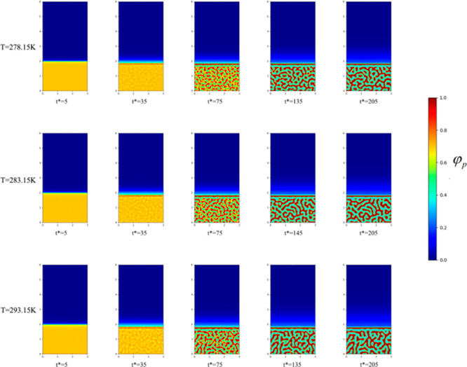
Microscopic simulation diagram of the PVDF membrane system at different time periods at the coagulation bath temperatures of 278.15, 283.15, and 293.15 K at top, middle, and bottom panels, respectively.
Figure 2.
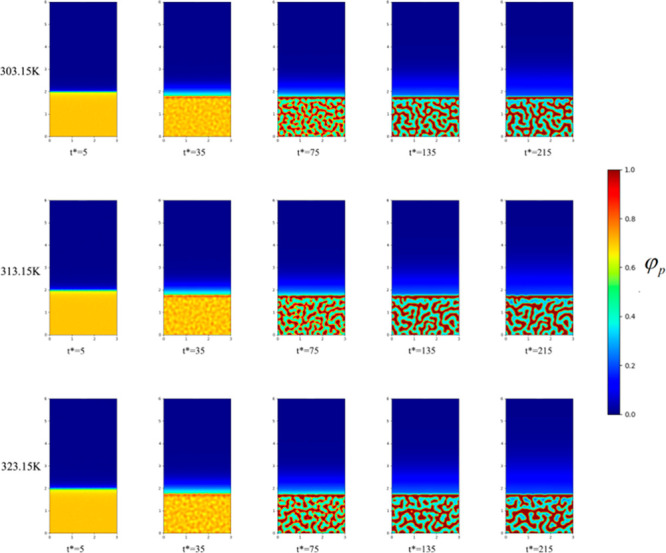
Microscopic simulation diagram of PVDF membrane system at different time periods at the coagulation bath temperature of 303.15, 313.15, and 323.15 K, at top, middle, and bottom panels, respectively.
Figure 3.
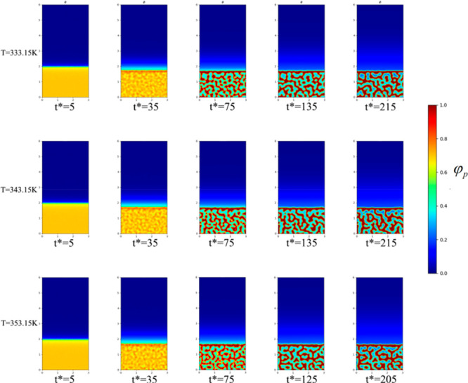
Microscopic simulation diagram of the PVDF membrane system at different time periods, when the coagulation bath temperature is 333.15, 343.15, and 253.15 K at top, middle, and bottom panels, respectively.
Figure 4.

SEM images of the PVDF membrane at different coagulation bath temperatures (T1, T2, T3, T4, T5, T6, T7, T8).
This is because the entire film formation process was controlled by thermodynamics, and the liquid–solid and liquid–liquid phase-separations control the film formation process at low and high temperatures, respectively. The temperature change of the coagulation bath induced a decrease in the number of pores in the outer skin layer but an increase in the size was identified, where the pores were changed from crack-like to round-like pores. The finger-like pores near the outer layer were extended, and the pore structure became loose. However, the mechanical strength of the membrane itself was somewhat self-conductive. The simulation results revealed that when the casting liquid was rapidly immersed in the solidification bath, the liquid–liquid phase-separation time became shorter as the temperature increased. This resulted in a thinner skin layer and asymmetric membranes with porous structures. The finding indicates the important role that thermodynamics and kinetics play in the process of membrane formation because the final morphologies of membrane pores were different. The experimental results demonstrated that the pure water flux of the prepared membrane and the change of membrane porosity also followed the same law.
4.2. Effect of Coagulation Bath Temperature on PVDF Crystallization
Given the regularity of the PVDF polymer chain, when the temperature of the solidification bath was lower than the temperature of the casting liquid, PVDF could be crystallized from the solution to form pure crystalline and liquid phases. This, in turn, could reduce the free energy of mixing. This phase separation process is generally called the “solid-liquid phase separation”. Simulations indicated that the instantaneous liquid–liquid phase separation occurred when the casting liquid was immersed in the gel bath. This yielded a thinner skin layer and porous structure, which indicated that with the increase in the temperature of the solidification bath, the system became more conductive for the occurrence of liquid–liquid phase separation.
Moreover, relatively lower coagulation bath temperatures were required if solid–liquid phase separation was anticipated to occur. Due to the temperature change, polymer crystallization first occurred in the form of a dispersed phase. With these crystals as the center, the polymer crystals gradually became larger to link with each other, which formed a network-like support structure. Moreover, the solution was transformed into a gel state and solidified. Overall, the lower is the temperature of the coagulation bath, the easier it is to form solid polymer crystallization with a network-like support structure. As the temperature decreased, the crystallization band of PVDF was easier to form, and at 333.15, the crystallization of PVDF was gradually perfected. The lower temperature was conductive for the crystallization of PVDF, because the decrease of temperature will cause the weakening of molecular motion and the weakening of thermal motion of other motion units such as chain segments, The polymer chains will be easy to arrange in order, and the crystal nucleus will be easier to form, potentially driven by the high temperature-induced phenomenon. Particularly, as temperature increased, the polymer-lean phase and the polymer-rich phase both continued exchanging polymer and solvent molecules between them until one of the regions was fully cured. If the curing process of the two phases was delayed, the film discrete pores or dead volumes were formed in the polymer, thereby causing the complete crystallization of the polymer. The crystallization lines at different temperatures are shown in Figure 5. As seen, as the coagulation bath temperature increased, the crystallization lines moved in the direction of the polymer/nonsolvent axis. This phenomenon was due to the higher coagulation bath temperature, thus making the molecules move faster and strengthening the energy of the system. This facilitated the system to diffuse and form a nascent membrane, which accelerated the crystallization of PVDF during the aggregation process, making the membrane pore structure looser, while promoting the water permeability of the membrane. Moreover, the thickness of the film was also in a highly swollen state before curing, which made the structure of the PVDF film loose and the film body, ultimately, thickened. Figure 6 shows the simulation comparison diagrams, when the temperature was 278.15, 298.15, 313.15, 333.15, and 353.15 K, and the time steps were 35, 55, 85, 135, and 225. Figure 6 shows that at the same time of membrane evolution, the influence of coagulation bath temperature on membrane structure is significant. With the increase of coagulation bath temperature, the porosity of the membrane can be improved at the same time. In the same time, with the increase of temperature, the structure of the membrane changes, which is reflected in the greatly shortened time for the formation of the cortex, which affects the formation of the sublayer to a certain extent. In the same time, with the increase of temperature, the molecular motion speed of the casting solution system accelerates. When the cortex is completely formed, the amount of solvent diffused into the nonsolvent in a shorter time increases, which makes the number of pores in the membrane increase. When the time step is above 135, the morphology of the membrane has been basically formed.
Figure 5.
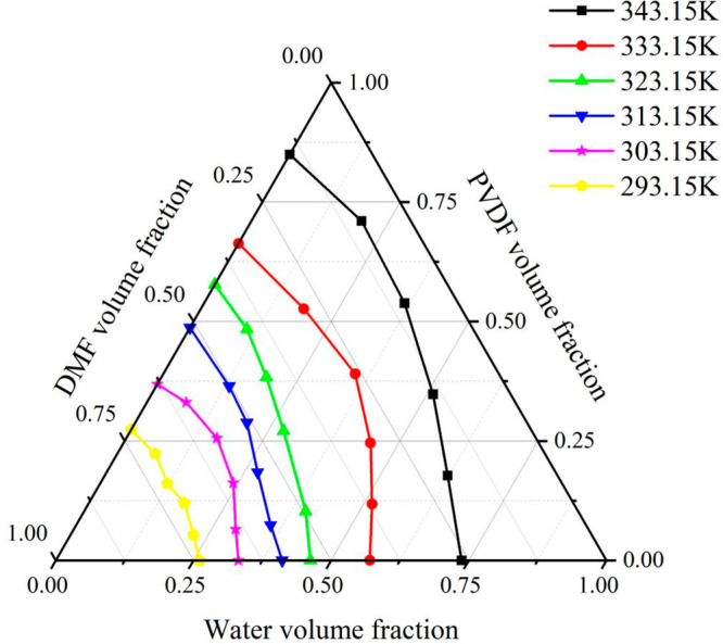
Crystallization lines of PVDF/DMF/H2O system at different temperatures.
Figure 6.

Time comparison of PVDF crystallization process at different temperatures.
4.3. Membrane Morphology
Figure 4 is the scanning electron microscope of the film prepared under different coagulation bath temperatures. The prepared membranes were all asymmetrical structures, and the membrane pore structure was mainly manifested as a cell-like structure, a granular structure, a finger hole structure. The surface structure of the membrane indicated that as the coagulation bath temperature increased, the pores of the membrane became larger, and the number increased. Figure 7 shows the relationship between the porosity and membrane pore size as a function of coagulation bath temperature.
Figure 7.

Trend of porosity and pore size with temperature.
When the temperature of the coagulation bath was low numerous phenomena were identified. In particular, the membrane body did not shrink, the obtained membrane exhibited a small pore size and dense pores, and the macro-porous structure developed longitudinally along the film thickness direction. As the temperature of the coagulation bath increased, other phenomena were discerned. Specifically, the film formation time was shortened, the pores of the obtained film appeared as large holes, the pore size of the film gradually increased, and the water flux significantly increased, the number increased, but the retention rate decreased. Figure 8 illustrates the rejection coefficient and water flux as a function of coagulation bath temperature. When the temperature of the coagulation bath reached 333.15 K, the film body considerably shrunk. As a result, cracks emerged on the film surface, possibly driven by stress concentration of the film, caused by the high temperature.
Figure 8.

Variation trend of rejection coefficient and water flux with temperature
When the temperature of the solidification bath was low, as indicated by the thermodynamic properties, the mass transfer speed between the casting liquid and the solidification bath became slow. Thus, on one hand, the formation of voids was avoided, while on the other hand, the gelation rate was slowed down due to the slow mass transfer rate, which was conductive for the formation of a networked structure. As the temperature increased, the amount of nonsolvent diffused into the sublayer increased as well. These increases caused the phenomenon, we identified, namely, the phase separation time decreased, and the diffusion rate of the solvent was lower than that of the nonsolvent, which implied that the porosity of the resulting film varied with the temperature of the coagulation bath, which is consistent with the conclusion of Frommer.42
5. Conclusions
In this study, we add the variable of temperature to the existing phase field model and conduct relevant experiments to compare with the simulation process, and the results show that
-
(1)
As the temperature of the coagulation bath increased, the membrane pore structure became loose, the water flux increased, and the rejection rate of BSA decreased.
-
(2)
With the increase of solidification bath temperature, the system is more conducive to the occurrence of liquid–liquid phase separation, and the phase separation time is reduced, resulting in more reticular structures in the sublayer. The thermodynamic changes in the system increased, and the changes in the skin were dominated by the delayed liquid–liquid phase separation, which made it easier for PVDF to form crystals and facilitated the formation of macropores and obtained a thicker and denser skin.
-
(3)
For this reason, the temperature of the coagulation bath was chosen to be between 35 and 45 °C in order to integrate the best temperature for the coagulation bath to reduce energy consumption and to obtain the best results for the membrane performance.
In the next step, we will study the more suitable coagulation bath temperature range at different initial PVDF concentrations and temperatures, because different initial concentrations will affect the growth of cortex and sublayer, and change the type and speed of phase.
Acknowledgments
The authors thank the Key R&D Projects in Shaanxi Province “Research and application of key technologies of high-quality fertilizer conversion of organic waste” (project number: 2021NY-188) for financial support. The authors would like to acknowledge School of Urban Planning and Municipal Engineering of Xi’an Polytechnic University for providing experimental equipment.
The authors declare no competing financial interest.
References
- Min L.; Liu S.; Xu Z.; Wei Y.; Yang H. Formation of microporous polymeric membranes via thermally induced phase separation: A review. Front. Chem. Sci. Eng. 2016, 10, 57–75. 10.1007/s11705-016-1561-7. [DOI] [Google Scholar]
- Wang D. M.; Lai J. Y. Recent advances in preparation and morphology control of polymeric membranes formed by nonsolvent induced phase separation. Curr. Opin. Che. Eng. 2013, 2, 229–237. 10.1016/j.coche.2013.04.003. [DOI] [Google Scholar]
- Fang P.; Yang C.; Shao R.; Zhou L.; Liu L. Ternary Phase-Field Simulations of the Skin-Sublayer Structures in Poly(vinylidene fluoride) Microporous Membranes Prepared by a Nonsolvent-Induced Phase Separation. ACS Omega 2021, 6, 7444–7453. 10.1021/acsomega.0c05982. [DOI] [PMC free article] [PubMed] [Google Scholar]
- Kim J. F.; Kim J. H.; Lee Y. M.; Drioli E. Thermally induced phase separation and electrospinning methods for emerging membrane applications: A review. Aiche. J. 2016, 62, 461–490. 10.1002/aic.15076. [DOI] [Google Scholar]
- Wu W.; Zhang X.; Qin L.; Li X.; Meng Q.; Shen C.; Zhang G. Enhanced MPBR with polyvinylpyrrolidone-graphene oxide/PVDF hollow fiber membrane for efficient ammonia nitrogen wastewater treatment and high-density Chlorella cultivation. Chem. Eng. J. 2020, 379, 122368–122380. 10.1016/j.cej.2019.122368. [DOI] [Google Scholar]
- Belgada A.; Achiou B.; Alami Younssi S.; Charik F. Z.; Ouammou M.; Cody J. A.; Benhida R.; Khaless K. Low-cost ceramic microfiltration membrane made from natural phosphate for pretreatment of raw seawater for desalination. J. Eur. Ceram. Soc. 2021, 41, 1613–1621. 10.1016/j.jeurceramsoc.2020.09.064. [DOI] [Google Scholar]
- Elsaid K.; Kamil M.; Sayed E. T.; Abdelkareem M. A.; Wilberforce T.; Olabi A. Environmental impact of desalination technologies: A review. Sci. Total Environ. 2020, 748, 141528. 10.1016/j.scitotenv.2020.141528. [DOI] [PubMed] [Google Scholar]
- Zhong Q.-Z.; Pan S.; Rahim M. A.; Yun G.; Li J.; Ju Y.; Lin Z.; Han Y.; Ma Y.; Richardson J. J.; Caruso F. Spray Assembly of Metal–Phenolic Networks: Formation, Growth, and Applications. ACS Appl. Mater. Interfaces 2018, 10, 33721–33729. 10.1021/acsami.8b13589. [DOI] [PubMed] [Google Scholar]
- Mulder M.Basic principle of membrane technology; Kluwer. Academic, 1992; pp 1–109. [Google Scholar]
- van de Witte P.; Dijkstra P.J.; van den Berg J.W.A.; Feijen J. Phase separation processes in polymer solutions in relation to membrane formation. J. Membr. Sci. 1996, 117, 1–31. 10.1016/0376-7388(96)00088-9. [DOI] [Google Scholar]
- Fujii Y.; Iwatani H.; Kigoshi S. Morphological structure of the membranes prepared from polymer solutions. Polym. J. 1992, 24, 737–748. 10.1295/polymj.24.737. [DOI] [Google Scholar]
- Cohen C.; Tanny G. B.; Prager S. Diffusion-controlled formation of porous structures in ternary polymer systems. J. Polym. Sci. Polym. Chem. 1979, 17, 477–489. 10.1002/pol.1979.180170312. [DOI] [Google Scholar]
- Yilmaz L.; Mchugh A. J. Analysis of nonsolvent-solvent-polymer phase diagrams and their relevance to membrane formation modeling. J. Appl. Polym. Sci. 1986, 31, 2847–2847. 10.1002/app.1986.070310837. [DOI] [Google Scholar]
- Yilmaz L.; Mchugh A. J. Modelling of asymmetric membrane formation. I. Critique of evaporation models and development of a diffusion equation formalism for the quench period. J. Membr. Sci. 1986, 28, 287–310. 10.1016/S0376-7388(00)82040-2. [DOI] [Google Scholar]
- Cheng L.-P.; Soh Y. S.; Dwan A.-H.; Gryte C. C. An improved model for mass transfer during the formation of poly- meric membranes by the immersion precipitation process. J. Polym. Sci. B Polym. Phys. 1994, 32, 1413–1425. 10.1002/polb.1994.090320813. [DOI] [Google Scholar]
- Khansary M. A.; Marjani A.; Shirazian S. On the search of rigorous thermo-kinetic model for wet phase inversion technique. J. Membr. Sci. 2017, 8, 18–33. 10.1016/j.memsci.2017.05.050. [DOI] [Google Scholar]
- Maggay I. V.; Yu M.; Wang D.; Chiang C.; Chang Y.; Venault A. Strategy to prepare skin-free and macrovoid-free polysulfone membranes via the NIPS process. J. Membr. Sci. 2022, 655, 120597–120660. 10.1016/j.memsci.2022.120597. [DOI] [Google Scholar]
- Zhang L.; Shi Y.; Wang T.; Li S.; Zheng X.; Zhao Z.; Feng Y.; Zhao Z. Fabrication of novel anti-fouling poly(m-phenylene isophthalamide) ultrafiltration membrane modified with Pluronic F127 via coupling phase inversion and surface segregation. Sep. Purif. Technol. 2022, 282, 120106–120120. 10.1016/j.seppur.2021.120106. [DOI] [Google Scholar]
- Hoogerbrugge P. J.; Koelman J. Simulating Microscopic Hydrodynamic Phenomena with Dissipative Particle Dynamics. Epl 1992, 19, 155–160. 10.1209/0295-5075/19/3/001. [DOI] [Google Scholar]
- Chen; Long-Qing Computer simulation of spinodal decomposition in ternary systems. Acta. Materialia. 1994, 42, 3503–3513. 10.1016/0956-7151(94)90482-0. [DOI] [Google Scholar]
- Phillies; George D. J. Universal scaling equation for self-diffusion by macromolecules in solution. Macromolecules 1986, 19, 2367–2376. 10.1021/ma00163a006. [DOI] [Google Scholar]
- Phillies G. The hydrodynamic scaling model for polymer dynamics. J. Non-cryst. Solids. 1988, 5, 214–219. 10.1016/0920-5632(88)90043-6. [DOI] [Google Scholar]
- Ashtiani S.; Khoshnamvand M.; Cihal P.; Dendisova M.; Randova A.; Bousa D.; Shaliutina Kolesova A.; Sofer Z.; Friess K. Fabrication of a PVDF membrane with tailored morphology and properties via exploring and computing its ternary phase diagram for wastewater treatment and gas separation applications. Rsc. Adv. 2020, 10, 40373–40383. 10.1039/D0RA07592B. [DOI] [PMC free article] [PubMed] [Google Scholar]
- Munshi T.; Redha B.; Feeder N.; Meenan P.; Blagden N. Impact of Mixed Solvent on Co-Crystal Solubility, Ternary Phase Diagram, and Crystallization Scale Up. Cryst. Growth. Des. 2016, 16, 1817–1823. 10.1021/acs.cgd.5b00908. [DOI] [Google Scholar]
- Yin C.; Dong J.; Li Z.; Zhang Z.; Zhang Q. Ternary phase diagram and fiber morphology for nonsolvent/DMAc/polyamic acid systems. Polym. Bull. 2015, 72, 1039–1054. 10.1007/s00289-015-1324-5. [DOI] [Google Scholar]
- Felmer P. L.; del Pino M. On the basic concentration estimate for the Ginzburg-Landau equation. Differ. Integral. Equ. 1998, 11, 771–779. 10.57262/die/1367329670. [DOI] [Google Scholar]
- Cahn J. W.; Hilliard J. E. Free Energy of a Nonuniform System. I. Interfacial Free Energy. J. Chem. Phys. 1958, 28, 258–267. 10.1063/1.1744102. [DOI] [Google Scholar]
- Cahn J. W. On spinodal decomposition in cubic crystals. Acta. Metall. Sin. 1962, 10, 179–183. 10.1016/0001-6160(62)90114-1. [DOI] [Google Scholar]
- Allen S. M.; Cahn J. W. A microscopic theory for antiphase boundary motion and its application to antiphase domain coarsenin. Acta. Metall. Sin. 1979, 27, 1085–1095. 10.1016/0001-6160(79)90196-2. [DOI] [Google Scholar]
- Huggins; Maurice L. Principles of Polymer Chemistry. J. Am. Chem. Soc. 1954, 76, 2854–2854. 10.1021/ja01639a090. [DOI] [Google Scholar]
- Denny Kamaruddin H Some observations about the application of Fick’s first law for membrane separation of multicomponent mixtures. J. Membr. Sci. 1997, 135, 47–159. 10.1016/S0376-7388(97)00142-7. [DOI] [Google Scholar]
- Yang T.-H.; Lue S. J. Coupled concentration-dependent diffusivities of ethanol/water mixtures through a polymeric membrane: Effect on pervaporative flux and diffusivity profiles. J. Membr. Sci. 2013, 443, 1–9. 10.1016/j.memsci.2013.05.002. [DOI] [Google Scholar]
- Kowert B. A.; Watson M. B.; Dang N. C. Diffusion of squalene in n-alkanes and squalane. J. Phys. Chem. B 2014, 118, 2157–2163. 10.1021/jp411471r. [DOI] [PubMed] [Google Scholar]
- Bottino A.; Camera-Roda G.; Capannelli G.; Munari S. The formation of microporous polyvinylidene difluoride membranes by phase separation. J. Membr. Sci. 1991, 57, 1–20. 10.1016/S0376-7388(00)81159-X. [DOI] [Google Scholar]
- Wilke C. R.; Chang P. Correlation of diffusion coefficients in dilute solutions. Aiche. J. 1955, 1, 264–270. 10.1002/aic.690010222. [DOI] [Google Scholar]
- Saxena R.; Caneba G. T. Studies of spinodal decomposition in a ternary polymer-solvent-nonsolvent system. Polym. Eng. Sci. 2002, 42, 1019–1031. 10.1002/pen.11009. [DOI] [Google Scholar]
- Zhou B.; Powell A. C. Phase field simulations of early stage structure formation during immersion precipitation of polymeric membranes in 2D and 3D. J. Membr. Sci. 2006, 268, 150–164. 10.1016/j.memsci.2005.05.030. [DOI] [Google Scholar]
- Wang X.; Zhang L.; Sun D.; An Q.; Chen H. Effect of coagulation bath temperature on formation mechanism of poly(vinylidene fluoride) membrane. J. Appl. Polym. Sci. 2008, 110, 1656–1663. 10.1002/app.28169. [DOI] [Google Scholar]
- Hu X.; Xiao C.; Liu M. Effects of coagulation bath temperature on polyurethane-based hollow fiber membrane morphology. Fiber. Polym. 2014, 15, 1429–1435. 10.1007/s12221-014-1429-8. [DOI] [Google Scholar]
- Thurmer M. B.; Poletto P.; Marcolin M.; Duarte J.; Zeni M. Effect of non-solvents used in the coagulation bath on morphology of PVDF membranes. Mater. Res. Express. 2012, 15, 884–890. 10.1590/S1516-14392012005000115. [DOI] [Google Scholar]
- Wu L. Effect of Coagulation Bath on Poly(vinylidene fluoride) Membrane Structure. J. Text. R. 2004, 25, 12–14. [Google Scholar]
- Frommer M.A.; Feiner I.; Kedem O.; Bloch R. The mechanism for formation of “skinned” membranes: II. Equilibrium properties and osmotic flows determining membrane structure. Desalination 1970, 7, 393–402. 10.1016/S0011-9164(00)80207-6. [DOI] [Google Scholar]