Abstract
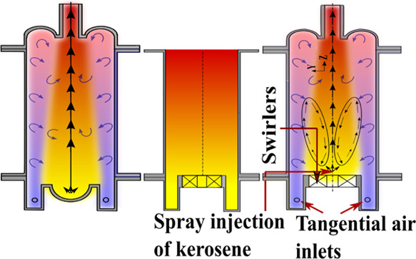
In the present study, a novel hybrid swirl combustor is designed to reduce the size and complexity of a conventional gas turbine combustor. In this combustor, a dual-swirl pattern is adopted by providing the central vane swirler (45° vane angle) and circumferential tangential injection scheme to achieve higher recirculation of heat and combustion products inside the combustor. Numerical and experimental studies are carried out to understand the flow patterns and combustion characteristics in this high mass–heat interacting environment. Initially, computational studies were carried out to find the optimum geometry for greater recirculation and interaction among the reacting species inside the combustor. Liquid fuel (kerosene) is sprayed into the combustor for two thermal inputs of 25 and 50 kW. Three cases were studied to analyze the effect of bowl recirculation and tangential air inputs in addition to the swirlers. The hybrid swirl, formed by the counter-flow pattern, helps in achieving low and uniform temperature throughout and assists in flame anchoring. The tangential air flow provides a push to the combustion products from the downstream to the central recirculation zone of the combustor. The combined effect of central and tangential swirlers helps in attaining a more distributed combustion. The CO and NO emissions reduced with the use of hybrid swirl.
1. Introduction
Conventional gas turbine can-combustors are of diverging annular shape to achieve a greater swirl, thus achieving a greater power generation. Huge recirculation promised by swirl flow helps in achieving the better mixing of the fuel and oxidizer and also enhances the residence time; this ensures a complete homogeneous reaction zone. MILD/flameless combustion is a novel method developed significantly in the last two decades to achieve distributive reaction along with ultralow emissions, characterized by elevated reactant temperature, lower and uniform combustor temperature, and low NOx emissions.1−9 Similarly, HiTAC and colorless distributed combustion methodologies were developed to attain a more distributed combustion to combat emissions.10−14 These can-combustors have been adopted and modified in numerous studies to achieve ultralow emissions and distributive combustion phenomena such as MILD/flameless combustion.15−19 The can-combustors used in the gas turbine applications have many advantages including the recirculation from the divergent section which is useful to maintain a lower peak temperature. In addition, there are provisions for secondary air inlets and diluent inputs at the downstream locations to achieve complete combustion with reduced CO and NOx emissions. Such a practical gas turbine combustor with annular chambers and secondary inlets in multiple zones in the downstream direction is, however, complex in design, maintenance, and operation. The diverging part for swirl generation increases the cross-sectional area of the combustor. Consequently, the gas turbine size also increases. Achieving flameless combustion with liquid fuel is also difficult using such combustors. In the present study, a novel combustor is designed to adapt with both primary and secondary oxidizers in a cylindrical-shaped combustor without an annular zone around the combustor. It is an attempt to preserve the high recirculation characteristics to achieve distributive reaction with ultralow emissions in this novel hybrid swirl combustor.
Many studies have considered single- and dual-swirl configurations to check the reduction in peak temperature and emissions with enhanced efficiency.20−28 Sung and Choi20 considered co-swirl and counter-swirl flows to study the flame behavior for a 10 kW coal–methane–air premixed combustion burner with varied inner swirler and fixed outer swirler orientations. It was observed that the counter-swirl configuration was able to generate a wider and distributive reaction zone owing to the large shear force produced compared to the co-flow swirl condition. Weigand et al.21 developed a dual co-swirl combustor to study methane/air diffusion flames with three different thermal inputs 7.6, 10.3, and 34.9 kW and observed a similar flow pattern with higher inner recirculation and lower outer recirculation velocities for each flame. Chen et al.22,23 carried out large eddy simulation (LES) analysis on the burner21 to study the flame structures and flame stabilization, mixing of air and fuel, and the interactions between the self-excited oscillations for methane/air partially premixed flames. The predictions of the flow distributions and flame characteristics from the LES studies were very close to the experimentally observed ones. Different mixing behaviors were observed for the stable and unstable flames. Different mass inputs through the two swirlers cause oscillating radial motion of the fuel jets, resulting in an enhanced fuel–air mixing inside the domain. Yang et al.24 considered separated dual-swirl flames with counter-rotating radial swirlers of 30° vanes with swirl numbers of 0.6 and 0.8 to study the phases of ignitions and modes of ignition failure. They identified five ignition phases for successful ignition: the kernel generation, flame propagation, flame residence, flame growth, and stable combustion. The flow of air around the ignitor is a crucial parameter and should be maintained at a low velocity in order to allow the flame kernel to be captured in the flow recirculation. In the recent studies,29,30 researchers have adopted two-stage swirl flow motion to achieve high recirculation and obtained different flame shapes and characteristics.
Liquid fuels are primarily used for gas turbine and industrial applications. In case of liquid fuels, achieving low peak temperature and uniform temperature throughout the combustor domain is quite complicated and challenging. Maintaining a strong recirculation within the combustor is necessary for preheated and diluted reactants to stabilize the flame with these characteristics. Initial studies15,31 stressed the importance of the improved recirculation for evaporating and mixing of fuel droplets with air to achieve flameless combustion. Mahendra Reddy et al.16,17 achieved MILD combustion characteristics using kerosene fuel with tangential air inlets to the combustor and by modifying the combustor geometries to allow more recirculation into the combustors. Table 1 shows the list of literature studies that considered swirl combustion and flameless combustion to achieve low emissions for various thermal input conditions. The dual-swirl methods could help in achieving better combustion and emission characteristics. However, they are yet to be adopted widely for liquid fuel combustion. Hadef and Lenze32 studied the effect of both co- and counter-swirl on the droplet dynamics for spray flames using dual-phased doppler anemometry. They observed that the counter-rotating swirlers generated larger turbulence and hence resulted in better fuel–air mixing than the co-swirlers. Droplet density was higher at the vicinity of the burner axis, and finer atomization was observed. Huang et al.33 considered co-swirlers for their LES study of kerosene/air combustion for high-pressure conditions up to 5 MPa. The interactions of high-pressure combustion with the high swirl flow patterns are shown in their numerical studies. The high swirl motion of air caused flow reversal near the center of the combustor for lean conditions, whereas the recirculation reduced for rich mixtures. As the pressure increased from 3 to 5 MPa, reduction in the oscillation frequency of the precessing vortex core was observed. In another study, Sharma et al.34 considered various geometries consisting of swirl flow of air, dilution with air staging for a high dilution ratio and to obtain an optimal combustor design to be used for gas turbine applications. It was observed that a co-swirl condition was able to produce greater recirculation than the counter-swirl flow case. The combustor geometry resembled the conventional can-combustor with multiple inlets of air at different downstream locations and annular jacket. In a different study Sharma et al.35 injected fuel at an asymmetric location to enhance the dilution ratio (Rdil) for low to moderate thermal intensities for kerosene and biodiesel combustion and were able to increase the flame stability in the MILD combustion regime.
Table 1. List of Literature Studies for Swirl and Low Emission Combustors with Thermal Intensities Considered.
| fuels | Qth (kW) |
 (MW/m3) (MW/m3) |
emissions | ref |
|---|---|---|---|---|
| kerosene | 21.5–84.7 | 5.4–21 | CO: 10–40 ppm | (17) |
| NOx: 5–20 ppm | ||||
| propane | 10–15 | 0.18–0.27 (approx.) | CO: 0.1–3000 (dry ppmv@3% O2) | (36) |
| NOx: 10–100 (dry ppmv@3% O2) | ||||
| HFO, coal, natural gas | 580 | 0.024 | NOx: 100–200 ppm (dry) | (31) |
| kerosene and biodiesel | 25–53 | 6.34–13.3 | CO: 5–80 ppm(@15% O2) | (35) |
| NOx: 2–34 ppm(@15% O2) | ||||
| natural gas | 3.5–25 | 5–453 | CO: 10–280 ppmvd(@15% O2) | (37) |
| NO: 0–25 ppmvd(@15% O2) | ||||
| methane | 15 | 18.2 | (38) | |
| natural gas | 10–20 | 0.2–0.4 (approx.) | CO: 0–20 ppm | (39) |
| NOx: 0–50 ppm |
It is observed from the existing literature that the dual-swirl combustor is able to produce a wider homogeneous reaction zone as it extends the flame radially. However, there are no provisions from dual-swirl configurations to ensure the recirculation in the longitudinal direction in addition to the transverse swirl. Therefore, a hybrid recirculation method through swirlers and tangential inlets along with the bowl curvature effect at the outlet side is considered in this present study. The present study compares the effect of the hybrid swirl on the combustion characteristics and emissions with the base case of the cylindrical combustor. Tangential air inlets are provided in addition to the vane swirler to expand the flame in longitudinal and transverse directions to achieve better recirculation. The swirl effect is intense in the tangential pattern since it results in a large centrifugal force. The strong tangential air injection scheme replaces the use of an annular jacket for secondary air inlets in a conventional gas turbine combustor. This high recirculation becomes crucial in achieving the preheated and diluted environment in order to reduce the combustor’s complexity and size.
Kerosene is used as the fuel, and it is represented by C12H23 species for the CFD computations. Different combustor geometries combined with different spray nozzle configurations and swirl flow conditions are initially studied numerically to understand the recirculation pattern inside the combustors. These parameters are varied with low peak temperature and emissions inside the combustor as the primary objective. The optimal combustor geometry is fabricated based upon the computational analysis, and experiments are carried out for the thermal input conditions of 25 and 50 kW. Non-premixed combustion under atmospheric pressure conditions with a global mixture equivalence ratio range of 0.7–1.3 is considered in this study. The peak and radial variation of temperature and the CO and NOx emissions at the outlet are presented in this paper.
2. Computational Domain and Numerical Methodology
2.1. Design of the Combustor
The motivation behind the present study is to design a simple combustor without incorporating the diverging part yet maintaining highly intense recirculation at the same level. The parameters that were varied include the diameter of the cylinders and recirculation bowl, length of the cylinders, diameter of the tangential air inlet ports, vane angles of the swirlers, and spray cone angle of the nozzles to stabilize the flame and improve recirculation within the computational domain for these thermal input conditions. Initially, the authors contemplated the idea of employing the multi-bowl-shaped domain at both upstream and downstream locations of the combustor, as shown in Figure 1a, to enhance the recirculation by the curvature effect. The air was supplied through the tangential inlets. The cold flow analysis showed a flow reversal effect because of the bowls at the downstream location. However, for the moderate thermal input conditions, the recirculation was not sufficient to stabilize the distributed flame inside the combustor. The length of the combustors was varied simultaneously to amplify the bowl effect and to allow larger residence time for the reaction zone to be shifted upstream. The recirculation died out eventually due to the lack of the central low pressure zone which was generally observed in the case of straight can-combustors. Subsequently, the upstream bowl was replaced with annular straight vane swirlers with eight vanes and 45° vane angle, leading to a swirl number of 0.71 after contemplating various computations with these operating parameters.
Figure 1.
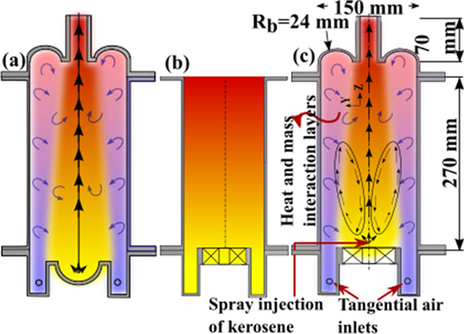
Different combustor designs considered: (a) with a bowl-shaped combustor at both the inlet and outlet, (b) with swirlers replacing the inlet bowl and without the bowl at the outlet, case C(2), and (c) with both the tangential inlets and swirler with the recirculation bowl, case C(3).
The thermal input application for the geometry was set for a medium range of 25–100 kW (in steps of 25 kW). However, it was observed that the flames were not able to stabilize with this configuration irrespective of varying the other geometrical parameters such as the diameter and length of the cylinders. The reason behind this observation was attributed to a low recirculation generated from the recirculation bowl. This is because of a high localization of heat generated due to the high thermal input case. Thus, to achieve better recirculation using the hybrid swirl method for higher thermal input conditions, the geometry modifications need to be modified, and further scaling analysis needs to be conducted that will fall in the future scope. This limits the maximum working thermal input conditions to 50 kW in the present study. The primary objective of this manuscript is, therefore, to test the hypothesis which is as follows: a hybrid air injection scheme works better in reducing the emissions and achieving a uniform combustion zone.
The oxidizer was distributed to the swirler and tangential ports as per the operating conditions. The vanes were orientated in the opposite direction (counter-clockwise from the outlet side) to the tangential air inlets to produce pathlines similar to counter-swirl burners. The air supply from the central vane swirlers increases the radial recirculation, whereas the peripheral tangential air inlets with high momentum aided by the bowl-shaped geometry increase the longitudinal recirculation. This helped in better mixing of the air with the fuel droplets and homogenizing the zone by forming the extended recirculation zone throughout the combustor. Three cases of different geometry orientations are considered to study the effect of bowl recirculation and tangential air inputs: C1: straight cylindrical open combustor without bowl recirculation and central-swirl air inlets only (Figure 1b, no air flow is allowed to enter through the tangential inlets), C2: with bowl recirculation but without the tangential air inlets (similar to the case of C1 but with an end-bowl structure), and C3: with the bowl recirculation and tangential air inlets. A comparison of C1 and C2 will show the effectiveness of bowl structures at the outlet, whereas the comparison of C2 and C3 will show the effectiveness of the tangential inputs. The total air flow was given to the swirler for C1 and C2, whereas the total air inlets were divided to the swirler and tangential part for a constant equivalence ratio such that the tangential air varies from 0 to 40% by mass, in steps of 10%, for C3. For example, C3_70/30 denotes that 70% of total airflow is given through swirlers and 30% through the tangential ports.
2.2. Numerical Modeling
The geometry of the hybrid swirl combustor is designed as two-part swirl inputs for air flow. Peripheral swirl flow is provided through four tangential air inlets of 6.8 mm port diameter at an upstream location of 5 cm from the fuel nozzle. This allowed a counter-clockwise annular swirl flow of air near the walls of the combustor. Axial swirl flow is further provided using the swirlers with a hub length and diameter of 20 and 22 mm, respectively. Eight vanes with a vane angle of 45° are considered with an outer diameter of 80 mm. A torus-shaped hemispherical bowl is provided at the end of the downstream side of the combustor, as shown in Figure 1a,c. The bowl helps in improving the recirculation by reverting the tangential swirl flow toward the fuel nozzle of the combustor. The schematic diagram for the combustor is shown in Figure 2. Fuel is injected along the central axis of the combustor. The pressure swirl fuel nozzle with a 45° solid cone angle is considered for different thermal inputs of 25 and 50 kW. Rosin-Rammler distribution is assumed for the spread of fuel droplets with droplet diameters varying from 5 to 45 μm and a Sauter mean diameter of 20 μm. The combustor performance is tested for a wide range of equivalence ratios of 0.7–1.3 for both thermal input conditions. All simulations are run with the adiabatic wall boundary condition and atmospheric pressure condition. The inlet temperature of both fuel and air is maintained at 300 K for all the cases. The continuity, momentum, energy, and species conservation equations are solved using the corresponding iterative methods available in the commercial Ansys-Fluent CFD solver for resolving the high swirl conditions. The Reynolds stress model is considered for the closure of the turbulence viscosity since it is suitable for resolving high swirl flows. Radiation modeling is carried out using the discrete ordinate (DO) model which is the best suitable model for the present formulation.40 Turbulence–chemistry interaction is modeled using the β-PDF approach which is observed to closely predict the experimental results. Energy, momentum, mean mixture fraction, and variance terms are discretized with second-order upwind schemes. Turbulent kinetic and dissipation rates are correspondingly discretized with first-order upwind schemes. The Favre-averaged (denoted by tilda) governing equations used for this model are as follows:
Figure 2.
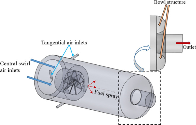
Computational domain with hybrid air injection with central fuel supply and the hemispherical bowl at the outlet adopted for the numerical simulations.
Continuity
| 1 |
Momentum
| 2 |
where ui is the velocity in the ith direction, ρ is the density of the mixture, p is the pressure, and h is the specific enthalpy of the mixture. According to the Boussinesq hypothesis, the Reynolds stress term is modeled using turbulent viscosity μt.
The steady-state Reynolds stress model equations solve the following equations
 |
3 |
The thermochemistry is modeled using the mixture fraction approach. The equilibrium model can be used to model the chemistry once it has been mixed, while the steady diffusion flamelet model can be used to model the chemistry near chemical equilibrium once it has been mixed. The mixture fraction, f, represents the mass fraction in the fuel stream that originated from the mixture. Therefore, it represents the local mass fraction in all fuel streams of the elements burned and unburned (C, H, and so on). Chemical reactions conserve atomic elements, making this approach elegant. Therefore, the governing equation does not contain a source term for the mixture fraction, which is a conserved scalar quantity. As a result, combustion is simplified to a mixing problem, with no difficulties involved in closing nonlinear mean reaction rates. Mathematically, f is defined as
| 4 |
where Zi is the elemental mass fraction of element i. Under high turbulent flow conditions, the diffusivities of each
species can be assumed to be equal since momentum is dominating in
this regime. Therefore, the species equations can be reduced to one
single conservation equation of mixture fraction since elements are
conserved throughout. The corresponding Favre-averaged mixture fraction
(f̅) and mixture fraction variance ( ) transport equations are solved. The prediction
of the turbulent reacting flow is concerned with the prediction of
the averaged values of the fluctuating scalars such as species fraction,
temperature, and density. The assumed-shape probability density function
(PDF) approach is considered as its closure model when the non-premixed
model is used. In the present model, the β-function PDF shape
is used.
The soot estimation and the radiation effect from the soot are critical in liquid fuel combustion especially under moderate to high thermal input conditions. Therefore, the radiative heat transfer from the gas medium, soot, and walls is taken into consideration. The DO method is implemented to model the radiative heat transfer from the gas medium. The theta and phi divisions are kept at eight quantities for both parameters. The energy equations solved for the non-premixed combustion model are as below
| 5 |
The assumptions while solving the abovementioned equation are Lewis number = 1 and the pressure work and kinetic energy terms are neglected. The conduction and species diffusion terms are incorporated in the first term of the right-hand side of the equation. The total enthalpy H is defined as
| 6 |
where Yj is the mass fraction of species j and Hj is the enthalpy of the species j.
The radiative transfer equation considered in the numerical model for an absorbing, scattering, and emitting medium at position r→ in the direction s→ is
| 7 |
where a, n,φ, Ω′, σs, σ, and I are the absorption coefficient, refractive index, phase function, solid angle, scattering coefficient, Stefan–Boltzmann constant (5.7 × 10⁻⁸ W/m2 K4), and radiation intensity, respectively.
The effect of soot formation on the radiation heat transfer is modeled by considering an effective absorption coefficient for soot such that the combining effect is given as
| 8 |
where ag is the absorption coefficient of radiating gas which is computed using the weighted-sum-gray-gas model. The absorption coefficient form the soot particles is modeled as
| 9 |
where the constants have default values of b1 = 1232.4 m2/kg and bT ≈ 4.8 × 10⁻⁴ K–1. ρg is the gas mixture density, and Ysoot is the soot mass fraction. The swirl number of the 45° central vanes is obtained to be 0.71 based on the geometry band orientation of the swirlers, as given in eq 6:41
 |
10 |
where θ is the vane angle and Dh and Ds are the hub diameter and swirler diameter, respectively. The recirculation strength for the different cases is evaluated by estimating the reaction dilution ratio (Rdil) which signifies the interaction between the mass of reactants and products at any cross-sectional plane (x–y) along the length of the chamber (z-axis).16,40
| 11 |
where  is the sum of the mass flow rate of the
fuel supplied and oxidizer at the inlet and
  is the total mass flow rate of all the
species crossing a plane in both the positive and negative axial directions.
It is obtained by integrating the mass flux over the z-face area of each cell on the plane and is defined as
| 12 |
3. Experimental Setup
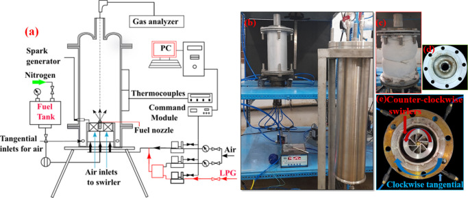
A schematic representation of the experimental setup is shown in Figure 3a. The combustor is kept vertically on a test stand. Kerosene in the fuel tank is pressurized to 9.5 bar with the help of nitrogen gas. Danfoss fuel nozzles with a solid cone angle of 45° are used to inject the fuel at the central axis of the combustor. The Sauter mean diameter (SMD) of the droplets are considered to be in the range of 17–23 μm for 9 bar pressure from the previous study.5 The properties of the industry-grade kerosene used in the experiments are stated in Table 2. Two mass flow controllers are used to supply the respective air inputs from the high-pressure storage tank to the tangential and swirl flow inlets. S-type thermocouples are used to measure the radial variation of temperature of the combustors. The central combustor cylinder is wrapped with glass wool to reduce heat loss to the environment, as shown in Figure 3c. A TESTO 350 portable flue gas analyzer is used to measure the CO, NO, and CO2 emissions from the combustors with an uncertainty of 3% in the measurements. The sampling probe is kept exposed to the emissions for sufficient time so that emission readings become steady. Each experimental condition is repeated three times, and the average results are presented to check the repeatability and control the uncertainty associated with the measurements. A Danfoss spark ignitor is used to initiate the ignition of the fuel–air mixture. The combustor was run with LPG initially to preheat the combustor so that flame stabilization is achieved. This heats the combustion zone and the walls which are needed for the recirculation and to avoid the blow-off.
Figure 3.
Schematic diagram (a) for the experimental setup with the actual setup (b), combustor (c), bowl structure at the outlet side (d), and tangential air inlets with swirlers (e).
Table 2. Properties of Industrial Grade Kerosene.
| properties | fuel (kerosene) |
|---|---|
| density (kg/m3) | 822 |
| surface tension (mN/m) | 24 |
| boiling point (K) | 445 |
| kinematic viscosity (m2/s) | 2.71 × 10⁻⁶ |
| evaporation time (ms at T∞ = 1000 K) | 8.3 |
| flash point (K) | 341 |
| SMD (μm at Pinj = 9 bar) | 20 |
4. Results and Discussion
4.1. Numerical Results
4.1.1. Flow Pattern and Recirculation
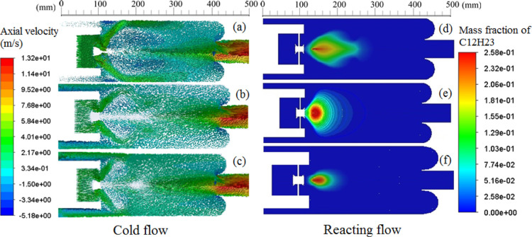
In this section, the CFD results for different operating conditions are presented. The flow patterns inside the combustor due to the interactions of the hybrid swirl flow of air and fuel spray for different equivalence ratios are analyzed. The recirculation in the combustor is controlled by the parameters such as the fraction of the air entering through the tangential air inlets, the central swirler and the bowl provided at the exit of the combustor. The optimal combustor geometry is identified by varying these parameters to achieve better mixing and recirculation in the combustor. Initially, cold flow simulations are conducted to understand the flow phenomenon in the combustor. Figure 4a–c shows the vector plots for various operating cases: 25 kW_C2, 25 kW_C3_80/20, and 50 kW_C3_80/20 by switching off the energy and species equation. It is observed that for the case of 25 kW_C3_80/20, the recirculation zone is further distributed in the radial direction. However, the length of the recirculation zone in the longitudinal direction is reduced as compared with no hybrid air injection case 25 kW_C2. This effect is caused by the counter-flow arrangement of the hybrid swirl adopted in the present study. The swirl effect due to the tangential air helped in pushing the downstream products toward the center of the vortex which gives better mixing and stabilizes the V-shaped flame. For a higher thermal input (50 kW), the corresponding air quantity is increased. Hence, the axial recirculation toward the central recirculation zone is increased further, resulting in the widespread recirculation zone. The high momentum of air compresses the reaction zone. This limits the negative velocity region very close to the fuel nozzle location, and thus, the fuel burns in the upstream region.
Figure 4.
Axial velocity vectors for non-reacting and fuel mass fraction contours for reacting flow conditions for (a,d) 25 kW_C2, (b,e) 25 kW_C3_80/20, and (c,f) 50 kW_C3_80/20 for the stoichiometric mixture.
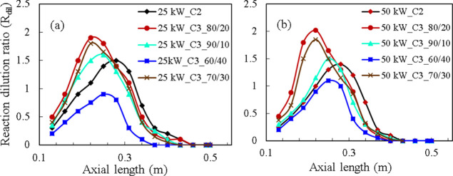
The amount of recirculation can be quantified by measuring the reaction dilution ratio (Rdil). The peak of Rdil denotes the strength of the recirculation zone, whereas the width of the Rdil dome signifies the area of the recirculation zone. Figure 5 shows the Rdil for the C2 and C3 cases and thermal inputs of 25 and 50 kW. The maximum Rdil is observed for the C3_80/20 cases of 25 and 50 kW. 50 kW cases have a marginally higher Rdil than the 25 kW thermal input conditions. It can be seen that the case C2 has a smaller peak but a wider recirculating region than the hybrid swirl cases of C3. This shows that the central recirculation zone extends to a greater downstream region for the C2 case. The strength of the recirculation increases with the tangential air inlet fraction up to 20%. The C3_70/30 case for both thermal inputs has a similar Rdil pattern to case C2_80/20 with, however, a small decrease in the magnitude. With a greater increase in the fraction of air in the tangential inlets, the recirculation dies out early and the axial flow dominates, which can be observed from the early decline of Rdil for the case of C3_60/40.
Figure 5.
Reaction dilution ratio for various cases with thermal inputs of (a) 25and (b) 50 kW.
4.1.2. Fuel Mass Fraction and Temperature Variation
4.1.2.1. Fuel Mass Fraction
Figure 4d–f shows the fuel mass fraction for the three cases, respectively. The widening of the fuel mass fraction zone with tangential injection (Figure 4e) is due to the pulling effect of the peripheral air momentum. Along with the tangential swirl pattern, the bowl effect enhances the recirculation of the products toward the center of the vortex. In the case of the combustion with the central swirler alone, the influence of the bowl was almost insignificant. The swirl pattern generated by the central swirler helps in evaporating the droplets due to the shear force. However, it is observed from the simulations that the evaporation rate is increased when the counter-flow pattern is adopted. The axial recirculation due to the combined effect of the tangential injection and bowl effect increased the interaction between the droplets and hot fluids. Also, the reverse flow helps in retarding the droplet velocity. Thus, it is observed that the evaporation is improved in the upstream side of the combustor.
4.1.2.2. Temperature Variation
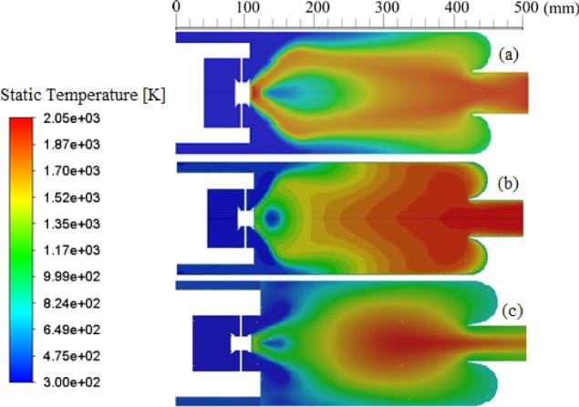
The temperature contours for the reacting flow cases of 25 kW_C2, 25 kW_C3_80/20, and 50 kW_C3_80/20 are shown in Figure 6a–c, respectively. When the orientation changes from C2 to C3, a significant widening of the combustion zone is observed (Figure 6a,b). The reaction zone begins early and can be observed in a more radially outward region. The fuel mass fraction and velocity vectors can be correspondingly seen in Figure 4, which confirms the shape of the flame and the recirculation region. Under higher thermal input conditions, the flame stabilizes at a downstream location due to high momentum of the reactants despite the early evaporation of the fuel droplets. Thus, a higher temperature increase is observed at the center of the combustor (Figure 6c).
Figure 6.
Temperature contours for (a) 25 kW_C2, (b) 25 kW_C3_80/20, and (c) 50 kW_C3_80/20 for stoichiometric mixtures.
With an increase in equivalence ratio from the lean condition of 0.7 to the rich condition of 1.3, the maximum temperature is observed at φ = 1.05 for all three cases: C1, C2, and C3, as shown in Figure 7. The temperature reduces for both lean and rich mixture conditions. With an increase in air flow rate from the stoichiometric quantity, the total heat generated gets distributed among larger quantities of mass. This reduces the peak temperature inside the combustor. For a richer mixture, the complete combustion does not take place. Thus, the net heat release rate capacity of the system reduces, which lowers the peak temperature. The recirculating flow strength increases with increased fraction of tangential air flow up to a certain limit, as shown in Figure 5. The increase in the recirculation zone enhances the region of flammability, thus distributing the reaction zone radially. This helps in a greater reduction in the peak temperature inside the combustor.
Figure 7.
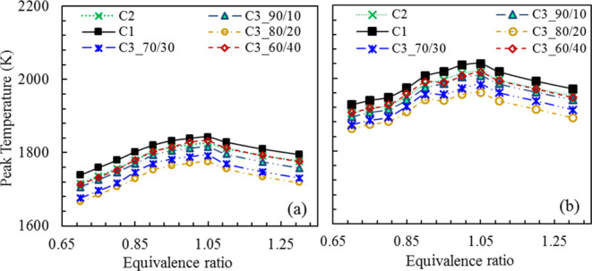
Peak temperature observed inside the combustor with equivalence ratios for (a) 25 and (b) 50 kW.
4.1.3. Peak Temperature
The effects of the bowl structure and the tangential air inlets on the peak temperature inside the combustor at different equivalence ratios are also shown in Figure 7. For the 25 kW thermal input, the peak temperature reduced from 1842 to 1824 K as a consequence of the bowl structure at the outlet. An additional ∼150 K reduction in peak temperature is observed due to the tangential injection of air up to 20%. However, increasing the tangential flow beyond 20% leads to a huge drop in the swirling effect of the total flow because of the low air supply to the swirler. This can be seen from the lower Rdil values for the cases of C3_70/30 and C3_60/40 as compared to the case of C3_80/20 (Figure 5). Therefore, a low drag of the fuel droplets to the radially outward regions is resulted, thus prohibiting a uniform mixing of evaporated fuel and air. The reduced mass flow through the central swirler reduces the velocity of the swirl flow; hence, the minimum momentum required for strong central recirculation was not achieved. For the case of C3_60/40, the tangential component is substantial and acts as axial co-flow air to the swirling flow of the reactants. This combustion methodology, therefore, resembles the conventional combustion process. It is observed that the peak temperature reduces with the use of hybrid swirl flow, and the case C3_80/20 is optimal in reducing the peak temperature.
With the increase in the thermal input, the air velocity at the exit of the swirler is increased due to the increased mass flow rate of the oxidizer. Hence, the recirculation zone is widened more and moved further upstream, as shown in the velocity vector plot of Figure 6b,c. The fuel thus evaporates close to the nozzle. However, the resultant axial velocity is increased for the 50 kW thermal input as compared to 25 kW. The reactants moved further downstream and stabilized the flame at the center of the combustor. The peak temperature is increased from 1842 to 2040 K with an increase in the thermal intensity for the C1 case. For the case of the 50 kW thermal input, 8 to 10% of higher flame temperatures are observed for all the cases (C1, C2, and C3) in the entire range of equivalence ratios.
4.2. Experimental Results
4.2.1. Flame Anchoring
Flame shapes can show the local turbulence caused by the hybrid swirl flow and the effect of the combustor shape. The corresponding flames observed in the experimental studies for stoichiometric condition and different orientations are shown in Figure 8. Figure 8a shows the flame generated with the hybrid swirl flow without the combustor top and cylinders. The combined swirling air with central fuel spray of a 45° solid cone angle produces a V-shaped flame with a lot of turbulence near the flame boundary being observed. The open combustion also helps in understanding the flame diffusion under the atmospheric condition. The corresponding flame length and flame width were observed to be ∼42 and ∼31 cm, respectively. The flame was predominantly of high sooting nature. Figure 8b–d shows the flames observed for the cases 1, 2, and 3, respectively, for a stoichiometric mixture with a thermal input of 25 kW. With the addition of the central combustor, the flame is compressed transversely and the flame height increases to ∼47 cm, as shown in Figure 8b. The insulation provided from the glass wool heats up the wall, which helps in a more distributive combustion zone. However, the confinement increases the axial velocity, and a more cylindrical flame is observed. The bowl-shaped outlet is further added to enhance the recirculation and maintain the uniform reaction zone in the combustor, as shown in Figure 8c. The flame sooting behavior at the outlet is observed to decrease significantly. The flame height is reduced to ∼37 cm with the red flame still visible from the outlet. This observation has an additional downward trend with the supply of the tangential air supply. Figure 8d shows the flame with the air split ratio for the case C3_80/20. The flame is detected to stabilize well within the combustor, and the fluctuations of disturbances inside the combustor are observed to reduce. The peripheral velocity from the tangential ports extends the combustible mixture to the dome at the outlet. This helps in increasing the distributiveness of the combustor, which was radially dominant for the cases C1 and C2 because of the conical fuel spray injection.
Figure 8.
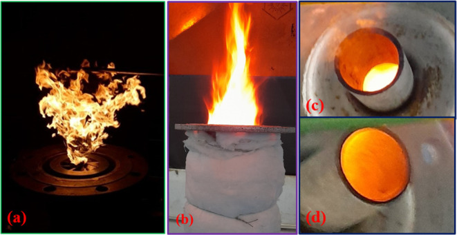
Experimental images of (a) open air combustion, (b) combustion without an outer bowl, case C1, (c) combustion with only central air swirlers, case C2, and (d) hybrid swirl combustion, case C3, for stoichiometric conditions.
4.2.2. Temperature Measurements
Radial temperature measurements are taken to understand the propagation and distribution of the reaction zone, as shown in Figures 9 and 10. Temperature readings at different radial locations, at axial locations of 15 and 25 cm downstream from the fuel nozzle, are taken with S-type thermocouples for a duration of ∼20 s to obtain the average temperature reading and reduce the effect of a moderately large response time of thermocouples (∼0.3 s). Figures 9 and 10 also show the numerical computation of the temperature at the axial location, which indicates a qualitative prediction. The temperature increases axially for both thermal input conditions that suggest that stabilization of flames occurs majorly at downstream locations. The increase in temperature for 25 kW is higher than that for the 50 kW. The high-temperature region is observed at radially outward, downstream locations due to the delay in forming a flammable mixture caused by the fuel jet momentum and swirling velocity of air. For the higher thermal input conditions, the average temperature increases, and thus, higher temperature zones are observed both radially and axially. Correspondingly, the increase in the thermal intensity causes the reaction zone to stabilize at a downstream location. Temperature differences of ∼700–900 and ∼900–1100 K are observed between the walls and the axis of the combustor for the thermal inputs of 25 and 50 kW, respectively, for the hybrid swirl case and stoichiometric mixture. The temperature gradient is observed to be steeper in the radial direction in the experiments as compared to the numerical computations. This is due to the perfect adiabatic condition assumption in the simulations which was not completely achieved in the experiments. A lower peak temperature is also observed numerically which could be limited due to the inability of the turbulent and β-PDF modeling to capture all scales of eddies and chemistry accurately.
Figure 9.
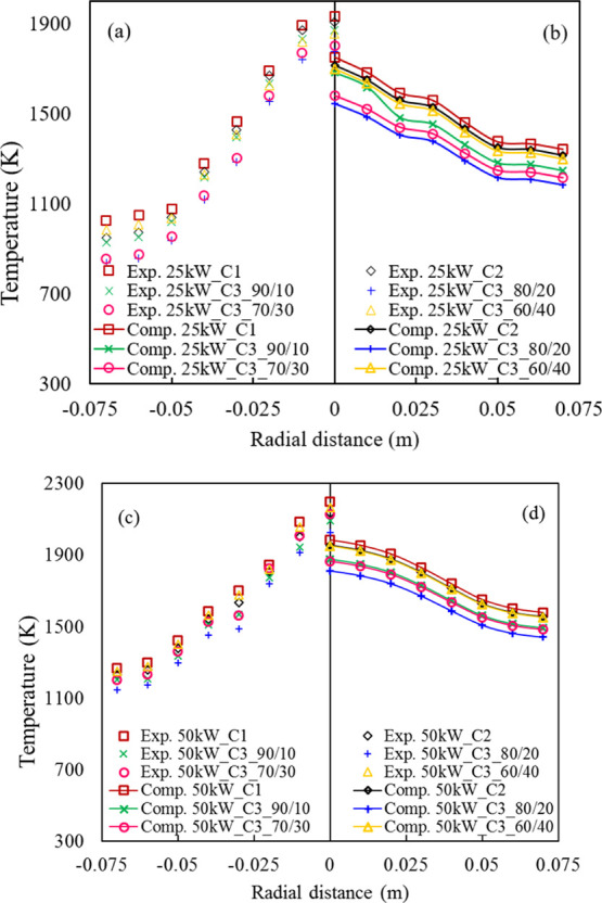
Experimental (only symbols) and numerical (solid lines with symbols) temperature variation along the radial direction at an axial location of 15 cm from the fuel nozzle for the (a,b) 25 kW thermal input and (c,d) 50 kW and stoichiometric mixture.
Figure 10.
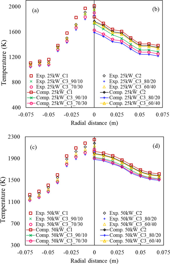
Experimental (only symbols) and numerical (solid lines with symbols) temperature variation along the radial direction at an axial location of 25 cm from the fuel nozzle for the (a,b) 25 kW thermal input and (c,d) 50 kW and stoichiometric mixture.
4.2.3. CO and NOx Emissions
Figures 11 and 12 show the variation of CO and NO emissions, respectively, observed at the exit of the combustor for the three swirl flow cases. The gas emission analyzer is kept near the exit of the combustor. The tangential air inlets and the bowl effect have a positive impact in curbing the CO and NO emissions owing to the increase in combustion rate. The secondary burning of the unburned hydrocarbons helps in reducing the CO emissions at the outlet despite the decrease in temperature, which has a countering effect on CO formation. The CO formation reduces for all cases with the mixture going from the lean side to the near stoichiometric mixture due to a corresponding increase in the conversion of CO to CO2 at high temperatures. The minimum CO formation is observed for an equivalence ratio of 1.05. The CO emission reduces from 138 to 125 ppm with the bowl recirculation and 125 to 99 ppm with the hybrid swirl (C3_80/20) for the stoichiometric mixture. A similar reduction in NO emissions is also observed with the adoption of the bowl effect and the hybrid swirl methodology. The hybrid swirl enlarges the reaction zone which reduces the peak temperature in the combustor. The effects of the bowl outlet and tangential air inlets in controlling the CO and NO emissions are more prominent for the lower thermal input case as compared to the higher thermal input case. For the thermal input of 50 kW, the density of the reactants is higher with higher recirculation observed inside the combustor. This inhibits the flow characteristics to develop properly because of the dome-shaped outlet and the hybrid inlet conditions.
Figure 11.
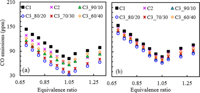
Variations of CO emissions with equivalence ratio for (a) 25 and (b) 50 kW.
Figure 12.
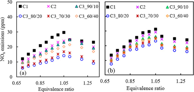
Variations of NOx emissions with equivalence ratio for (a) 25 and (b) 50 kW.
Total NOx emission is primarily produced from the thermal NOx pathway, and thermal NOx formation is in direct relation with the combustor temperature. The NO mass fraction is primarily the major component of total NOx formation. The thermal NO is formed from the Zeldovich mechanism that is shown as follows
| R1 |
| R2 |
| R3 |
The NO formation depends upon the availability of species N [RR2, RR3]. The concentration of N atoms is dependent on temperature since sufficiently large energy is required to react with N2 molecules, which is primarily an inert gas at room temperature. Therefore, combustor peak temperature plays a crucial role in the NOx formation. Hence, controlling the temperature through the hybrid swirl is observed to be an effective method in curbing the NOx emissions. NOx emissions are reduced by 6 ppm from the bowl effect and 10 ppm further with the hybrid swirl (C3_80/20) for the stoichiometric mixture and 25 kW thermal input. The NOx emissions, however, increase with the mixture going from lean to stoichiometric conditions and then reduce again for rich conditions. This is due to the direct correlation of the temperature variation across the equivalence ratio. With an increase in the thermal input from 25 to 50 kW, a larger magnitude of CO and NOx emissions is observed for all cases of C1, C2, and C3 (Figures 11b and 12b), and the behavior of variations remains the same.
5. Conclusions
In the present study, a novel hybrid swirl combustor is designed to achieve distributive combustion for moderate thermal inputs of 25 and 50 kW. Initially, CFD studies were carried out to find the optimal geometry to achieve large internal recirculation because of the bowl and swirl effect. Low uniform temperature and low emission characteristics were observed. Further studies suggest that supplying a fraction of air through tangential air inlets helps in diverging the flammable zone to the near-wall region and allows longer residence time to recirculate effectively. The tangential airflow extends the recirculation zone in the longitudinal direction, whereas the swirler distributes the reaction zone radially. This reduces the peak temperature inside the combustor. Three different cases are studied to analyze the effect of the bowl curvature and tangential airflow inside the combustor. It is observed that for the case of C3_80/20, where 80% of the airflow rate is through the swirlers and the rest 20% is through the tangential inlets, the peak temperature and emissions are reduced by the largest margin. Experiments are carried out with the optimal geometry identified for different equivalence ratios and thermal inputs. The numerical computations can mimic the experimental results qualitatively. The NOx and CO emissions are below 30 and 150 ppm, respectively, for all conditions. It is imperative to carry out a scaling analysis for such a configuration to understand the working under different power output conditions. The primary objective of this manuscript is, however, to test the hypothesis which is as follows: a hybrid air injection scheme works better in reducing the emissions and achieving a uniform combustion zone. Therefore, a detailed scaling analysis need to be carried out separately.
Acknowledgments
The authors (S.M., S.K.D., and V.M.R.) would like to acknowledge the funding received for this work from the Science and Engineering Research Board (SERB) of India (grant no. CRG/2019/005882).
Author Contributions
S.M.: conceptualization, methodology, investigation, software, and writing―original draft preparation. R.A.: investigation and writing―reviewing and editing. S.K.: writing―reviewing and editing. S.K.D.: supervision. V.M.R.: conceptualization, investigation, writing―reviewing and editing, supervision, and project administration.
The authors declare no competing financial interest.
References
- Wünning J. A.; Wünning J. G. Flameless Oxidation To Reduce Thermal No-Formation. Prog. Energy Combust. Sci. 1997, 23, 81–94. 10.1016/s0360-1285(97)00006-3. [DOI] [Google Scholar]
- de Joannon M.; Cavaliere A.; Faravelli T.; Ranzi E.; Sabia P.; Tregrossi A. Analysis of Process Parameters for Steady Operations in Methane Mild Combustion Technology. Proc. Combust. Inst. 2005, 30, 2605–2612. 10.1016/j.proci.2004.08.190. [DOI] [Google Scholar]
- Dally B. B.; Riesmeier E.; Peters N. Effect of Fuel Mixture on Moderate and Intense Low Oxygen Dilution Combustion. Combust. Flame 2004, 137, 418–431. 10.1016/j.combustflame.2004.02.011. [DOI] [Google Scholar]
- Li P.; Wang F.; Mi J.; Dally B. B.; Mei Z. MILD Combustion under Different Premixing Patterns and Characteristics of the Reaction Regime. Energy Fuel. 2014, 28, 2211–2226. 10.1021/ef402357t. [DOI] [Google Scholar]
- Sabia P.; Lubrano Lavadera M.; Giudicianni P.; Sorrentino G.; Ragucci R.; de Joannon M. CO2 and H2O Effect on Propane Auto-Ignition Delay Times under Mild Combustion Operative Conditions. Combust. Flame 2015, 162, 533–543. 10.1016/j.combustflame.2014.08.009. [DOI] [Google Scholar]
- De Joannon M.; Cavaliere A.; Donnarumma R.; Ragucci R. Dependence of Autoignition Delay on Oxygen Concentration in Mild Combustion of High Molecular Weight Paraffin. Proc. Combust. Inst. 2002, 29, 1139–1146. 10.1016/s1540-7489(02)80144-4. [DOI] [Google Scholar]
- de Joannon M.; Matarazzo A.; Sabia P.; Cavaliere A. Mild Combustion in Homogeneous Charge Diffusion Ignition (HCDI) Regime. Proc. Combust. Inst. 2007, 31, 3409–3416. 10.1016/j.proci.2006.07.039. [DOI] [Google Scholar]
- Medwell P. R.; Dally B. B. Effect of Fuel Composition on Jet Flames in a Heated and Diluted Oxidant Stream. Combust. Flame 2012, 159, 3138–3145. 10.1016/j.combustflame.2012.04.012. [DOI] [Google Scholar]
- Kumar S.; Paul P. J.; Mukunda H. S. Investigations of the Scaling Criteria for a Mild Combustion Burner. Proc. Combust. Inst. 2005, 30, 2613–2621. 10.1016/j.proci.2004.07.045. [DOI] [Google Scholar]
- Khalil A. E. E.; Gupta A. K. Distributed Swirl Combustion for Gas Turbine Application. Appl. Energy 2011, 88, 4898–4907. 10.1016/j.apenergy.2011.06.051. [DOI] [Google Scholar]
- Gupta A.High Temperature Air Combustion Technology-Invited Review. 39th AIAA/ASME/SAE/ASEE Joint Propulsion Conference and Exhibit, 2003.
- Arghode V. K.; Khalil A. E. E.; Gupta A. K. Fuel Dilution and Liquid Fuel Operational Effects on Ultra-High Thermal Intensity Distributed Combustor. Appl. Energy 2012, 95, 132–138. 10.1016/j.apenergy.2012.02.020. [DOI] [Google Scholar]
- Arghode V. K.; Gupta A. K. Development of High Intensity CDC Combustor for Gas Turbine Engines. Appl. Energy 2011, 88, 963–973. 10.1016/j.apenergy.2010.07.038. [DOI] [Google Scholar]
- Khalil A. E. E.; Arghode V. K.; Gupta A. K. Novel Mixing for Ultra-High Thermal Intensity Distributed Combustion. Appl. Energy 2013, 105, 327–334. 10.1016/j.apenergy.2012.12.071. [DOI] [Google Scholar]
- Derudi M.; Rota R. Experimental Study of the Mild Combustion of Liquid Hydrocarbons. Proc. Combust. Inst. 2011, 33, 3325–3332. 10.1016/j.proci.2010.06.120. [DOI] [Google Scholar]
- Mahendra Reddy V.; Sawant D.; Trivedi D.; Kumar S. Studies on a Liquid Fuel Based Two Stage Flameless Combustor. Proc. Combust. Inst. 2013, 34, 3319–3326. 10.1016/j.proci.2012.06.028. [DOI] [Google Scholar]
- Reddy V. M.; Katoch A.; Roberts W. L.; Kumar S. Experimental and Numerical Analysis for High Intensity Swirl Based Ultra-Low Emission Flameless Combustor Operating with Liquid Fuels. Proc. Combust. Inst. 2015, 35, 3581–3589. 10.1016/j.proci.2014.05.070. [DOI] [Google Scholar]
- Sharma S.; Singh P.; Gupta A.; Chowdhury A.; Khandelwal B.; Kumar S. Distributed combustion mode in a can-type gas turbine combustor - A numerical and experimental study. Appl. Energy 2020, 277, 115573. 10.1016/j.apenergy.2020.115573. [DOI] [Google Scholar]
- Huang M.; Xiao Y.; Zhang Z.; Shao W.; Xiong Y.; Liu Y.; Liu Z.; Lei F. Effect of Air/fuel Nozzle Arrangement on the MILD Combustion of Syngas. Appl. Therm. Eng. 2015, 87, 200–208. 10.1016/j.applthermaleng.2015.04.076. [DOI] [Google Scholar]
- Sung Y.; Choi G. Non-Intrusive Optical Diagnostics of Co- and Counter-Swirling Flames in a Dual Swirl Pulverized Coal Combustion Burner. Fuel 2016, 174, 76–88. 10.1016/j.fuel.2016.01.011. [DOI] [Google Scholar]
- Weigand P.; Meier W.; Duan X. R.; Stricker W.; Aigner M. Investigations of swirl flames in a gas turbine model combustor. Combust. Flame 2006, 144, 205–224. 10.1016/j.combustflame.2005.07.010. [DOI] [Google Scholar]
- Chen Z. X.; Langella I.; Swaminathan N.; Stöhr M.; Meier W.; Kolla H. Large Eddy Simulation of a Dual Swirl Gas Turbine Combustor: Flame/flow Structures and Stabilisation under Thermoacoustically Stable and Unstable Conditions. Combust. Flame 2019, 203, 279–300. 10.1016/j.combustflame.2019.02.013. [DOI] [Google Scholar]
- Chen Z. X.; Swaminathan N.; Stöhr M.; Meier W. Interaction between Self-Excited Oscillations and Fuel-Air Mixing in a Dual Swirl Combustor. Proc. Combust. Inst. 2019, 37, 2325–2333. 10.1016/j.proci.2018.08.042. [DOI] [Google Scholar]
- Yang S.; Zhang C.; Lin Y.; Xue X.; Gan X. Experimental Investigation of the Ignition Process in a Separated Dual-Swirl Spray Flame. Combust. Flame 2020, 219, 161–177. 10.1016/j.combustflame.2020.05.010. [DOI] [Google Scholar]
- Bulat G.; Jones W. P.; Navarro-Martinez S. Large Eddy Simulations of Isothermal Confined Swirling Flow in an Industrial Gas-Turbine. Int. J. Heat Fluid Flow 2015, 51, 50–64. 10.1016/j.ijheatfluidflow.2014.10.028. [DOI] [Google Scholar]
- Chong C. T.; Lam S. S.; Hochgreb S. Effect of Mixture Flow Stratification on Premixed Flame Structure and Emissions under Counter-Rotating Swirl Burner Configuration. Appl. Therm. Eng. 2016, 105, 905–912. 10.1016/j.applthermaleng.2016.03.164. [DOI] [Google Scholar]
- Reddy V. M.; Biswas P.; Garg P.; Kumar S. Combustion Characteristics of Biodiesel Fuel in High Recirculation Conditions. Fuel Process. Technol. 2014, 118, 310–317. 10.1016/j.fuproc.2013.10.004. [DOI] [Google Scholar]
- Reddy V. M.; Trivedi D.; Sawant D.; Kumar S. Investigations on Emission Characteristics of Liquid Fuels in a Swirl Combustor. Combust. Sci. Technol. 2015, 187, 469–488. 10.1080/00102202.2014.956098. [DOI] [Google Scholar]
- Ahn B.; Kim K. T. Effect of Counter- and Co-Swirl on Low-Frequency Combustion Instabilities of Jet A-1 Spray Flames. J. Eng. Gas Turbines Power. 2022, 144, 1–7. 10.1115/1.4055354. [DOI] [Google Scholar]
- Bai N. J.; Fan W. J.; Zhang R. C.; Zou Z. P.; Zhang C. X.; Yan P. L. Numerical Investigation into the Structural Characteristics of a Hydrogen Dual-Swirl Combustor with Slight Temperature Rise Combustion. Int. J. Hydrogen Energy 2021, 46, 22646–22658. 10.1016/j.ijhydene.2021.04.075. [DOI] [Google Scholar]
- Weber R.; Smart J. P.; Kamp W. On the (MILD) Combustion of Gaseous, Liquid, and Solid Fuels in High Temperature Preheated Air. Proc. Combust. Inst. 2005, 30, 2623–2629. 10.1016/j.proci.2004.08.101. [DOI] [Google Scholar]
- Hadef R.; Lenze B. Effects of Co- and Counter-Swirl on the Droplet Characteristics in a Spray Flame. Chem. Eng. Process.: Process Intensif. 2008, 47, 2209–2217. 10.1016/j.cep.2007.11.017. [DOI] [Google Scholar]
- Huang D.; Xu J.; Chen R.; Meng H. Large Eddy Simulations of Turbulent Combustion of Kerosene-Air in a Dual Swirl Gas Turbine Model Combustor at High Pressures. Fuel 2020, 282, 118820. 10.1016/j.fuel.2020.118820. [DOI] [Google Scholar]
- Sharma S.; Chowdhury A.; Kumar S. A Novel Air Injection Scheme to Achieve MILD Combustion in a Can-Type Gas Turbine Combustor. Energy 2020, 194, 116819. 10.1016/j.energy.2019.116819. [DOI] [Google Scholar]
- Sharma S.; Pingulkar H.; Chowdhury A.; Kumar S. A New Emission Reduction Approach in MILD Combustion through Asymmetric Fuel Injection. Combust. Flame 2018, 193, 61–75. 10.1016/j.combustflame.2018.03.008. [DOI] [Google Scholar]
- Cheong K. P.; Wang G.; Wang B.; Zhu R.; Ren W.; Mi J. Stability and Emission Characteristics of Nonpremixed MILD Combustion from a Parallel-Jet Burner in a Cylindrical Furnace. Energy 2019, 170, 1181–1190. 10.1016/j.energy.2018.12.146. [DOI] [Google Scholar]
- Arghode V. K.; Gupta A. K. Role of Thermal Intensity on Operational Characteristics of Ultra-Low Emission Colorless Distributed Combustion. Appl. Energy 2013, 111, 930–956. 10.1016/j.apenergy.2013.06.039. [DOI] [Google Scholar]
- Stöhr M.; Yin Z.; Meier W. Interaction between Velocity Fluctuations and Equivalence Ratio Fluctuations during Thermoacoustic Oscillations in a Partially Premixed Swirl Combustor. Proc. Combust. Inst. 2017, 36, 3907–3915. 10.1016/j.proci.2016.06.084. [DOI] [Google Scholar]
- Chinnici A.; Nathan G. J.; Dally B. B. An Experimental Study of the Stability and Performance Characteristics of a Hybrid Solar Receiver Combustor Operated in the MILD Combustion Regime. Proc. Combust. Inst. 2019, 37, 5687–5695. 10.1016/j.proci.2018.05.099. [DOI] [Google Scholar]
- Mohapatra S.; Garnayak S.; Lee B. J.; Elbaz A. M.; Roberts W. L.; Dash S. K.; Reddy V. M. Numerical and Chemical Kinetic Analysis to Evaluate the Effect of Steam Dilution and Pressure on Combustion of N-Dodecane in a Swirling Flow Environment. Fuel 2021, 288, 119710. 10.1016/j.fuel.2020.119710. [DOI] [Google Scholar]
- Gupta A. K.; Lilley D. G.; Syred N.. Swirl Flows; Abacus Press: Kent, England, 1984. [Google Scholar]


