Abstract
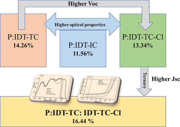
We have designed a new medium bandgap non-fullerene small-molecule acceptor consisting of an IDT donor core flanked with 2-(6-oxo-5,6-dihydro-4H-cyclopenta[c]-thiophene-4-ylidene) malononitrile (TC) acceptor terminal groups (IDT-TC) and compared its optical and electrochemical properties with the IDT-IC acceptor. IDT-TC showed an absorption profile from 300 to 760 nm, and it has an optical bandgap of 1.65 eV and HOMO and LUMO energy levels of −5.55 and −3.83 eV, respectively. In contrast to IDT-IC, IDT-TC has an upshifted LUMO energy level, which is advantageous for achieving high open-circuit voltage. Moreover, IDT-TC showed higher crystallinity and high electron mobility than IDT-IC. Using a wide bandgap D–A copolymer P as the donor, we compared the photovoltaic performance of IDT-TC, IDT-IC, and IDT-IC-Cl nonfullerene acceptors (NFAs). Polymer solar cells (PSCs) using P: IDT-TC, P: IDT-IC, and P:IDT-IC-Cl active layers achieved a power conversion efficiency (PCE) of 14.26, 11.56, and 13.34%, respectively. As the absorption profiles of IDT-IC-Cl and IDT-TC are complementary to each other, we have incorporated IDT-TC as the guest acceptor in the P: IDT-IC-Cl active layer to fabricate the ternary (P:IDT-TC: IDT-IC-Cl) PSC, demonstrating a PCE of 16.44%, which is significantly higher than that of the binary BHJ devices. The improvement in PCE for ternary PSCs is attributed to the efficient exploitation of excitons via energy transfer from IDT-TC to IDT-IC-Cl, suitable nanoscale phase separation, compact stacking distance, and more evenly distributed charge transport.
1. Introduction
The polymer solar cells (PSCs) are seen to be promising after developing the concept of bulk heterojunction (BHJ)1 due to their low cost and large area, semitransparent nature, and environmentally friendly photovoltaic technology using solution-processed roll-to-roll printing techniques.2−8 The development of the novel Y6 small-molecule acceptor (SMA), reported by Zou et al., in 2019, realized a power conversion efficiency (PCE) of 15.7% for PSCs.9 An improved PCE of 15.98% has been achieved using modified Y6, that is, N3 SMA,10 and recently, over 17% of as-cast PSCs have also been reported.11 Currently, the PCE of PSCs has reached 18–19% for the single junction PSCs based on narrow bandgap SMAs via the use of additives and interface engineering.12−16
Furthermore, besides the narrow bandgap SMAs, medium bandgap SMAs (i.e., optical bandgap in the range 1.6–1.8 eV) have also been designed and used considerably for PSCs.17−25 The photons below the wavelength range of 300–800 nm may be fully harvested by the PSCs, which are made of a medium bandgap SMA and a wide bandgap polymer donor. A high open-circuit voltage (VOC) produced by SMAs’ upshifted LUMO energy level makes them the ideal front subcells for tandem solar cells.26−29 In order to achieve a PCE of 10.08% with a high VOC of 0.98 V, Chen et al. created a medium bandgap SMA F-M with an optical bandgap of 1.65 eV and employed it as an acceptor along with copolymer donor PBDB-T.30 When the PBDB-T: F-M active layer was used in the front subcell, the tandem solar cells realized a record PCE of 17.36%.31 Ding et al. have synthesized a medium bandgap SMA, IBCT, which exhibits a bandgap of 1.65 eV. In order to achieve an overall PCE of 11.26% with a high VOC of 1.02 V, the medium bandgap IBCT is used as an acceptor together with a wide bandgap polymer L1. In tandem solar cells, they have also employed the L1:IBCT active layer as the front subcell and have attained a PCE of 15.25%.32 A PCE of 18.71% was obtained by Huang et al. using a medium bandgap SMA in the front cell of the tandem PSCs.33 While using a wide bandgap polymer donor and narrow bandgap SMA, the binary BHJ active layer only absorbs photons in the shorter and longer wavelength regions, thereby limiting PSCs’ light-harvesting ability and also the value of JSC of the PSCs.34 To broaden the absorption profile from 300 to 900 nm and improve the exciton generation and morphology of the BHJ active layer, the ternary concept has been developed by incorporating either a second acceptor or donor as a guest component material into the host binary BHJ active layer.35−39 This notion is useful for optimizing the light-harvesting, exciton dissociation, and charge transport in the active ternary layers.40 Furthermore, ternary PSCs retain the simple fabrication technique utilized for binary BHJ PSCs and alter the energy level matching of the D/A interface, which is also required to achieve a high PCE. The addition of a third material to a ternary BHJ active layer can raise the VOC, expand the absorption profile, and improve photon harvesting, all of which increase the short-circuit current (JSC). Additionally, the fill factor (FF) of the PSCs is improved, and the charge carrier transit is improved by an appropriate cascade energy level structure, which also suppresses the recombination processes.24 In some cases, the third component can act as an additional energy donor by forming an efficient energy transfer channel with the host binary system and improving the efficiency of photogenerated exciton generation.41−43 This occurs when the third component’s PL spectrum overlaps with the host’s (donor or acceptor) absorption spectra.
In order to create high-performing SMAs, terminal group engineering is essential. The LUMO levels of A-D-A SMAs and, consequently, the VOC values can be significantly influenced by terminal units according to predictions made by researchers.44−47 Additionally, since the molecular packing of A-D-A SMAs is mostly dependent on the terminal group stacking, tightly packed end-groups speed up the electron transport. 2-(6-Oxo-5,6-dihydro-4H-cyclopenta[c]-thiophene-4-ylidene)malononitrile denoted as TC is a potential end-group for the designing of A–D–A acceptors due to its strong light harvesting from the electron delocalization and reasonable charge transport originating from the strong intermolecular S–S interactions.48,49 Zou et al. have created an A-DA′D–A NFA Y10 consisting of a weak TPBT-based core and two electron-accepting units of TC, and the PSCs based on this non-fullerene acceptor (NFA) demonstrate a PCE of 13.46%.50 Xie et al. designed an NFA of ITCPTC with the thiophene fused ending group and achieved a PCE of 11.8% with an FF of 0.751, which is 20% higher than for the ITIC-based counterpart.51 An outstanding VOC of 1.10 V and an efficiency of about 7.34% were attained by Gao et al. when they combined the donor, a conjugated polymer PBDB-T, with a twisted NFA acceptor with thiophene fused terminal groups.52
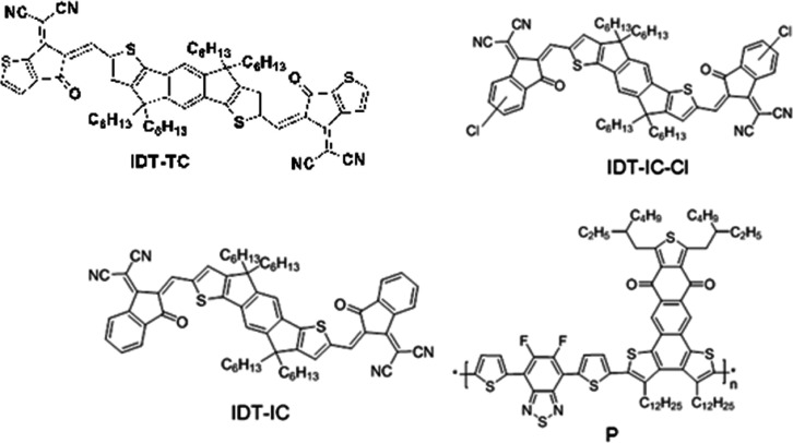
A novel A–D–A SMA, designated IDT-TC, has been created and synthesized using an IDT donor core and TC acceptor terminals. IDT-TC displayed an absorption profile between 300 and 760 nm (optical bandgap of 1.65 eV) with HOMO/LUMO energy levels of −5.55/–3.83 eV. We have compared the photovoltaic performance of IDT-TC with two other non-fullerenes having the same donor core as IDT-TC with different terminal units, that is, IDT-IC and IDT-IC-Cl.53 The high-lying LUMO of IDT-TC is beneficial for attaining VOC for the PSCs. We have used a wide bandgap D–A1–D–A2 conjugated polymer P as a donor with donor thiophene (D) and fluorinated benzothiadiazole (A1) and anthra[1,2-b:4,3,b′:6,7-c″]trithiophene-8.12-dione (A2).54 In Chart 1, the chemical structures of IDT-TC, IDT-IC, IDT-IC-Cl, and P are shown. Our fabrication of binary BHJ PSCs resulted in a greater overall PCE of 14.26% with a VOC of 1.04 V than the PSC based on the IDT-IC equivalent (12.15%). Using P as the donor and narrow bandgap IDT-IC-Cl as the acceptor, we also designed PSCs, achieving an overall PCE of 13.35% with a VOC of 0.86 V. In order to create the ternary (P:IDT-TC: IDT-IC-Cl) PSCs, we added a little amount of IDT-TC as a third component to the binary P: IDT-IC-Cl. We obtained a PCE of 16.44% with a VOC of 0.96 V.
Chart 1. Chemical Structure of IDT-TC, IDT-IC, IDT-IC-Cl, and P.
2. Experimental Section
2.1. Materials
All of the reagents and chemicals were purchased from Aldrich, Acros, TCI and used without further purification. Toluene was dried and purified by fractional distillation over sodium/benzophenone under argon. The intermediate compounds and their characterizations are described in Supporting Information.
2.2. Synthesis of 2,2′-((5Z,5′Z)-5,5′-((4,4,9,9-Tetrahexyl-4,9-dihydro-s-indaceno[1,2-b:5,6-b′]dithiophene-2,7-diyl)bis(methanylylidene))bis(6-oxo-5,6-dihydro-4H-cyclopenta[b]thiophene-5,4-diylidene))dimalononitrile (IDT-TC)
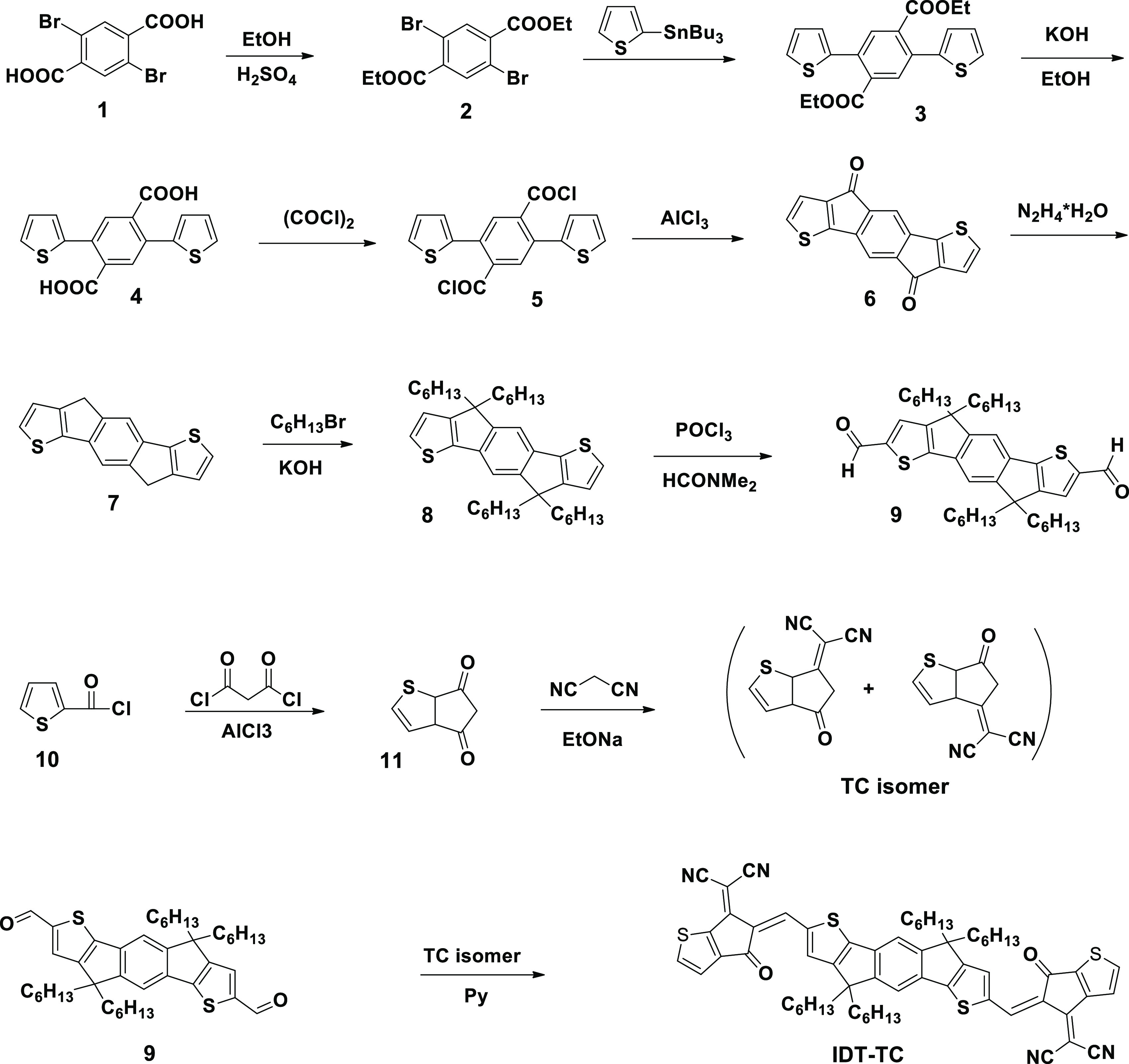
The synthesis of IDT-TC is shown in Scheme 1. Pyridine (1.3 mL) was added to a solution of dialdehyde 9 (0.13, 0.2 mmol) and indanon TC (0.40 g, 0.4 mol) in chloroform (65 mL) in an argon atmosphere, and then, the mixture was boiled for 25 h. After cooling to room temperature, the mixture was poured into methanol, and the precipitate was filtered and purified by column chromatography using hexane/dichloromethane (1:1.2/v) as an eluent. The yield of the target product is 102 mg, 50%. 1H NMR (500 MHz CDCl3) (Figures S1 and S2): δ (ppm) 8.75(s),89.74(s)-2H; 7.99 (AB), 7.90(d), 7.47(d)-4H; 7.68(s)-2H; 7.58(s)-2H; 2.20–1.90 (8H); 1.30–1/00(24H);9.95–0.65(2H). 13CNMR (100 MHz, CDCl3): δ (ppm) 182.45, 180.77, 158.78, 157.44, 156.98, 156.19, 152.44, 152.27, 150.19, 148.45, 139.91, 139.24, 137.67, 136.92, 136.53, 124.53, 124.18, 123.56, 121.29, 115.69, 114.46, 114.37, 114.01, 113.79, 68.91, 67.31, 54.30,39.09, 31.53, 29.56.24.32,22.56, 13.99. Elem. Anal. Calcd for C62H62N4O2S4: C, 72.76; H, 6.11; N, 5.47; S, 12.53. Found: C, 72.49; H, 6.00; N, 5.29; S, 12.21%.
Scheme 1. Synthesis Route for IDT-TC.
2.3. Device Fabrication and Characterization
The PSCs with the structure of ITO/PEODT/PSS/active layer/PFN/Al were fabricated to evaluate the photovoltaic performance of IDT-TC, IDT-IC, and IDT-IC-Cl as acceptors and P as the donor. The detailed fabrication of PSCs is described in Supporting Information.
3. Results and Discussion
3.1. Synthesis and Characterization of IDT-TC
Scheme 1 describes the synthesis process of IDT-TC. Experimental details to synthesize the intermediate compounds are described in the Supporting Information. The target NFA 2,2′-((5Z,5′Z)-5,5′-((4,4,9,9-tetrahexyl-4,9-dihydro-s-indaceno[ 1,2-b:5,6-b′] dithiophene-2,7-diyl)bis(methanylylidene))bis(6-oxo-5,6-dihydro-4H-cyclopenta[b]thiophene-5,4-diylidene))dimalononitrile (IDT-TC) was synthesized through the Knoevenagel condensation reaction between dialdehyde 9 and TC with 50% yield. 1H NMR confirmed the composition and structure of all intermediates. The target product (IDT-TC) was characterized by 1H NMR, 13C NMR, and elemental analysis (Figures S1 and S2, Supporting Information). The elemental analysis is also summarized in the Supporting Information.
At room temperature, IDT-TC is highly soluble in common organic solvents like chloroform, toluene, and o-dichlorobenzene. With a breakdown temperature (Td, 5% weight loss) of 342 °C (Figure S3, Supporting Information), IDT-TC demonstrates outstanding thermal stability, which is advantageous for optoelectronic devices.
3.2. Optical and Electrochemical Properties
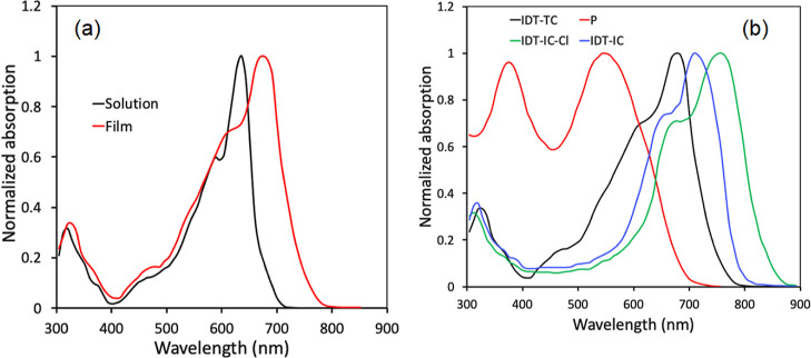
Figure 1a displays the normalized absorption spectra in a thin-film cast and diluted chloroform solution, and related results are reported in Table 1. IDT-TC displayed two distinct absorption bands in both solution and film, namely, 300–400 nm for the π–π* transition55 and 400–750 nm for the intramolecular charge transfer (ICT) between the central donor core and terminal acceptor units. The ICT peak in the thin-film absorption spectra is red-shifted (42 nm) in comparison to that in the solution, showing strong molecular backbone aggregations and—interactions in the solid state. The optical bandgap estimated from the onset of thin-film absorption spectra was about 1.65 eV. Figure 1b also displays the thin-film absorption spectra for IDT-IC, IDT-IC-Cl, and P. The absorption of IDT-TC, IDT-IC, and IDT-IC-Cl was complimentary to that of P, which is advantageous for a high value of JSC of the resultant PSCs via increasing the photon harvesting range from 300 to 900 nm for the ternary active layer.
Figure 1.
Normalized absorption spectra of IDT-IC in (a) dilute solution and film and (b) thin absorption spectra of IDT-TC, IDT-IC, IDT-IC-Cl, and P.
Table 1. Thermal, Optical, and Electrochemical Properties of IDT-IC.
| acceptor | T5% [°C] | λmax (sol) [nm] | λmax (film) [nm] | EHOMO [eV] | ELUMO [eV] | Egech [eV] | Egopt [eV] |
|---|---|---|---|---|---|---|---|
| IDT-TC | 342 | 635 (2.3 × 10⁵ M–1 cm–1)a | 674 | –5.57 | –3.81 | 1.73 | 1.65 |
Molar extinction coefficient.
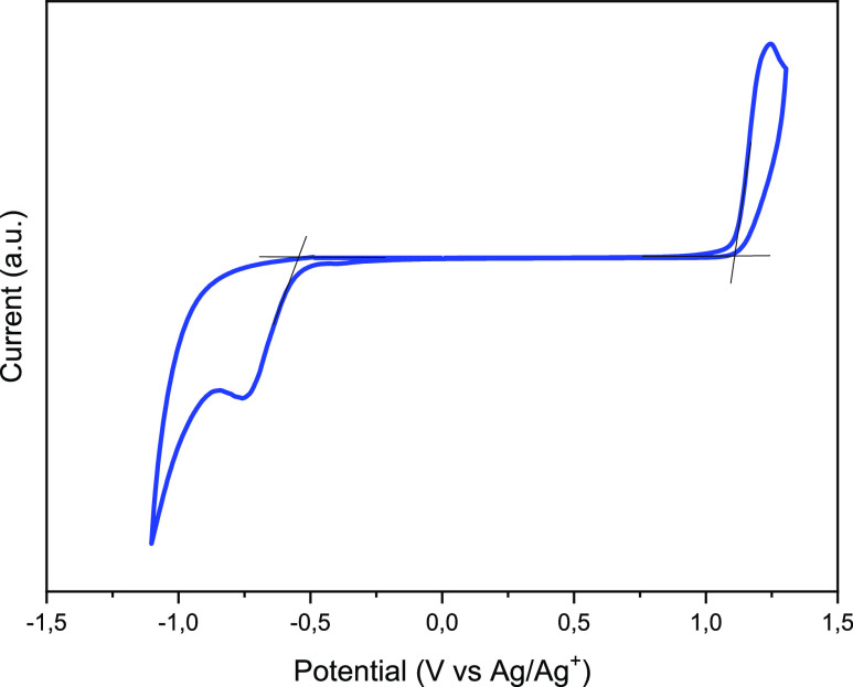
The HOMO and LUMO energy levels of IDT-TC were calculated via the electrochemical cyclic voltammetry (CV) technique, with Ag/AgNO3 as the reference electrode and FC/Fc+ couple as the internal reference (Figure 2). The CV curves for IDT-IC and IDT-IC-Cl are also shown in Figure S4 (Supporting Information). The measured EHOMO/ELUMO values of IDT-TC are −5.57 and −3.82 eV, respectively, whereas the EHOMO/ELUMO values of IDT-IC are about −5.60 and −3.94 eV, respectively.53 We observed that with the change in the terminal unit from IC to TC, the NFA’s LUMO energy level shifted up, while the HOMO energy levels remained almost unchanged. It has already been reported that the central donor unit mainly determines the HOMO of the A–D–A materials, and LUMO mainly depends upon the terminal acceptor unit. IDT-TC displayed blue-shifted absorption and an increased LUMO energy level in comparison to IDT-IC because thiophene has a weaker ability to donate electrons than phenyl, which reduces the ability of terminal units to withdraw electrons. This reduces the strength of the ICT effect and increases the HOMO of the resulting acceptor molecule.56,57 The IDT-high IC’s LUMO energy promotes the achievement of a greater open-circuit voltage.
Figure 2.
CV curve for IDT-TC.
3.3. Theoretical Simulations
To carry out the DFT calculation, computer models of IDT-TC and IDT-IC molecules were created, in which methyl ones replaced hexyl radicals. The geometry of these models in the equilibrium and transition states was estimated by the DFT/ωB97X-D3(BJ)/6-31G(d,p)++ method. Figures S5 and S6 (Supporting Information) demonstrate these findings. The models have an almost planar structure, the stability of which is ensured by forming intramolecular aromatic hydrogen bonds. HOMO and LUMO energies, HOMO and LUMO surfaces, and electrostatic potential were calculated using the DFT/MN15-L/6-31G(d,p)++ method (Figure 3 and Table 2). For both models, the HOMO surfaces are located on the fragment 4,9-dihydro-s-indaceno[1,2-b:5,6-b′]dithiophene; the HOMO values for both models are close. LUMO surfaces are also located on the side fragments—2-(2-methylene-3-oxo-2,3-dihydro-1H-inden-1-ylidene)malononitrile (IC) in the case of IDT-IC and 2-(5-methylene-6-oxo-5,6-dihydro-4H-cyclopenta[b]thiophen-4-ylidene)malononitrile (TC) in the case of IDT-TC. For IDT-TC, the LUMO value is higher, and the Eg value is greater than for IDT-IC. The negative values of the electrostatic potential are concentrated on the nitrogen atoms of the nitrile groups and the oxygen atoms of the carbonyl groups (Figure 4).
Figure 3.
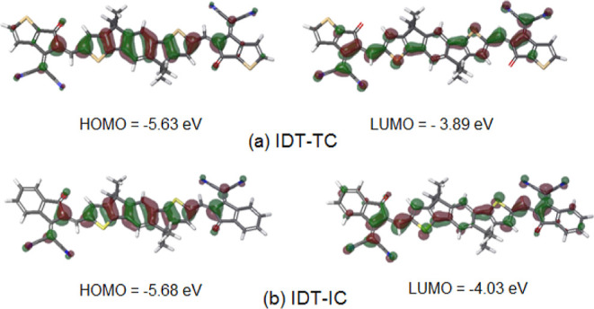
Molecular orbital surfaces of (a) IDT-TC and (b) IDT-IC calculated by the DFT/MN15-L/6-31G(d,p)++ method.
Table 2. HOMO and LUMO Energy Levels of IDT-TC and IDT-IC.
| material | HOMO (eV) | LUMO (eV) | Eg (eV) |
|---|---|---|---|
| IDT-TC, experimental data | –5.56 | –3.82 | 1.74 |
| IDT-TC, calculation by the DFT/MN15-L/6-31G(d,p)++ method | –5.63 | –3.89 | 1.74 |
| IDT-IC, calculation by the DFT/MN15-L/6-31G(d,p)++ method | –5.68 | –4.03 | 1.65 |
Figure 4.

Electrostatic potential surface for (a) IDT-TC and (b) IDT-IC calculated by the DFT/M15-L/6-31(d,p)++ method.
3.4. Mobility and Crystallinity
The electron mobilities of the pristine films made with IDT-TC and IDT-IC were also measured (Figure S7), and it was observed that IDT-TC had greater electron mobility (4.78 × 10⁻⁴ cm2/Vs) than IDT-IC (3.97 × 10⁻⁴ cm2/Vs). This difference is most likely attributable to better electron delocalization and stronger intermolecular forces through the formation of noncovalent S–S bonds, which facilitate electron transport.
We also compared the molecular ordering and crystallinity of IDT-TC with those of IDT-IC via the XRD patterns (Figure S8). It can be seen from this figure that both (100) and (010) correspond to lamellar stacking, and π–π stacking of IDT-TC was more substantial and sharper than that of IDT-IC, indicating a stronger crystallinity of IDT-TC. The enhancement of molecule crystallinity is beneficial for charge carrier mobility.
3.5. Photovoltaic Properties
We used the medium bandgap SMA IDT-TC as an acceptor and wide bandgap copolymer P as a donor to fabricate the binary BHJ PSCs. We also fabricated the PSCs using IDT-IC and IDT-IC-Cl as acceptors for comparison. In order to fabricate the ternary PSCs, we have incorporated IDT-TC as the second acceptor in the host P: IDT-IC-Cl binary BHJ active layer. The absorption spectra for IDT-TC, IDT-IC, IDT-IC-Cl, and P are shown in Figure 1b. These energy levels are shown in Figures 5 and 4b, respectively. The LUMO offsets [ΔELUMO (D/A)] for P/IDT-IC and P/IDT-IC-Cl are 0.23 and 0.38 eV, respectively. Figure S9 shows the photoluminescence (PL) spectra of pure P and its blend with either IDT-TC or IDT-IC-Cl in order to provide information regarding the electron transport from P to either of these materials. When excited at 540 nm, P displayed a significant PL peak at 698 nm, which was totally quenched for both P: IDT-TC and P: IDT-IC-Cl, suggesting efficient electron transport from P to either IDT-TC or IDT-IC-Cl in their respective D/A interfaces. The HOMO offsets [ΔEHOMO (D/A)] for IDT-TC/P and IDT-IC-Cl/P were 0.12 and 0.19 eV, respectively. As shown in Figure 6, we further investigated the PL spectra of pristine IDT-TC and IDT-IC-Cl as well as their P blends. The pristine IDT-TC and IDT-IC-Cl films showed strong PL peaks at 748 and 844 nm, respectively, when excited at their maximum absorption peak, which was completely quenched for their blends with P (the PL quenching efficiencies for IDT-IC:P and IDT-IC-Cl:P are about 92 and 95%), demonstrating efficient hole transfer from either IDT-TC or IDT-IC-Cl to P in their respective D/A interfaces, even the small ΔEHOMO (D/A), and this is observed in most of the non-fullerene PSCs.58−60
Figure 5.
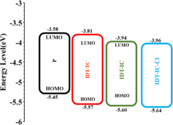
Energy level diagrams of IDT-TC, IDT-IC, IDT-IC-Cl, and P.
Figure 6.
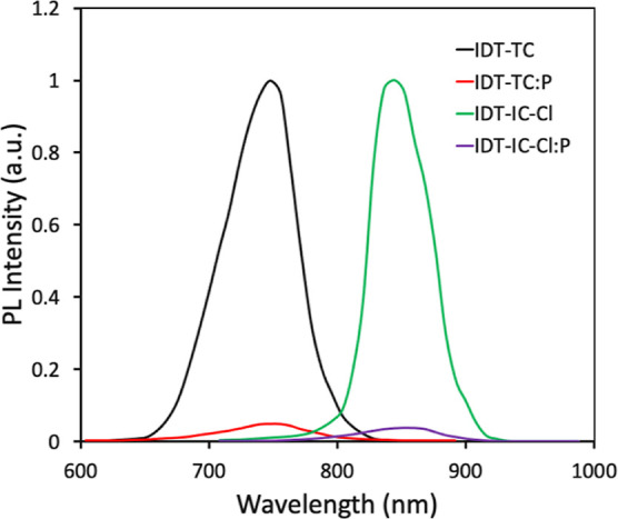
Thin-film PL spectra of pristine acceptors (IDT-TC and IDT-IC-Cl) and their blends with P.
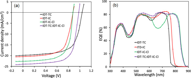
We have fabricated binary BHJ PSCs using P as the donor and IDT-TC, IDT-IC, and IDT-IC-Cl as the acceptors. By changing the weight ratio between the donor and acceptor, the photovoltaic performance was optimized. We observed that the PSCs with the best PCE had a D/A weight ratio of 1:1.2 (Table S1a–c, Supporting Information). The optimized PSC (1:1.2) was then treated with THF for 40 s in order to undergo solvent vapor annealing treatment (Table S2a–c, Supporting Information). Figure 7a shows the current–voltage characteristics of optimized PSCs under illumination (AM1.5 G, 100 mW/cm2), and Table 3 compiles associated photovoltaic data.
Figure 7.
(a) J–V characteristics under illumination (AM1.5 G, 100 mW cm–2) and (b) EQE spectra of the binary and ternary PSCs.
Table 3. Photovoltaic Data for the Binary and Ternary PSCs.
| active layer | JSC (mA/cm2) | VOC (V) | FF | PCE (%) |
|---|---|---|---|---|
| P:IDT-TC (1:1.2) | 19.88 (±0.21) (19.74)a | 1.04 | 0.69 (±0.014) | 14.26 (±0.11) (14.14)b |
| P:IDT-IC (1:1.2) | 20.52 (±0.13) (20.41)a | 0.88 | 0.64 (±0.012) | 11.56 (±0.14) (11.41)b |
| P:IDT-IC-Cl (1:1.2) | 22.64 (±0.11) (20.52)a | 0.88 | 0.67 (±0.011) | 13.34 (±0.11) (13.21)b |
| P:IDT-TC:IDT-IC-Cl (1:0.3:0.9) | 23.98 (±0.14) (23.83)a | 0.96 | 0.714 (±0.015) | 16.44 (±0.15) (16.21)b |
JSC value estimated from EQE spectra.
Average of eight identical devices.
Although the value of JSC is lowest for IDT-IC-based devices, the optimized binary BHJ PSCs based on IDT-TC showed a higher PCE of 14.26% to IDT-IC (11.56%) and IDT-IC-Cl (13.34%). This is because of the high values of VOC and FF. As the VOC is directly related to the energy difference between the HOMO of the donor and LUMO of the acceptor used in the BHJ active layer, the highest value of VOC for IDT-TC may be associated with its high-lying LUMO energy level as compared to either IDT-IC or IDT-IC-Cl. We recorded the PSCs’ external quantum efficiency (EQE) spectra in order to learn more about the variation in JSC values, as depicted in Figure 7b. For IDT-TC, IDT-IC, and IDT-IC-Cl-based devices, respectively, the JSC values derived from the integration of EQE spectra are 19.72, 20.39, and 22.47 mA/cm2.
3.6. Ternary Polymer Solar Cells
It is reported that the ternary approach has been the efficient method to improve the PCE of PSCs owing to enhanced light harvesting ability via energy transfer from the guest component to the host system60 and attained a PCE exceeding 19%.12,13 Various working principles such as charge transfer, energy transfer, and alloy model have been utilized to understand the enhancement in the PCE of ternary PSCs as compared to that of the binary counterpart.61−63
As shown in Figure 1b, the conjugated polymer P, IDT-TC, and ICT-IC-Cl exhibit the complementary absorption spectra with each other. The energy levels of these materials (Figure 5) also indicate that combination of these materials is also beneficial for ternary PSCs. The VOC of the IDT-TC-based PSC was relatively high compared to that of IDT-IC-Cl, whereas the value of JSC for IDT-IC-Cl was higher than that for IDT-TC; we fabricated the ternary PSCs via incorporating IDT-TC into the P: IDT-IC-Cl binary active layer. Moreover, the absorption profile of both the acceptors is complementary. The weight concentration of P is held constant, while the weight ratio between the two acceptors is changed from 0.1:1.1 to 0.4:0.8. Additionally, we maintained a total concentration of 14 mg/mL for each ternary blend, the same as for binary blends. We noticed that the best photovoltaic performance was achieved using the ternary active layer P:IDT-TC: IDT-IC-Cl (1:0.3:0.9) (Table S3, Supporting Information). The optimized ternary active layer was then subjected to solvent vapor annealing for 40 s as done for binary active layers. Table 3 contains the photovoltaic parameters that correspond to the J–V characteristics under illumination shown in Figure 7a. The PCE for the optimized ternary PSCs reached 16.44%, which is greater than the PCE for the binary PSCs. We also carried out EQE measurements of the ternary PSC in order to learn more about the advancement in the JSC value, as shown in Figure 7b. The P: IDT-IC-Cl binary PSC showed EQE spectra up to 890 nm with a value of around 670 nm, whereas the EQE spectra of the P: IDT-TC-based PSC are limited to 780 nm with high values of EQE in the 630–720 nm region. This region is greatly filled up with the addition of IDT-TC, which also results in a ternary PSC feature that is broader and more photoresponsive. The EQE spectral difference (ΔEQE) between ternary P: IDT-TC: IDT-IC-Cl and binary P: IDT-IC-Cl was also calculated and is shown in Figure S10 (Supporting Information). The ΔEQE values were positive in the spectral range from 300 to 900 nm and highest in the wavelength range where IDT-TC had strong absorption, indicating that introduction of IDT-TC in the host binary P: ITD-IC-Cl enhances the exciton utilization by the optimized phase of the active ternary layer, thereby leading to the high value of JSC.64 According to EQE spectra, JSC has an estimated value of 23.75 mA/cm2, which is in line with the value determined by studying J–V characteristics under illumination. The VOC value for ternary PSC lies in between the PSC based on binary P: IDT-IC-Cl and P: IDT-TC, demonstrating that the mixer of these two acceptors forms an alloy and behaves as one acceptor.65 The value of series resistance (Rs) was estimated from the slope of J–V curves around the open circuit and found to be 31.43, 38.23, 29.21, and 19.23 Ω for IDT-TC, IDT-IC, IDT-Cl, and IDT-TC:IDT-TC-Cl-based devices, respectively. The lowest value of Rs for the ternary device is in agreement with the highest value of FF for ternary PSCs.66
In order to elucidate the influence of the second acceptor on charge transport mechanisms, we measured the hole mobility (μh) and electron mobility (μe) in the optimized binary and active ternary layers by the space charge limited current model67 (Figure S11, Supporting Information). P:IDT-TC shows concurrently high values of μh (5.07 × 10⁻⁴ cm2/Vs) and μe (3.97 × 10⁻⁴ cm2/Vs) with a μh/μe ratio of 1.28 relative to that of P:IDT-IC-Cl (μh = 4.71 × 10⁻⁴ cm2/Vs and μe = 3.36 × 10⁻⁴ cm2/Vs with a μh/μe ratio = 1.40), which may be one reason for a higher value of FF for the P:IDT-TC-based PSC as compared to that for P:IDT-IC-Cl. Moreover, compared to binary P:IDT-IC-Cl, the incorporation of IDT-TC, that is, optimized ternary one, delivers increased values of both μh (5.19 × 10⁻⁴ cm2/Vs) and μe (4.36 × 10⁻⁴ cm2/Vs) with a μh/μe ratio of 1.19. The fact that both μh and μe increased for the ternary active layer may be attributed to the increased crystallinity and phase separation nanoscale morphology. This better and balanced charge transfer in the active ternary layer is suggested by the higher values of JSC and FF as well as the lower μh/μe ratio and greater μh and μe.68 The change of photocurrent density (Jph) with effective voltage (Veff) curves was used to explore the production of exciton and their subsequent dissociation into charge generating features (Figure 8). Under the conditions of a short circuit and the maximum power point, respectively, the exciton dissociation probability (Pdiss) and change collection probability (Pcoll) were estimated from the ratio of Jph/Jsat.69,70Jsat is the value of Jph at high reverse bias, that is, high value of Veff. The P:IDT-TC binary PSC attains both higher Pdiss (0.963) and Pcoll (0.782) than P:IDT-IC-Cl (Pdiss = 0.954 and Pcoll = 0.754). In comparison to its binary counterparts, the ternary P:IDT-TC:IDT-IC-Cl-based device displayed higher values of Pdiss (0.984) and Pcoll (0.834), demonstrating that the ternary PSC is more effective at both exciton dissociation and charge collection. Additionally, the maximum exciton generation rate (Gmax) is correlated with Jsat by Gmax = Jsat/qL (where q is the elementary charge and L is the thickness of the active layer). Jsat for ternary systems is greater than for binary equivalents, suggesting that more excitons are produced in the active ternary layer, which results in a larger value of JSC. Gmax for the ternary PSC is higher than for binary P:IDT-TC and P:IDT-IC-Cl.
Figure 8.
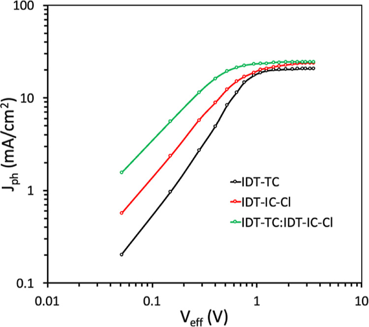
Jph–Veff plots for binary and ternary PSCs.
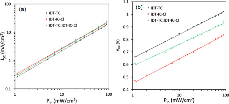
The degree of recombination is a key factor in determining the PCE of PSCs, in addition to exciton dissociation and charge collection. Therefore, as shown in Figure 9, we investigated JSC and VOC dependence on incident power intensity. The JSC varies with Pin as JSC ∝ (Pin)α, where α is the power exponent, which indicates the degree of bimolecular recombination. The bimolecular recombination is almost negligible when α is close to unity.71 We have estimated the value of α from the JSC-Pin plots (Figure 9a). P: IDT-IC-Cl showed a small value of 0.942 than P: IDT-TC (0.964), demonstrating a higher bimolecular recombination in the P: IDT-IC-Cl-based binary PSC. However, compared to binary P:IDT-IC-Cl and P:IDT-TC devices, the value of α was increased to 0.976 for the optimized ternary device, demonstrating that the introduction of IDT-TC into the binary P:IDT-IC-Cl effectively suppresses the bimolecular recombination, which is beneficial for attaining high values of both JSC and FF. The variation of VOC with Pin also gives information about another type of recombination, that is, trap-assisted recombination (Figure 9b). The variation of VOC with Pin (Figure 9b) can be expressed as VOC = (nkT/q)ln Pin, where n is the diode ideality factor, k is the Boltzmann’s constant, and T is the absolute temperature. The values of n are estimated to be 1.32, 1.25, and 1.15 for optimized P: IDT-IC-Cl, IDT-TC, and P:IDT-TC: IDT-IC-Cl, respectively. It is well known that when the value of n is close to 2, trap-assisted recombination predominates in PSCs under open-circuit circumstances. In contrast, bimolecular recombination predominates if the value of n is close to unity.72 As evidenced by the greatest values of JSC and FF, the lowest value of n for ternary PSCs suggests the least amount of trap-assisted recombination in ternary PSCs.73
Figure 9.
Variations of (a) JSC and (b) VOC with Pin for binary and ternary devices.
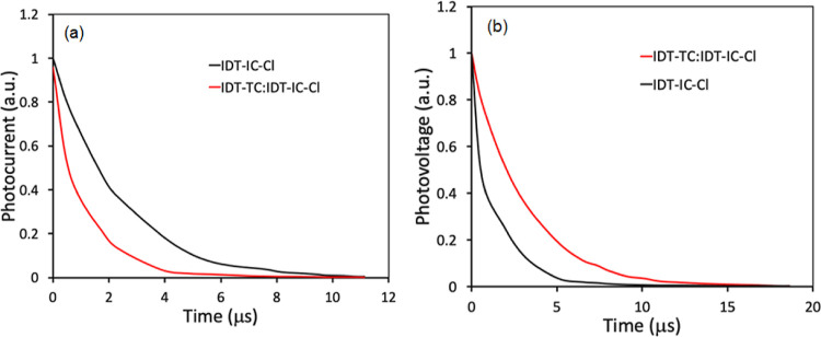
The charge carrier dynamics are also analyzed by transient photocurrent (TPC) and transient photovoltage (TPV) measurements. We have estimated the charge extraction time (τext) by fitting the TPC decays under short-circuit conditions74 (Figure 10a). The τext values for P: IDT-IC-Cl and the ternary P:IDT-TC: IDT-IC-Cl are fitted to be 3.67 and 2.39 μs, respectively. Small τext for the ternary device indicates promoted efficiency of charge sweep-out and demonstrates the faster charge extraction than the binary counterpart. Furthermore, TPC under open-circuit conditions is performed to get information about the charge carrier lifetime and reflect the recombination time of the photocharge carrier (τrec).75 The τrec values estimated from the TPC plots (Figure 10b) for the ternary device are about 8.34 μs, which is higher than that for the binary counterpart (6.45 μs), demonstrating the effective suppression of charge recombination in the ternary PSC. Therefore, these results again validate the superior charge extraction and suppressed charge recombination loss in the ternary PSC.
Figure 10.
(a) TPC and (b) TPV curves for binary and ternary devices.
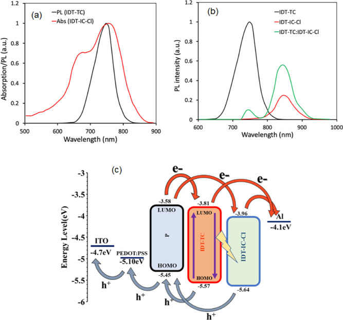
We have compared the absorption spectra of IDT-IC-Cl and steady-state photoluminescence (PL) spectra of IDT-TC to investigate the intermolecular dynamic process between these two acceptors. As presented in Figure 11a, most of the PL spectra of IDT-TC overlapped with the PL absorption spectra of IDT-IC-Cl, demonstrating effective energy transfer from IDT-TC to IDT-IC-Cl in line with Forster theory.76,77 In order to verify this energy transfer process, we have recorded the PL spectra of IDT-IC-Cl, IDT-TC, and their blend, which are presented in Figure 11b. The PL emission of IDT-TC was efficiently quenched in IDT-TC:IDT-IC-Cl, whereas the intensity of the PL emission peak located at 888 nm is significantly increased, revealing the efficient energy transfer between IDT-TC and IDT-IC-Cl78 as presented in Figure 11c.
Figure 11.
(a) Thin-film PL spectra of IDT-TC and absorption spectra of IDT-IC-Cl, (b) thin-film PL spectra of pristine IDT-TC, IDT-IC-Cl, and optimized IDT-TC:IDT-IC-Cl, and (c) working mechanism of the ternary PSC.
We constructed the devices using the pristine acceptors, and their optimum blend and J–V characteristics were examined to learn more about the potential for charge (electrons and holes) transfer between two acceptors. We found that the JSC values of the device based on the blend of acceptors lie between the pure acceptor devices, indicating that charge transfer between two acceptors does not occur. The possible energy transfer and charge transfer that occurred in the ternary device are presented in Figure 11c. The transfer of electrons from polymer donor P to IDT-TC or IDT-IC-Cl and holes from either IDT-TC or IDT-IC-Cl occur. Therefore, more D/A interfaces (P/IDT-TC and P/IDT-IC-Cl) are created in the active ternary layer, whereas only P/IDT-IC-Cl interfaces are present in the active binary layer. As the number of interfaces depends upon the morphology of the blended film and D/A ratio, the more creation of D/A interfaces owing to the nanoscale morphology of the ternary active layer is beneficial for enhanced exciton dissociation. In the ternary active layer-based PSC, the effective utilization of exciton occurs via energy transfer from IDT-TC to IDT-IC-Cl, thereby enhancing the exciton generation rate and leading to a high value of JSC.
3.7. TEM and XRD Results
An essential factor that affects the photovoltaic performance of PSCs, especially the JSC and FF, is the molecular crystallinity and morphology of the active layer. Therefore, we have examined the molecular crystallinity of the binary (P:IDT-IC-Cl) and ternary (P:IDT-TC:IDT-IC-Cl) films via recording the XRD patterns as displayed in Figure 12. Both binary and ternary films showed two diffraction peaks at 2θ = 5.63/6.09° (corresponds to lamellar stacking) and 2θ = 24.09/24.78° (corresponds to π–π stacking), respectively. The d-spacing and π–π stacking distances for binary and ternary films are 1.59/0.361 and 1.47/0.351 nm, respectively. The crystal coherence distances (CCLs) corresponding to lamellar stacking/π–π stacking for binary and ternary films are 5.22/6.47 and 3.48/3.53 nm, respectively. It is advantageous for effective charge transport, which lowers charge recombination and supports high values of JSC and FF, to have a greater value of CCL (owing to the higher crystallinity of IDT-TC) and a smaller value of π–π stacking distance for the ternary film.
Figure 12.
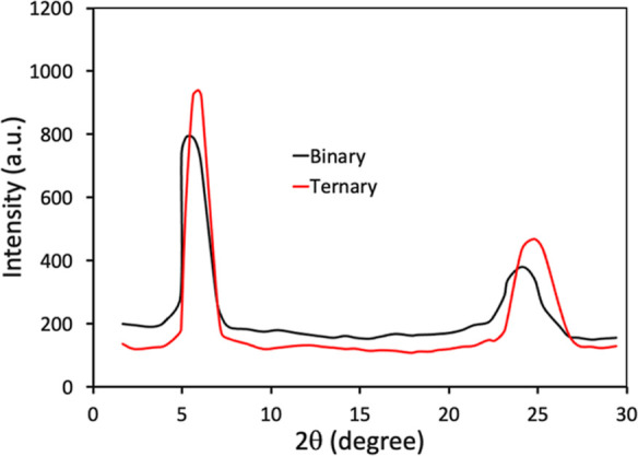
XRD patterns of binary (P:IDT-IC-Cl) and ternary (P:IDT-TC:IDT-IC-Cl) films.
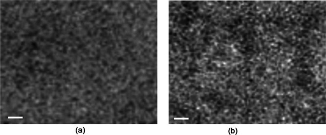
Figure 13 depicts the results of a morphological analysis performed using transmission electron microscopy (TEM) on the active layers. The active ternary films exhibit enhanced phase separation because the domain size in ternary films is larger than that in their binary counterparts. This improved phase separation can help facilitate exciton dissociation and suppress charge recombination via balanced charge transport, resulting in a greater value of FF.
Figure 13.
TEM images of optimized (a) P:IDT-IC-Cl and (b) P:IDT-TC:IDT-IC-Cl films. The scale bar is 100 nm.
4. Conclusions
In this work, we developed a novel medium bandgap non-fullerene SMA called IDT-TC, which is built on an IDT donor core and TC acceptor terminals. We compared its optical and electrochemical characteristics with those of IDT-IC. IDT-TC showed upshifted LUMO energy levels compared to IDT-IC. The PSCs based on P: IDT-TC demonstrated a PCE of 14.26% using a wide bandgap D–A conjugated polymer P, which is higher than that of the IDT-IC counterpart (11.56%). The greater values of FF and VOC for the IDT-TC-based device are responsible for the PCE, despite the fact that the JSC for the PSC based on IDT-IC is higher than that for IDT-TC. We have also fabricated the PSCs using a narrow bandgap NFA IDT-IC-Cl, and the P: IDT-IC-Cl-based device showed a PCE of 13.34%. We have included IDT-TC in P: IDT-IC-Cl as a guest acceptor to construct the ternary PSCs, taking advantage of greater values of JSC for the IDT-IC-Cl counterpart and higher values of VOC and FF for the binary BHJ PSCs based on IDT-TC. Following optimization, the ternary PSCs displayed a fantastic PCE of 16.44% (JSC = 23.98 mA/cm2, VOC = 0.98 V, and FF = 0.714). Faster charge extraction in the ternary PSCs, more balanced charge transport, less charge recombination, and the usage of excitons via energy transfer from IDT-TC to IDT-IC-Cl are all factors that contribute to PCE’s higher value. Additionally, the active ternary layer’s compact stacking distance and proper phase separation also contribute to the values of FF and JSC in the ternary PSCs.
Acknowledgments
This work was supported by the Ministry of Science and Higher Education of the Russian Federation (contract/agreement no. 075-00697-22-00) and was performed employing the equipment of the Center for molecular composition studies of INEOS RAS. G.D.S. is thankful to the Department of Science and Technology for providing the financial support through BRICS and Indo-Taiwan project.
Supporting Information Available
The Supporting Information is available free of charge at https://pubs.acs.org/doi/10.1021/acsomega.2c05141.
Instrumentation, synthesis of intermediate compounds, 1H NMR spectra and 13C NMR spectra of IDT-TC, TGA spectra, molecular geometries of IDT-TC, device fabrication method, dark J–V characteristics of the devices to estimate the charge carrier mobilities, XRD patterns of pristine films, PL spectra, and photovoltaic parameters of optimization of the performance of PSCs (PDF)
Author Contributions
All the authors have contributed equally and have given approval to the final version of the manuscript.
The authors declare no competing financial interest.
Supplementary Material
References
- Yu G.; Gao J.; Hummelen J. C.; Wudl F.; Heeger A. J. Polymer Photovoltaic Cells: Enhanced Efficiencies via a Network of Internal Donor-Acceptor Heterojunction. Science 1995, 270, 1789–1791. 10.1126/science.270.5243.1789. [DOI] [Google Scholar]
- Lee S.; Jeong D.; Kim C.; Lee C.; Kang H.; Woo H. Y.; Kim B. J. Eco-friendly polymer solar cells: Advance in Green Solvent Processing and Material Design. ACS Nano 2020, 14, 14493–14527. 10.1021/acsnano.0c07488. [DOI] [PubMed] [Google Scholar]
- Chen H.; Zhang R.; Chen X.; Zeng G.; Kobera L.; Abbrent S.; Zhang B.; Chen W.; Xu G.; Oh J.; Kang S.-H.; Chen S.; Yang C.; Brus J.; Hou J.; Gao F.; Li Y.; Li Y. A Guest-Assisted Molecular Organization Approach for >17 % Efficiency Organic Solar Cells Using Environmentally Friendly Solvents. Nat. Energy 2021, 6, 1045–1053. 10.1038/s41560-021-00923-5. [DOI] [Google Scholar]
- Lu L.; Zheng T.; Wu Q.; Schneider A. M.; Zhao D.; Yu L. Recent Advances in Bulk Heterojunction Polymer Solar Cells. Chem. Rev. 2015, 115, 12666–12731. 10.1021/acs.chemrev.5b00098. [DOI] [PubMed] [Google Scholar]
- Duan L.; Uddin A. Progress in Stability of Organic Solar Cells. Adv. Sci. 2020, 7, 1903259. 10.1002/advs.201903259. [DOI] [PMC free article] [PubMed] [Google Scholar]
- Chen L. X. Organic solar cells: Recent Progress and Challenges. ACS Energy Lett. 2019, 4, 2537–2539. 10.1021/acsenergylett.9b02071. [DOI] [Google Scholar]
- Hong L.; Yao H.; Cui Y.; Ge Z.; Hou J. Recent Advances in Highly Efficiency Organic Solar Cells Fabricated by Eco-compatible Solvents at Relatively Large Area Scale. APL Mater. 2020, 8, 120901. 10.1063/5.0027948. [DOI] [Google Scholar]
- Yang F.; Huang Y.; Li Y.; Li Y. Large-Area Flexible Organic Solar Cells. npj Flexible Electron. 2021, 5, 30. 10.1038/s41528-021-00128-6. [DOI] [Google Scholar]
- Yuan J.; Zhang Y.; Zhou L.; Zhang G.; Yip H.-L.; Lau T.-K.; Lu X.; Zhu C.; Peng H.; Johnson P. A.; Leclerc M.; Cao Y.; Ulanski J.; Li Y.; Zou Y. Single Junction Organic Solar Cell with Over 15 % Efficiency Using Fused Ring Acceptor with Electron-Deficient Core. Joule 2019, 3, 1140–1151. 10.1016/j.joule.2019.01.004. [DOI] [Google Scholar]
- Jiang K.; Wei Q.; Lai J. Y. L.; Peng Z.; Kim H. K.; Yuan J.; Ye L.; Ade H.; Zou Y.; Yan H. Alkyl Chain Tunning of Small Molecule Acceptors for Efficient Organic Solar Cells. Joule 2019, 3, 3020–3033. 10.1016/j.joule.2019.09.010. [DOI] [Google Scholar]
- Xu X.; Qi Y.; Luo X.; Xia X.; Lu X.; Yuan J.; Zhou Y.; Zou Y. Alkyl Side-Chain Engineering Enables High Performance As Cast Organic Solar Cells of Over 17 % Efficiency. Fundam. Res. 2022, 10.1016/j.fmre.2022.01.025. [DOI] [PMC free article] [PubMed] [Google Scholar]
- Bi P.; Zhang S.; Chen Z.; Xu Y.; Cui Y.; Zhang T.; Ren J.; Qin J.; Hong L.; Hao X.; Hou J. Reduced Non-radiative Charge Recombination Enables Organic Photovoltaic Cell Approaching 19 % Efficiency. Joule 2021, 5, 2408–2419. 10.1016/j.joule.2021.06.020. [DOI] [Google Scholar]
- Chong K.; Xu X.; Meng H.; Xue J.; Yu L.; Ma W.; Peng Q. Realizing 19.05 % Efficiency Polymer Solar Cells by Progressively Improving Charge Extraction and Suppressing Charge Recombination. Adv. Mater. 2022, 34, e2109516 10.1002/adma.202109516. [DOI] [PubMed] [Google Scholar]
- Bao S.; Yang H.; Fan H.; Zhang J.; Wei Z.; Cui Y.; Li Y. Volatilizable Solid additive Assisted Treatment Enables Organic Solar Cells with Efficiency Over 18.8 % and Fill Factor Exceeding 80. Adv. Mater. 2021, 33, e2105301 10.1002/adma.202105301. [DOI] [PubMed] [Google Scholar]
- Zhang M.; Zhu L.; Zhou G.; Hao T.; Qiu C.; Zhao Z.; Hu Q.; Larson B. W.; Zhu H.; Ma Z.; Tang Z.; Feng W.; Zhang Y.; Russell T. P.; Liu F. Single Layered Organic Photovoltaics With Double Cascading Charge Transport Pathways:18 % Efficiencies. Nat. Commun. 2021, 12, 309. 10.1038/s41467-020-20580-8. [DOI] [PMC free article] [PubMed] [Google Scholar]
- Zhang X.; Li C.; Xu J.; Wang R.; Song J.; Zhang H.; Li Y.; Jing G.; Li J.; Wu X.; Zhou Y.; Li X.; Zhang J.; Li C.; Zhang H.; Zhang Y.; Zhou Y.; Sun Y.; Zhang Y. High Fill Factor Solar Cells with Increased Dielectric Constant and Molecular Packing Density. Joule 2022, 6, 444–457. 10.1016/j.joule.2022.01.006. [DOI] [Google Scholar]
- Li X.; Luo S.; Sun H.; Sung H. H. Y.; Yu H.; Liu T.; Xiao Y.; Bai F.; Pan M.; Lu X.; Williams I. D.; Guo X.; Li Y.; Yan H. Medium Bandgap Nonfulluerene Acceptors Based on Benzothiophene Donor Moiety Enabling High Performance Indoor Organic Photovoltaics. Energy Environ. Sci. 2021, 14, 4555–4563. 10.1039/d1ee00687h. [DOI] [Google Scholar]
- Ahn J.; Oh S.; Lee H.; Lee S.; Song C. E.; Lee H. K.; Lee S. K.; So W. W.; Moon S. J.; Lim E.; Shin W. S.; Lee J. C. Simple and Versatile Nonfullerene Acceptor Based Benzothiadiazole and Rhodanine for Organic Solar Cells. ACS Appl. Mater. Interfaces 2019, 11, 30098–30107. 10.1021/acsami.9b09256. [DOI] [PubMed] [Google Scholar]
- Wang Y.; Chang M.; Ke X.; Wan X.; Yang G. A New Medium Bandgap Fused-[1]benzothieno[3,2-b]]1]benzo-thiophene (BTBT) Nonfullerene Acceptor for Organic Solar Cells with High Open Circuit Voltage. Polymer 2019, 185, 121976. 10.1016/j.polymer.2019.121976. [DOI] [Google Scholar]
- Cheng P.; Li G.; Zhan X.; Yang Y. Next Generation Organic Photovoltaics Based on Non-fullerene Acceptors. Nat. Photonics 2018, 12, 131–142. 10.1038/s41566-018-0104-9. [DOI] [Google Scholar]
- Li S.; Liu W.; Li C. Z.; Shi M.; Chen H. Efficient Organic Solar Cells with Non-fullerene Acceptors. Small 2017, 13, 1701120. 10.1002/smll.201701120. [DOI] [PubMed] [Google Scholar]
- Hou J.; Inganäs O.; Friend R. H.; Gao F. Orgnaic Solar Cells Based on Non-fullerene Ccceptors. Nat. Mater. 2018, 17, 119–128. 10.1038/nmat5063. [DOI] [PubMed] [Google Scholar]
- He B.; Yang B.; Kolaczkowski M. A.; Anderson C. A.; Klivansky L. M.; Chen T. L.; Brady M. A.; Liu Y. Molecular Engineering for Large Open Circuit Voltage and Low Energy Loss in Around 10 % Non-fullerene Organic Photovoltaics. ACS Energy Lett. 2018, 3, 1028–1035. 10.1021/acsenergylett.8b00366. [DOI] [Google Scholar]
- Zhang G.; Zhao J.; Chow P. C. Y.; Jiang K.; Zhang J.; Zhu Z.; Zhang J.; Huang F.; Yan H. Nonfullerene Acceptor Molecules for Bulk Heterojunction Organic Solar Cells. Chem. Rev. 2018, 118, 3447–3507. 10.1021/acs.chemrev.7b00535. [DOI] [PubMed] [Google Scholar]
- Fan Q.; Xu Z.; Guo X.; Meng X.; Li W.; Su W.; Ou X.; Ma W.; Zhang M.; Li Y. High-Performance Nonfullerene Polymer Solar Cells with Open-Circuit Voltage Over 1.0 V and Energy Loss as Low as 0.54 eV. Nano Energy 2017, 40, 20–26. 10.1016/j.nanoen.2017.07.047. [DOI] [Google Scholar]
- Cui Y.; Yao H.; Gao B.; Qin Y.; Zhang S.; Yang B.; He C.; Xu B.; Hou J. Fine Tuned Photoactive and Interconnection Layers for Achieving over 13 % Efficiency in a Fullerene Free Tandem Organic Solar Cell. J. Am. Chem. Soc. 2017, 139, 7302–7309. 10.1021/jacs.7b01493. [DOI] [PubMed] [Google Scholar]
- Liu G.; Jia J.; Zhang K.; Jia X.; Yin Q.; Zhong W.; Li L.; Huang F.; Cao Y. 15 % Efficiency Tandem Organic Solar Cells Based on a Novel Highly Efficient Wide Bandgap Nonfullerene Acceptor with Low Energy Loss. Adv. Energy Mater. 2019, 9, 1803657. 10.1002/aenm.201803657. [DOI] [Google Scholar]
- Meng L.; Yi Y.-Q.-Q.; Wan X.; Zhang Y.; Ke X.; Kan B.; Wang Y.; Xia R.; Yip H.-L.; Li C.; Chen Y. A Tandem Organic Solar Cell with PCE of 14.25 % Employing Subcells with the Same Polymer Donor and Two Absorption Complementary Acceptors. Adv. Mater. 2019, 31, 1804723. 10.1002/adma.201804723. [DOI] [PubMed] [Google Scholar]
- Cheng P.; Liu Y.; Chang S. Y.; Li T.; Sun P.; Wang R.; Cheng H. W.; Huang T.; Meng L.; Nuryyeva S.; Zhu C.; Wei K. H.; Sun B.; Zhan X.; Yang Y. Efficient Tandem Organic Photovoltaics with Tunable Rear Sub-cells. Joule 2019, 3, 432–442. 10.1016/j.joule.2018.11.011. [DOI] [Google Scholar]
- Zhang Y.; Kan B.; Sun Y.; Wang Y.; Xia R.; Ke X.; Yi Y. Q. Q.; Li C.; Yip H. L.; Wan X.; Cao Y.; Chen Y. Nonfullerene Tandem Organic Solar Cells with High Performance of 14 .11. Adv. Mater. 2018, 30, 1707508. 10.1002/adma.201707508. [DOI] [PubMed] [Google Scholar]
- Meng L.; Zhang Y.; Wan X.; Li C.; Zhang X.; Wang Y.; Ke X.; Xiao Z.; Ding L.; Xia R.; Yip H. L.; Cao Y.; Chen Y. Organic and Solution Processed Tandem Solar Cells with 17 .3 % Efficiency. Science 2018, 361, 1094–1098. 10.1126/science.aat2612. [DOI] [PubMed] [Google Scholar]
- Liu Q.; Jin K.; Li W.; Xiao Z.; Cheng M.; Yuan Y.; Shi S.; Jin Z.; Hao F.; Yang S.; Ding L. An Efficient Medium Bandgap Nonfullerene Acceptor for Organic Solar Cells. J. Mater. Chem. A 2020, 8, 8857–8861. 10.1039/d0ta02427a. [DOI] [Google Scholar]
- Liu G.; Xia R.; Huang Q.; Zhang K.; Hu Z.; Jia T.; Liu X.; Yip H. L.; Huang F. Tandem Organic Solar Cells with 18.7 % Efficiency Enabled by Suppressing the Charge Recombination in Front Sub-cell. Adv. Funct. Mater. 2021, 31, 2103283. [Google Scholar]
- Di Carlo Rasi D.; Janssen R. A. J. Advances in Solution-Processed Multijunction Organic Solar Cells. Adv. Mater. 2019, 31, 18064999. 10.1002/adma.201806499. [DOI] [PubMed] [Google Scholar]
- Zhang M.; Wang J.; Ma X.; Gao J.; Xu C.; Hu Z.; Niu L.; Zhang F. Review on Smart Strategies for Achieving Highly Efficient Ternary Polymer Solar Cells. APL Mater. 2020, 8, 090703. 10.1063/5.0022887. [DOI] [Google Scholar]
- Doumon N. Y.; Yang L.; Rosei F. Ternary Organic Solar Cells: A Review of the Role of the Third Element. Nano Energy 2022, 94, 106915. 10.1016/j.nanoen.2021.106915. [DOI] [Google Scholar]
- Zhang X.; Wang Q.; Shen W.; Han C.; Shao Y.; Belfiore L. A.; Tang J. Recent advances and prospects of D1:D2:A non-fullerene ternary polymer solar cells. J. Mater. Chem. C 2021, 9, 41–66. 10.1039/d0tc04407e. [DOI] [Google Scholar]
- Zhao C.; Wang J.; Zhao X.; Du Z.; Yang R.; Tang J. Recent advances, Challenges and Prospects in Ternary Organic Solar Cells. Nanoscale 2021, 13, 2181–2208. 10.1039/d0nr07788g. [DOI] [PubMed] [Google Scholar]
- Wang T.; Wang X.; Yang R.; Li C. Recent Advances in Ternary Organic Solar Cells Based on Förster Resonance Energy Transfer. Solar RRL 2021, 5, 2100496. 10.1002/solr.202100496. [DOI] [Google Scholar]
- Gasparini N.; Salleo N. A.; McCulloch I.; Baran D. The role of the third component in ternary organic solar cells. Nat. Rev. Mater. 2019, 4, 229–242. 10.1038/s41578-019-0093-4. [DOI] [Google Scholar]
- Cheng H. W.; Juan C. Y.; Mohapatra A.; Chen C. H.; Lin Y. C.; Chang B.; Cheng P.; Wang H. C.; Chu C. W.; Yang Y.; Wei K. H. High-Performance Organic Photovoltaics Incorporating an Active Layer with a Few Nanometer-Thick Third-Component Layer on a Binary Blend Layer. Nano Lett. 2021, 21, 2207–2215. 10.1021/acs.nanolett.0c05045. [DOI] [PubMed] [Google Scholar]
- Sharma G. D.; Agrawal A.; Pradhan R.; Keshtov M. L.; Singhal R.; Liu W.; Zhu X.; Mishra A. Fullerene-Free All-Small-Molecule Ternary Organic Solar Cells with Two Compatible Fullerene-Free Acceptors and a Coumarin Donor Enabling a Power Conversion Efficiency of 14.5. ACS Appl. Energy Mater. 2021, 4, 11537–11544. 10.1021/acsaem.1c02277. [DOI] [Google Scholar]
- Privado M.; Dahiya H.; de la Cruz P.; Keshtov M. L.; Langa F.; Sharma G. D. A Ternary Organic Solar Cell with 15.6 % Efficiency Containing a New DPP-Based Acceptor. J. Mater. Chem. C 2021, 9, 16272–16281. 10.1039/d1tc02241e. [DOI] [Google Scholar]
- Suman S. P.; Singh S. P. Impact of End Groups on the Performance of Non-fullerene Acceptors for Organic Solar Cell Applications. J. Mater. Chem. A 2019, 7, 22701–22729. 10.1039/c9ta08620j. [DOI] [Google Scholar]
- Liu S.; Zhao B.; Cong Z.; Cheng Q.; Wang W.; Pan H.; Liu J.; Wu H.; Gao C. Influence of the Terminal Groups on the of Small Molecule Acceptors- Based Polymer Solar Cell. Dyes Pigments 2020, 178, 108388. 10.1016/j.dyepig.2020.108388. [DOI] [Google Scholar]
- Qiu N.; Zhang H.; Wan X.; Li C.; Ke X.; Feng H.; Kan B.; Zhang H.; Zhang Q.; Lu Y.; Chen Y. A New Nonfullerene Electron Acceptor with a Ladder Type Backbone for High-Performance Organic Solar Cells. Adv. Mater. 2017, 29, 1604964. 10.1002/adma.201604964. [DOI] [PubMed] [Google Scholar]
- Zhang Q.; Adil M. A.; Wang Z.; Zhao G.; Wang T.; Jiang R.; Zhang Q.; Wang Q. Influence of the terminal group on optoelectronic properties of fused-ring nonfullerene acceptors with ethylhexyl side chain. Dyes Pigm. 2021, 194, 109635. 10.1016/j.dyepig.2021.109635. [DOI] [Google Scholar]
- Zhang Z.; Feng L.; Xu S.; Yuan J.; Zhang Z. G.; Peng H.; Li Y.; Zou Y. Achieving Over 10 % Efficiency in a New Ccceptor ITTC and Its Blends with Hexafluoriquinoxaline Based Polymers. J. Mater. Chem. A 2017, 5, 11286–11293. 10.1039/c7ta02486j. [DOI] [Google Scholar]
- Liao L.; Zheng P.; Cai Z.; Shen S.; Xu G.; Zhao H.; Xu Y. Construction of Simple and Low Cost Acceptors for Efficient Non-fullerene Orgnaic Solar Cells. Organ. Electron. 2021, 89, 106026. 10.1016/j.orgel.2020.106026. [DOI] [Google Scholar]
- Zhang Y.; Cai F.; Yuan J.; Wei Q.; Zhou L.; Qiu B.; Hu Y.; Li Y.; Peng H.; Zou Y. A New Non-fullerene Acceptor Based on the Combination of a Heptacyclic Benzothiazole Unit and a Thiophene Fused End Group Cchieving Over 13 % Efficiency. Phys. Chem. Chem. Phys. 2019, 21, 26557. 10.1039/c9cp05015a. [DOI] [PubMed] [Google Scholar]
- Xie D.; Liu T.; Gao W.; Zhong C.; Huo L.; Luo Z.; Wu K.; Xiong W.; Liu F.; Sun Y.; Yang C. A Novel Thiophene Fused Ending Group Enabling an Excellent Small Molecule Acceptor for High-Performance Fullerene Free Polymer Solar Cells With 11.8 % Efficiency. Solar RRL 2017, 1, 1700044. 10.1002/solr.201700044. [DOI] [Google Scholar]
- Wu H.; Bian Q.; Zhao B.; Zhao L.; Wang W.; Wang Z.; Cong J.; Liu W.; Ma C.; Gao C. Effects of the Isomerized Thiophene Fused Ending Groups on the Performance of Twisted Non-fullerene Acceptor-Based Polymer Solar Cells. ACS Appl. Mater. Interfaces 2020, 12, 23904–23913. 10.1021/acsami.0c03842. [DOI] [PubMed] [Google Scholar]
- Keshtov M. L.; Kuklin S. A.; Dou C.; Koukaras E. N.; Singhal R.; Malhotra P.; Sharma G. D. Enhancement of Photovoltaic Efficiency Through Fine Adjustment of Indacene-based Non-fullerene Ccceptor by Minimal Chlorination for Polymer Solar Cells. Nano Select 2020, 1, 320–333. 10.1002/nano.202000027. [DOI] [Google Scholar]
- Keshtov M. L.; Kuklin S. A.; Khokhlov A. R.; Xie Z.; Alekseev V. G.; Dahiya H.; Singhal R.; Sharma G. D. New Medium Bandgap Donor D-A1-D-A2 Type Copolymers Based on Anthra[1,2-b: 4,3-b“:6,7-c”’] Trithiophene-8,12-dione Groups for High-Efficient Non-Fullerene Polymer Solar Cells. Macro. Rap. Commun. 2022, 43, 2100839. 10.1002/marc.202100839. [DOI] [PubMed] [Google Scholar]
- Hou J.; Huo L.; He C.; Yang C.; Li Y. Synthesis and Absorption Spectra of Poly(3-(phenylenevinyl)thiophene)s with Conjugated Side Chains. Macromolecules 2006, 39, 594–603. 10.1021/ma051883n. [DOI] [Google Scholar]
- Yao H.; Ye L.; Hou J.; Jang B.; Han G.; Cui Y.; Su G. M.; Wang C.; Gao B.; Yu R.; Zhang H.; Yi T.; Woo H. Y.; Ade H.; Hou J. Achieving Highly Efficient Nonfullerene Organic Solar Cells with Improved Intermolecular Interaction and Open Circuit Voltage. Adv. Mater. 2017, 29, 1700254. 10.1002/adma.201700254. [DOI] [PubMed] [Google Scholar]
- Huang J.; Tang H.; Yan C.; Li G. 1,1-dicyanomethylene-3-indanone End Group Engineering for Fused Electron Acceptor Based High-Performance Organic Photovoltaics. Cell Rep. Phys. Sci. 2021, 2, 100292. 10.1016/j.xcrp.2020.100292. [DOI] [Google Scholar]
- Chen S.; Wang Y.; Zhang L.; Zhao J.; Chen Y.; Zhu D.; Yao H.; Zhang G.; Ma W.; Friend R. H.; Chow P. C. Y.; Gao F.; Yan H. Efficient Nonfullerene Organic Solar Cells with Small Driving Force for Both Hole and Electron Transfer. Adv. Mater. 2018, 30, 1804215. 10.1002/adma.201804215. [DOI] [PubMed] [Google Scholar]
- Li S.; Zhan L.; Sun C.; Zhu H.; Zhou G.; Yang W.; Shi M.; Li C. Z.; Hou J.; Li Y.; Chen H. Highly Efficient Fullerene Free Organic Solar Cells Operated at Near Zero Highest Occupied Molecular Orbitals. J. Am. Chem. Soc. 2019, 141, 3073–3082. 10.1021/jacs.8b12126. [DOI] [PubMed] [Google Scholar]
- Doumon N. Y.; Yang L.; Rosei F. Ternary Organic Solar Cells: A Review of the Role of the Third Element. Nano Energy 2022, 94, 106915. 10.1016/j.nanoen.2021.106915. [DOI] [Google Scholar]
- Zhang S.; Ma X.; Xu C.; Xu W.; Xu W.; Jeong S. Y.; Woo H. Y.; Zhou Z.; Zhang X.; Zhang F.; Zhang F. Boosted Efficiency Over 18.1 % of Polymer Solar cells by Employing Large Extinction Coefficients Material as the Third Component. Macro. Rap. Commun. 2022, 43, 2200345. 10.1002/marc.202200345. [DOI] [PubMed] [Google Scholar]
- Ma X.; Zeng A.; Gao J.; Hu Z.; Xu C.; Son J. H.; Jeong S. Y.; Zhang C.; Li M.; Wang K.; Yan H.; Ma Z.; Wang Y.; Woo H. Y.; Zhang F. Approaching 18 % Efficiency of Ternary Organic Photovoltaics with Wide Bandgap Polymer Donor and Well Compatible Y6:Y6-10 as Acceptor. Nat. Sci. Rev. 2021, 8, nwaa305. 10.1093/nsr/nwaa305. [DOI] [PMC free article] [PubMed] [Google Scholar]
- An Q.; Wang J.; Gao W.; Ma X.; Hu Z.; Gao J.; Xu C.; Hao M.; Zhang X.; Yang C.; Zhang F. Alloy-Like Ternayr Polymer Solar Cells with Over 17.2 % Efficiency. Sci. Bull. 2020, 65, 538–545. 10.1016/j.scib.2020.01.012. [DOI] [PubMed] [Google Scholar]
- Sun C.; Qin S.; Wang R.; Chen S.; Pan F.; Qiu B.; Shang Z.; Meng L.; Zhang C.; Xiao M.; Yang C.; Li Y. High-Efficiency Polymer Solar Cells with Efficient Hole Transfer at Zero Highest Occupied Molecular Orbital Offset Between Methylated Polymer Donor and Brominated Acceptor. J. Am. Chem. Soc. 2020, 142, 1465–1474. 10.1021/jacs.9b09939. [DOI] [PubMed] [Google Scholar]
- Jiang H.; Han C.; Li Y.; Bi F.; Zheng N.; Han J.; Shen W.; Wen S.; Yang C.; Yang R.; Bao X. Rational Mutual Interactions in Ternary Systems Enable High-Performance Organic Solar Cells. Adv. Funct. Mater. 2020, 31, 2007088. 10.1002/adfm.202007088. [DOI] [Google Scholar]
- Xu W.; Li X.; Jeong S. Y.; Son J. H.; Zhou Z.; Jiang Q.; Woo H. Y.; Wu Q.; Zhu X.; Ma X.; Zhang F. Achieving 17.5 % Efficiency for Polymer Solar Cells via Donor and Acceptor Layerd Optimization. J. Mater. Chem. C 2022, 10, 5489–5496. 10.1039/d2tc00024e. [DOI] [Google Scholar]
- Khlyabich P. P.; Sezen-Edmonds M.; Howard J. B.; Thompson B. C.; Loo Y. L. Formaion of Organic Alloys in Ternary-Blend Solar Cells with Two Ccceptors Having Energy Level Offsets Exceeding 0.4 eV. ACS Energy Lett. 2017, 2, 2149–2156. 10.1021/acsenergylett.7b00620. [DOI] [Google Scholar]
- Röhr J. A.; Moia D.; Haque S. A.; Kirchartz T.; Nelson J. Exploring the Validity and Limitations of the Mott-Gurney Law for Charge Carrier Mobility Determination of Semiconducting Thin Films. J. Phys. Condens. Matter. 2018, 30, 105901. 10.1088/1361-648X/aaabad. [DOI] [PubMed] [Google Scholar]
- Song X.; Gasparini N.; Nahid M. M.; Chen H.; Macphee S. M.; Zhang W.; Norman V.; Zhu C.; Bryant D.; Ade H.; McCulloch I.; Baran D. A Highly Crystalline Fused Ring n-type Small Molecule for Nonfullerene Acceptor Based Organic Solar Cells and Field-Effect Transistors. Adv. Funct. Mater. 2018, 28, 1802895. 10.1002/adfm.201802895. [DOI] [Google Scholar]
- Shrotriya V.; Yao Y.; Li G.; Yang Y. Effect of Self-Organization in Polymer/Fullerene Bulk Heterojunctions on Solar Cell Performance. Appl. Phys. Lett. 2006, 89, 063505. 10.1063/1.2335377. [DOI] [Google Scholar]
- Blom P. W. M.; Mihailetchi V. D.; Koster L. J. A.; Markov D. E. Device Physics of Polymer: Fullerene Bulk Heterojunction Solar Cells. Adv. Mater. 2007, 19, 1551–1566. 10.1002/adma.200601093. [DOI] [Google Scholar]
- Chen Y.; Liu T.; Hu H.; Ma T.; Lai J. Y. L.; Zhang J.; Ade H.; Yan H. Modulation of End Groups for Low Bandgap Nonfullerene Acceptors Enabling High Performance Organic Solar Cells. Adv. Energy Mater. 2018, 8, 1801203. 10.1002/aenm.201801203. [DOI] [Google Scholar]
- Ma X.; Gao W.; Yu J.; An Q.; Zhang M.; Hu Z.; Wang J.; Tang W.; Yang C.; Zhang F. Ternary Nonfullerene Polymer Solar Cells With Efficiency > 13.7 by Integrating the Advantages of the Materials and Two Binary Cells. Energy Environ. Sci. 2018, 11, 2134–2141. 10.1039/c8ee01107a. [DOI] [Google Scholar]
- Yang L.; Song X.; Yu J.; Wang H.; Zhang Z.; Geng R.; Cao J.; Baran D.; Tang W. Tuning of the Conformation of Asymmetric Nonfullerene Acceptors for Efficient Organic Solar Cells. J. Mater. Chem. A 2019, 7, 22279–22286. 10.1039/c9ta07634d. [DOI] [Google Scholar]
- Song J.; Li C.; Zhu L.; Guo J.; Xu J.; Zhang X.; Weng K.; Zhang K.; Min J.; Hao X.; Zhang Y.; Liu F.; Sun Y. Ternary Organic Solar Cells with Efficiency > 16.5 Based on Two Compatible Nonfullerene Acceptors. Adv. Mater. 2019, 31, 1905645. 10.1002/adma.201905645. [DOI] [PubMed] [Google Scholar]
- MacKenzie R. C. I.; Shuttle C. G.; Chabinyc M. L.; Nelson J. Extracting Microscopic Device Parameters from Transient Photocurrent Measurements for P3HT:PCBM Solar Cells. Adv. Energy Mater. 2012, 2, 662. 10.1002/aenm.201100709. [DOI] [Google Scholar]
- Huang J. S.; Goh T.; Li X.; Sfeir M. Y.; Bielinski E. A.; Tomasulo S.; Lee M. L.; Hazari N.; Taylor A. D. Polymer Bulk Heterojunction Solar Cells Employing Forster Resonance Energy Transfer. Nat. Photonics 2013, 7, 479–485. 10.1038/nphoton.2013.82. [DOI] [Google Scholar]
- Lv R.; Chen D.; Liao X.; Chen L.; Chen Y. A Terminally Tetrafluorinated Nonfullerene Acceptor for Well Performing Ally Ternary Solar Cells. Adv. Funct. Mater. 2019, 29, 1805872. 10.1002/adfm.201805872. [DOI] [Google Scholar]
Associated Data
This section collects any data citations, data availability statements, or supplementary materials included in this article.


