Abstract
Fast volumetric imaging of large fluorescent samples with high-resolution is required for many biological applications. Oblique plane microscopy (OPM) provides high spatiotemporal resolution, but the field of view is typically limited by its optical train and the pixel number of the camera. Mechanically scanning the sample or decreasing the overall magnification of the imaging system can partially address this challenge, albeit by reducing the volumetric imaging speed or spatial resolution, respectively. Here, we introduce a novel dual-axis scan unit for OPM that facilitates rapid and high-resolution volumetric imaging throughout a volume of 800 × 500 × 200 microns. This enables us to perform volumetric imaging of cell monolayers, spheroids and zebrafish embryos with subcellular resolution. Furthermore, we combined this microscope with a multi-perspective projection imaging technique that increases the volumetric interrogation rate to more than 10 Hz. This allows us to rapidly probe a large field of view in a dimensionality reduced format, identify features of interest, and volumetrically image these regions with high spatiotemporal resolution.
1. Introduction
Recent developments in Oblique Plane Microscopy (OPM) [1–4] have demonstrated its potential for 5D (XYZλT) live imaging of cells and small model organisms. As a form of Light-Sheet Fluorescence Microscopy (LSFM), OPM leverages a highly parallelized acquisition scheme, which greatly reduces photobleaching [5]. Moreover, it uses a single objective for both illumination and detection, which alleviates the imaging space constraint inherent to most LSFMs, reduces the complexity of sample preparation, and brings great potential for high throughput volumetric imaging [6]. Lastly, rapid volumetric imaging can be achieved in OPM systems using rotating polygon mirrors [2] or galvanometric mirrors [7,8] that scan the light-sheet and de-scan the fluorescence light.
OPM can perform subcellular imaging [3,4], albeit with a restricted field-of-view (FOV) owing to the many optical components in the detection train. The FOV of OPM systems has been increased by mechanically scanning the stage [9] or decreasing the overall magnification of the imaging system towards mesoscopic imaging [10,11]. However, these approaches lead to either reduced volumetric imaging speed or lower spatial resolution.
Some constraints on the FOV in OPM, particularly in the realm of high-resolution imaging, result from the employed remote focusing mechanism [12]. Proper remote focusing is necessary to create a distortion free image of the oblique light-sheet plane, which in turn is picked up by an appropriately tilted tertiary imaging system [1]. To work properly, the magnification from sample space to remote image space needs to be equal to the ratio of the refractive indices between these two spaces [12]. Typically, a magnification of 1.33-1.51 is required, depending on the choice of the immersion media used. Due to the fixed magnification requirement for remote focusing, the tertiary imaging system must perform the bulk of the magnification (e.g., ∼50X for high resolution OPM [3]) to satisfy the Nyquist criterion for spatial sampling. In addition, its FOV gets further demagnified from the remote space to the sample space. Therefore, the tertiary imaging system forms a bottleneck for imaging large samples, whereas in principle lower magnification objectives supporting large FOVs can be used for the remote focusing system.
Here we overcome the FOV challenges by developing an all-optical tiling approach. By scanning the light-sheet in two-dimensions, a large portion of the FOV of the primary objective can be accessed, and the returning fluorescence light is de-scanned and passed through the narrower FOV of the tertiary imaging system. As such, we can extend the FOV in OPM more than 2.5-fold, while avoiding any time-consuming mechanical scanning of the sample and without sacrificing spatial resolution and Nyquist sampling. We carefully characterize the optical performance over the extended field of view, and perform dynamic imaging of single cells, cell monolayers, spheroids, zebrafish vasculature development, the flow of blood cells through the zebrafish heart and interactions of immune and cancer cells.
2. Methods
2.1. Optical tiling in OPM
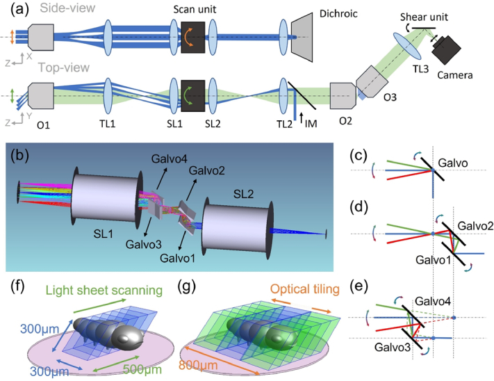
For optical tiling OPM, a two-dimensional light-sheet scanning approach is employed to extend the field of view: the light-sheet is scanned in one direction to obtain a 3D stack [see also “top view” in Fig. 1(a) and Fig. 1(f)] as in conventional OPM. The other scan dimension is used to extend the field of view by optical tiling [see also “side view” in Fig. 1(a) and Fig. 1(g)], here by acquiring three stacks with different lateral displacements. With this approach we achieve a scan range of 500 µm for a single 3D Stack and extend the lateral width ∼2.5 fold from ∼300 µm with no tiling [Fig. 1(f), limited by the diffraction limited FOV of the tertiary objective O3] to 800 µm with optical tiling [Fig. 1(g)]. The tiles have a 60.5 microns wide overlap region (∼20% width of a single tile), which was sufficient for computational image fusion of the samples shown in this manuscript.
Fig. 1.
(a) Schematic drawing of the OPM system with optical tiling. O1-3, objectives; TL1-3, Tube Lenses; SL1-2, Scan Lenses, IM, Illumination Module. (b) Rendering of the optical layout of the dual-axis scan unit and scan lenses. (c)-(e) Working principle of a single-galvo, dual-galvo and quad-galvo scan unit. (f) Image volume covered by conventional OPM (blue volume). (g) Image volume covered by optical tiling OPM (blue and green volumes). The pink circle depicts the field of view of the primary objective.
A pixel size of 150 nm assures Nyquist sampling for an optical resolution around 400 nm. The maximum height of the imaging volume (z-direction) is 200 µm, which is limited both by the length of the light-sheet and the size of the camera. Importantly, tiling occurs in the lateral direction, and should not be confused with Tiling light-sheet microscopy [13], which scans the light-sheet axially (i.e. along the propagation direction of the light-sheet).
2.2. Dual-axis scan unit
To enable telecentric 2D scanning in sample space, typically two galvo mirrors need to be located conjugate to the pupil plane of the primary objective, which requires a relay lens pair between the two orthogonal galvos. This increases the complexity and reduces the light-efficiency of the whole imaging system. To address this challenge, we designed a compact optical dual-axis scan unit, which is based on the original idea that two mirrors can steer a beam through an arbitrary point in space at different angles. Specifically, our scan unit consists of two galvo pairs with 15 mm distance between each galvo (GVS211, Thorlabs), as shown in Fig. 1(b). Pair 1, which includes Galvo 1 and 2, is placed orthogonal to Pair 2 (Galvo 3 and Galvo 4). When the scanning angle of Galvo 2 is twice the scanning angle of Galvo 1, the laser beam will pass through a common point [Fig. 1(d)]. When this point lies in the focal plane of the scan lens, the resulting scanning is analogous to a single galvo conjugated to the pupil plane of the primary objective [Fig. 1(c)]. For Pair 2, when the scanning angle of Galvo 3 is set to twice the scanning angle of Galvo 4, a virtual scan point [Fig. 1(e)] is formed that also acts in the same way as a properly conjugated single galvo mirror. By placing the common point of Pair 1 and the virtual point of Pair 2 at the focal plane of a scan lens, we can realize dual-axis telecentric scanning without requiring additional lenses. Importantly, the dual-axis scan unit was designed to fit in the same space where in a conventional OPM a single galvanometric mirror is located while using commercial scan lenses. As such, the unit can be retrofitted into existing OPM systems without the need of exchanging or adding new scan or relay lenses. A detailed analysis of dual-axis scanning can be found in Section 1 and an alignment guide in Section 2, both in Supplement 1 (3.7MB, pdf) .
2.3. Experimental setup
A schematic of our OPM with the dual-axis scan unit is shown in Fig. 1(a). A remote focusing system contains the primary objective O1 (NA 1.1, 25X, Nikon, MRD77220), tube lens TL1 (TTL200, Thorlabs), tube lens TL2 (169 mm Lens assembly [14], TTL200MP and AC508-750-A, Thorlabs) and the secondary objective O2 (20X NA 0.8, air, Olympus, UPLXAPO20X). Two scan lenses, SL1 and SL2 (CLS-SL, Thorlabs), and the dual-axis scan unit [see also Fig. 1(b)] are inserted between TL1 and TL2 to scan the light-sheet and de-scan the fluorescence light. The excitation laser [blue in Fig. 1(a)] from the illumination module (IM) was introduced into the system by a dichroic mirror (Di03-R405/488/561/635-t1-25 × 36, Semrock) between TL2 and O2. IM consists of a fiber coupled laser module, a Powell lens to generate a uniformly illuminated line and an electrically tunable lens to optionally enable axially swept light-sheet microscopy (ASLM [15], detailed in Section 3 and 4 of Supplement 1 (3.7MB, pdf) . This mode was not used for the data shown in the main manuscript). The remote focus image formed via O2 by fluorescence light [green in Fig. 1(a)] is collected by the tertiary imaging system, which is tilted by the same angle (45 degrees) as the light-sheet in the sample plane. The tertiary imaging system consists of a solid immersion objective O3 (AMS-AGY v2, Applied Scientific Instrumentation), a tube lens TL3 (AC508-300-A-ML, Thorlabs) and a scientific camera (ORCA-Flash, C13440-20CU, Hamamatsu). This configuration leads to an OPM system with an estimated NA of ∼1 (see also Section 5 of Supplement 1 (3.7MB, pdf) ). The overall magnification of the imaging system is 43.4, corresponding to a pixel size of ∼150 nm. To enable optical de-skewing and multi-perspective projection imaging, we also placed a galvanometer-based shear unit in front of the camera [16] (see also Section 6 of Supplement 1 (3.7MB, pdf) ).
3. Results
3.1. Resolution characterization
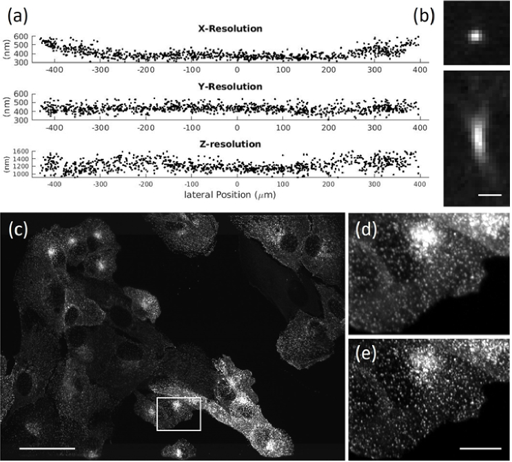
To characterize the resolving power of our optical tiling OPM system, we measured the full width half maximum (FWHM) of 100 nm diameter fluorescent nanospheres and performed image decorrelation analysis on subcellular features (Fig. 2). The average resolution across the extended FOV was 0.39 ± 0.05, 0.43 ± 0.04 and 1.22 ± 0.13 µm (n = 943) in the x, y, and z direction, respectively, as measured by the FWHM [see also Fig. 2(a)]. While the y and z resolution remained relatively constant, the x resolution deteriorated at the periphery of the FOV. This was expected due to some light clipping by the galvo scan unit (see also Fig. S5 in Section 1 of Supplement 1 (3.7MB, pdf) .) Importantly, the z-resolution is better than in a recently published OPM system designed for mechanical tiling with similar optical specifications [9]. This is mainly driven by the detection PSF (i.e., measured using widefield illumination and OPM detection), which featured an axial FWHM of 1.10 ± 0.15 µm (n = 244). As such we achieve an axial resolution of around one micron while using large light-sheets, which are required to image multi-cellular specimens.
Fig. 2.
(a) Full Width Half Maximum measurements of fluorescent nanospheres over the whole FOV. (b) Representative point-spread function of a fluorescent nanosphere. (c) Maximum intensity projection of parental human retinal pigmented epithelium (ARPE-19) cells EGFP-labeled for AP2. (d) Raw data for box in (c). (e) Deconvolved data for box in (c). Scale bars: (b)1 µm; (c) 50 µm; (e) 10 µm.
To evaluate the resolving power in a cellular context, we imaged clathrin coated pits. Figure 2(c) shows a group of ARPE cells labeled with EGFP for AP2 [17], as imaged with our OPM system, while the insets in Fig. 2(d-e) show magnified regions before and after deconvolution. Using image decorrelation analysis on the whole image, we could verify that in a cellular context we achieve 408 nm resolution in the raw data, and 294 nm resolution after deconvolution (Data was resampled onto a finer grid prior to deconvolution. See also Fig. S16 in Section 7 of Supplement 1 (3.7MB, pdf) ).
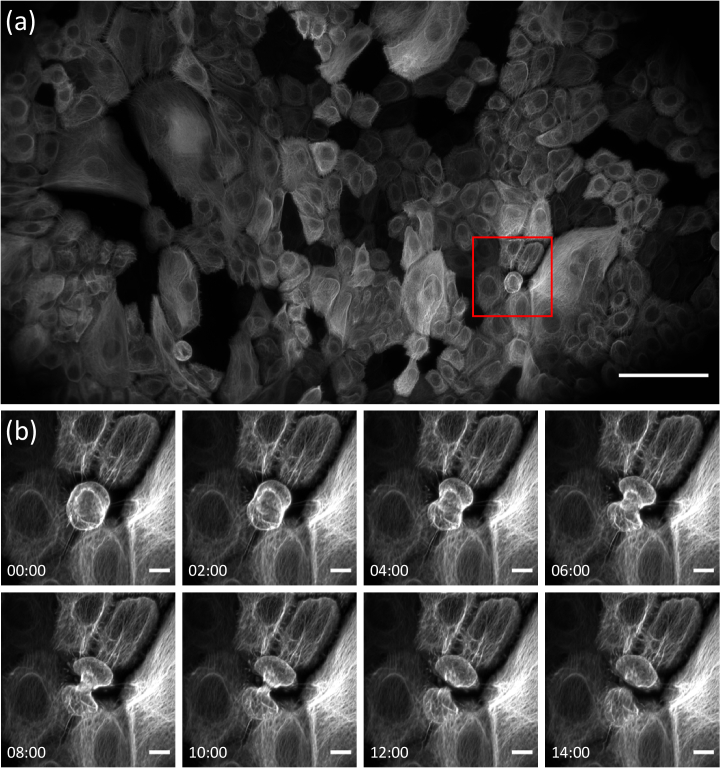
To demonstrate the ability of the system to capture high-resolution time-lapse images across the extended field of view we performed longitudinal imaging (time interval of 30 sec) of cultured keratinocytes stably expressing a fluorescently tagged intermediate filament protein [keratin 5 (K5)-mNeonGreen]. We were able to capture finely detailed images of subcellular movement of the keratin intermediate filament cytoskeleton simultaneously across many cells in a monolayer (Fig. 3). We can also see multiple cell divisions through such a large FOV (Fig. 3(b) and Supplementary Visualization 1 (12.2MB, mp4) ). The image was fused from three optically tiled volumes, each consisting of 2048 × 200 × 1001 pixels corresponding to a data size of 783 MB. After shearing and rotation of the raw data, cropping of void areas and fusion of the three tiles, the extended volume measures 5354 × 3479 × 147 pixels, which corresponds to a volume spanning ∼800 × 500 × 22 µm3.
Fig. 3.
Imaging of the intermediate filament cytoskeleton in a monolayer of cultured keratinocytes expressing keratin 5 (K5)-mNeonGreen. (a) Maximum intensity projection of the tiled volume. A gamma correction of 0.7 has been applied. (b) Zoom on the red boxed region in (a), demonstrating profound rearrangement of the intermediate filament network during cell division. Scale bars: (a) 100 µm, (b) 10 µm. Timestamp: mm: ss.
A resolution analysis across the extended field of view is presented in Fig. S17 in section 7 of Supplement 1 (3.7MB, pdf) . The preparation of the keratinocyte sample is detailed in Section 8 and a guide to image stitching is provided in Section 9, both in Supplement 1 (3.7MB, pdf) .
3.2. Cellular and organoid imaging
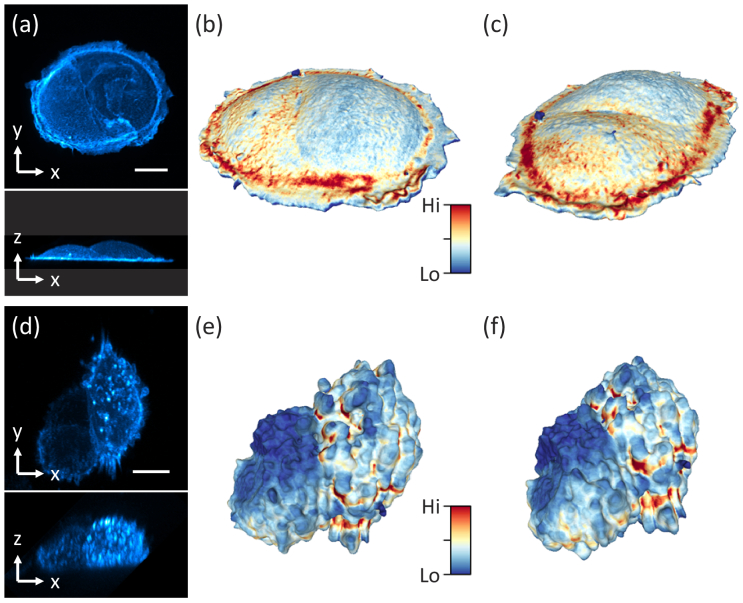
To demonstrate the spatiotemporal resolution of the system, we volumetrically imaged single cells and multicellular constructs at 5 and 7.5 sec time intervals, respectively. Figure 4(a) shows maximum intensity projections (MIP) of a SU8686 pancreatic ductal adenocarcinoma cell (acquired from ATCC, CRL-1837) labeled with Tractin-CyOFP1, and after deconvolving the OPM data. Importantly, the cross-sectional view revealed excellent optical sectioning and enough resolving power to distinguish surface ruffles. In Fig. 4(b-c), renderings of the segmented SU8686 cell from two viewpoints are shown, with the color indicating surface intensity. Figure 4(d) shows MIPs of a spheroid made of colorectal adenocarcinoma cancer cells DLD1 labeled with tractin-GFP after deconvolving the OPM data (cell culture description in Section 10 of Supplement 1 (3.7MB, pdf) ). Figure 4(e-f) shows renderings of the segmented surface from two viewpoints, with the color indicating surface intensity. The 3D segmentation and surface rendering are discussed in detail in Section 11 of Supplement 1 (3.7MB, pdf) . Time-lapse imaging of the spheroid is shown in Supplementary Visualization 2 (9.2MB, mp4) , which reveals rapid protrusion dynamics that are resolved spatially and temporally.
Fig. 4.
Imaging of single cells and spheroids. (a) Maximum intensity projection (MIP) of a SU8686 cell in xy and xz. (b-c) 3D rendering of the cell surface from two different views. Color encodes surface intensity. (d) MIPs of a Colon cancer cell spheroid in xy and xz. (e-f) 3D rendering of the surface from two different views. Scale bars: (a) 20 µm, (d) 10 µm.
3.3. Intravital imaging
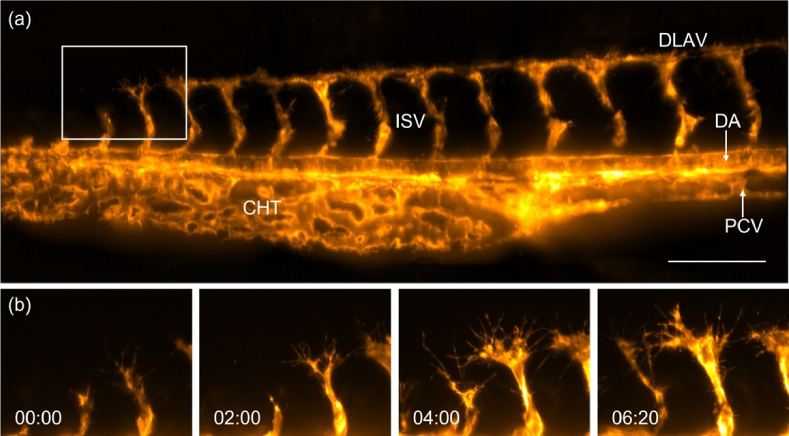
To demonstrate the potential of optical tiling OPM for high-resolution intravital microscopy, we performed longitudinal imaging of the vascular development in the zebrafish tail. For this, a 1.5 days old zebrafish labeled with the vasculature marker Tg(kdrl:Hsa.HRAS-mCherry) [18] was imaged every 10 minutes over a time span of 16 hours (the design of a water reservoir for long-term imaging is discussed in Section 12 of Supplement 1 (3.7MB, pdf) ). To visualize the majority of the tail vasculature at each timepoint, three optically tiled stacks were acquired and computationally fused together using BigStitcher [19] [ Fig. 5(a), Supplementary Visualization 3 (9.7MB, mp4) ]. The high resolving power of our system enabled us to visualize the intricate process of tip cell migration of the nascent intersegmental vessel (ISV), the active extension of numerous endothelial filopodia that dynamically probe the environment, and initiation of anastomosis (vessel fusion) between neighboring sprouts, resulting in a new vessel, the dorsal longitudinal anastomotic vessel (DLAV) [Insets in Fig. 5(b)].
Fig. 5.
Imaging of zebrafish vasculature with optical tiling OPM. (a) Tail of a 1-2 d old Zebrafish labeled with Tg(kdrl:Hsa.HRAS-mCherry), as imaged by optical tiling OPM. A maximum intensity projection of three volumes that have been computationally stitched together is shown. DLAV, Dorsal longitudinal anastomotic vessel; DA, Dorsal aorta; PCV, Posterior cardinal vein; ISV, Intersegmental blood vessel; CHT, caudal hematopoietic tissue. (b) Enlarged views of the boxed region in (a) show the development of intersegmental vessels in the zebrafish tail. Scale bar: 100 µm. Timestamp: hh:mm.
3.4. Projective and hybrid imaging modality
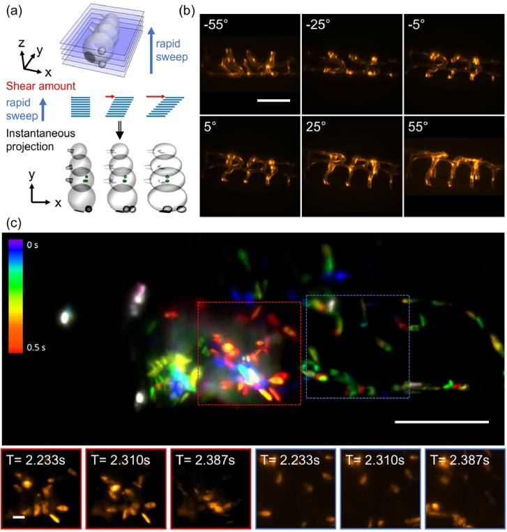
We further demonstrate that our optical tiling technique can be used to extend the FOV in applications that require acquisition speeds that lie outside the timescales accessible with conventional 3D stacking. One promising approach to do so is the recently introduced real-time multi-angle projection method [16]. Figure 6(a) shows the schematic principle of the projection mechanism: The light-sheet is rapidly swept through the sample (completing at least one sweep per camera exposure). Synchronized to this sweep, the shear galvo is translating the instantaneous images across the image sensor. This results in an optical implementation of the shear-warp transform, yielding projections of the sample under variable viewing angles [Fig. 6(a), bottom]. As an example, six different projections of vasculature in the zebrafish tail, labeled with the vascular marker Tg(kdrl:EGFP) [20], are shown in Fig. 6(b). By rapidly tiling three projections, we imaged the beating heart of a zebrafish, labeled with the vascular marker Tg(kdrl:EGFP) and the red blood cell marker Tg(gata1a:dsRed) [21] in a casper background [22]. We achieved an overall acquisition rate of 13 Hz using 3 optical tiles, projected over a depth of 100 microns [Fig. 6(c), with time coded by color, and supplementary Visualization 4 (6.3MB, mp4) ].
Fig. 6.
Extending the field of view in real time projection imaging. (a) Schematic representation of the projection method: the light-sheet is rapidly swept through the sample, and the instantaneous images are translated at the same rate on the camera sensor. Depending on the amount of lateral translation, projections under different viewing angle are obtained. (b) Projections of vasculature in the zebrafish tail under different viewing angles. (c) Tiled projection imaging of fluorescently labeled blood cells in a zebrafish heart. Insets show a montage of blood cells at different timepoints. Scale bars: (b-c) 100 µm and insets 10 µm.
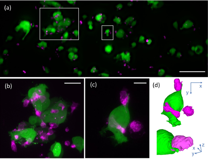
Lastly, we show that a combination of projection and 3D imaging can be used to follow the dynamics of human natural killer cells (NK cells, labelled with CellTracker Red, see also Section 13 of Supplement 1 (3.7MB, pdf) ) as they target MCF7 breast cancer cells expressing cytosolic GFP.
We imaged the interactions of cancer and NK cells over 100 timeframes (5s time interval) in the tiled projection imaging mode [Fig. 7 (a)]. Once we observed interactions between NK and cancer cells, we switched to a targeted 3D imaging mode [Fig. 7 (b)-(c)) and Visualization 5 (19.1MB, mp4) ]. This allowed us to observe detailed immune cell interactions, such as the formation of an immunological synapse, as shown in a 3D rendering in Fig. 7(d) and Visualization 5 (19.1MB, mp4) .
Fig. 7.
Hybrid tiled projection and targeted 3D imaging. (a) Last frame of series of tiled projection images of NK cells labeled with CellTracker red (shown in magenta) and MCF7 breast cancer cells cytosolically labeled with GFP (shown in green). (b) Projection of a 3D stack acquired around the large white rectangle in (a). (c) Projection of a 3D volume acquired around the small white rectangle in (a). (d) Rendering of the cell shown in (c). Scale bars: (a) 100 µm, (b) 30 µm, (c) 10µm.
As the NK cells are in suspension, mechanical motion of the stage would have caused oscillations, highlighting the benefits of perturbation-free optical tiling.
4. Discussion
We have introduced a method to extend the FOV in OPM via optical tiling. We exploit the fact that the primary lens in an OPM system can provide a large FOV and high spatial resolution, which in turn is made accessible with a custom dual-axis scanning unit. Importantly, this scanning unit does not require any additional relay lenses; it fits in the same space where a single galvo would be located in a conventional OPM system. Our system covers a field of view of 800 × 500 microns, a 2.5-fold improvement over a conventional scanning approach, at subcellular resolution while providing Nyquist sampling.
In principle, optical components could be custom engineered to provide larger field of views instead of using the tiling approach. Nevertheless, this would likely result in more complex lens designs that require more optical elements, which is expected to lower light-efficiency and increase cost. Some of the constraints in lens design are discussed by Zhang et al [23]. In contrast, the idea of the optical tiling approach is to be able to use existing components for the optical train following the dual-axis scanning unit, instead of customized and more complex lenses. As an example, to image the same extended FOV presented herein without optical tiling, the tube lens in the tertiary imaging system would require a field number of 35 mm. Similarly, a tertiary objective supporting a larger FOV would need to be found, or the objective would need to be operated outside of its diffraction limited FOV. In contrast, a tube lens with a field number of 22 mm is sufficient for the optical tiling approach, and the tertiary objective is operated within its diffraction limited field of view. Of note, the first tube lens and scan lens (TL1 and SL1) can work with standard components as well, as the magnification at this stage (25X) is ∼1.7 times lower than the overall system magnification (43.4X).
In contrast to mechanical tiling, our optical implementation is much faster (on the order of 1-2 milliseconds to switch to a different tile) and does not induce sample vibrations. This enables the observation of large samples without mechanical perturbation and at high speed, and potentially follow a region of interest dynamically.
These capabilities enable a combination of tiled projection imaging to rapidly monitor a large volume and selective, local 3D imaging. The projection imaging improves the acquisition speed, as much less data needs to be acquired, and reduces lag time by dispensing with numerical postprocessing of large data (such as shearing, rotation and projection, typically needed to render OPM data). Owing to the optical tiling, volumetric acquisition can be initiated in arbitrary locations with minimal time lag and without mechanical perturbation, which was necessary for our imaging of NK cells in suspension. Such a hybrid imaging modality may enable automated microscope operations where cell specific events trigger the switch from projective to 3D imaging, improving throughput and reducing data sizes.
As demonstrated by our imaging experiments, the presented OPM system provides enough spatial resolution to resolve fine subcellular features such as clathrin coated vesicles, intermediate filaments, immunological synapses, cell ruffles, blebbing and sprouting of endothelial cells. It also features the temporal resolution to follow rapid dynamics, such as the blood flow through a beating zebrafish heart. Notably, mechanical tiling would not have been compatible with the framerates used for projection imaging or assays that are sensitive to mechanical perturbation. As such, we think that optical tiling OPM, with its ability to provide high spatiotemporal resolution over extended FOVs, will find applications from single cell studies over organoids to model organisms
Funding
American Cancer Society10.13039/100000048 (724003); Welch Foundation10.13039/100000928 (I-2058-20210327); Cancer Prevention and Research Institute of Texas10.13039/100004917 (RP220046, RP210041); Damon Runyon Cancer Research Foundation10.13039/100001021 (DRG-2422-21); National Cancer Institute10.13039/100000054 (R01CA245548, U54 CA268072); National Institute of General Medical Sciences10.13039/100000057 (GM145744-01, R35GM133522); METAvivor10.13039/100012639 (Early Career Investigator Award); Dermatology Foundation10.13039/100001582 (Career Development Award).
Disclosures
The authors declare no conflicts of interest.
Data availability
Data may be obtained from the authors upon reasonable request.
Supplemental document
See Supplement 1 (3.7MB, pdf) for supporting content.
References
- 1.Dunsby C., “Optically sectioned imaging by oblique plane microscopy,” Opt. Express 16(25), 20306–20316 (2008). 10.1364/OE.16.020306 [DOI] [PubMed] [Google Scholar]
- 2.Bouchard M. B., Voleti V., Mendes C. S., Lacefield C., Grueber W. B., Mann R. S., Bruno R. M., Hillman E. M., “Swept confocally-aligned planar excitation (SCAPE) microscopy for high speed volumetric imaging of behaving organisms,” Nat. Photonics 9(2), 113–119 (2015). 10.1038/nphoton.2014.323 [DOI] [PMC free article] [PubMed] [Google Scholar]
- 3.Sapoznik E., Chang B.-J., Huh J., Ju R. J., Azarova E. V., Pohlkamp T., Welf E. S., Broadbent D., Carisey A. F., Stehbens S. J., Lee K.-M., Marín A., Hanker A. B., Schmidt J. C., Arteaga C. L., Yang B., Kobayashi Y., Tata P. R., Kruithoff R., Doubrovinski K., Shepherd D. P., Millett-Sikking A., York A. G., Dean K. M., Fiolka R. P., “A versatile oblique plane microscope for large-scale and high-resolution imaging of subcellular dynamics,” eLife 9, e57681 (2020). 10.7554/eLife.57681 [DOI] [PMC free article] [PubMed] [Google Scholar]
- 4.Yang B., Chen X., Wang Y., Feng S., Pessino V., Stuurman N., Cho N. H., Cheng K. W., Lord S. J., Xu L., Xie D., Mullins R. D., Leonetti M. D., Huang B., “Epi-illumination SPIM for volumetric imaging with high spatial-temporal resolution,” Nat. Methods 16(6), 501–504 (2019). 10.1038/s41592-019-0401-3 [DOI] [PMC free article] [PubMed] [Google Scholar]
- 5.Stelzer E. H. K., Strobl F., Chang B.-J., Preusser F., Preibisch S., McDole K., Fiolka R., “Light sheet fluorescence microscopy,” Nat. Rev. Methods Primers 1(1), 73 (2021). 10.1038/s43586-021-00069-4 [DOI] [Google Scholar]
- 6.Maioli V., Chennell G., Sparks H., Lana T., Kumar S., Carling D., Sardini A., Dunsby C., “Time-lapse 3-D measurements of a glucose biosensor in multicellular spheroids by light sheet fluorescence microscopy in commercial 96-well plates,” Sci. Rep. 6(1), 37777 (2016). 10.1038/srep37777 [DOI] [PMC free article] [PubMed] [Google Scholar]
- 7.Kumar M., Kishore S., Nasenbeny J., McLean D. L., Kozorovitskiy Y., “Integrated one- and two-photon scanned oblique plane illumination (SOPi) microscopy for rapid volumetric imaging,” Opt. Express 26(10), 13027–13041 (2018). 10.1364/OE.26.013027 [DOI] [PMC free article] [PubMed] [Google Scholar]
- 8.Voleti V., Patel K. B., Li W., Perez Campos C., Bharadwaj S., Yu H., Ford C., Casper M. J., Yan R. W., Liang W., Wen C., Kimura K. D., Targoff K. L., Hillman E. M. C., “Real-time volumetric microscopy of in vivo dynamics and large-scale samples with SCAPE 2.0,” Nat. Methods 16(10), 1054–1062 (2019). 10.1038/s41592-019-0579-4 [DOI] [PMC free article] [PubMed] [Google Scholar]
- 9.Yang B., Lange M., Millett-Sikking A., Zhao X., Bragantini J., VijayKumar S., Kamb M., Gómez-Sjöberg R., Solak A. C., Wang W., Kobayashi H., McCarroll M. N., Whitehead L. W., Fiolka R. P., Kornberg T. B., York A. G., Royer L. A., “DaXi—high-resolution, large imaging volume and multi-view single-objective light-sheet microscopy,” Nat. Methods 19(4), 461–469 (2022). 10.1038/s41592-022-01417-2 [DOI] [PMC free article] [PubMed] [Google Scholar]
- 10.Shao W., Kilic K., Yin W., Wirak G., Qin X., Feng H., Boas D., Gabel C. V., Yi J., “Wide field-of-view volumetric imaging by a mesoscopic scanning oblique plane microscopy with switchable objective lenses,” Quant. Imaging. Med. Surg. 11(3), 983–997 (2020). 10.21037/qims-20-806 [DOI] [PMC free article] [PubMed] [Google Scholar]
- 11.Hoffmann M., Judkewitz B., “Diffractive oblique plane microscopy,” Optica 6(9), 1166–1170 (2019). 10.1364/OPTICA.6.001166 [DOI] [Google Scholar]
- 12.Botcherby E. J., Juskaitis R., Booth M. J., Wilson T., “Aberration-free optical refocusing in high numerical aperture microscopy,” Opt. Lett. 32(14), 2007–2009 (2007). 10.1364/OL.32.002007 [DOI] [PubMed] [Google Scholar]
- 13.Gao L., “Extend the field of view of selective plan illumination microscopy by tiling the excitation light sheet,” Opt. Express 23(5), 6102–6111 (2015). 10.1364/OE.23.006102 [DOI] [PubMed] [Google Scholar]
- 14.York A. G., Millett-Sikking A., “Single objective lightsheet,” Zenodo, 2019, 10.5281/zenodo.3244420 [DOI]
- 15.Dean K. M., Roudot P., Welf E. S., Danuser G., Fiolka R., “Deconvolution-free subcellular imaging with axially swept light sheet microscopy,” Biophys. J. 108(12), 2807–2815 (2015). 10.1016/j.bpj.2015.05.013 [DOI] [PMC free article] [PubMed] [Google Scholar]
- 16.Chang B.-J., Manton J. D., Sapoznik E., Pohlkamp T., Terrones T. S., Welf E. S., Murali V. S., Roudot P., Hake K., Whitehead L., York A. G., Dean K. M., Fiolka R., “Real-time multi-angle projection imaging of biological dynamics,” Nat. Methods 18(7), 829–834 (2021). 10.1038/s41592-021-01175-7 [DOI] [PMC free article] [PubMed] [Google Scholar]
- 17.Mino R. E., Chen Z., Mettlen M., Schmid S. L., “An internally eGFP-tagged α-adaptin is a fully functional and improved fiduciary marker for clathrin-coated pit dynamics,” Traffic (Oxford, U. K.) 21(9), 603–616 (2020). 10.1111/tra.12755 [DOI] [PMC free article] [PubMed] [Google Scholar]
- 18.Chi N. C., Shaw R. M., De Val S., Kang G., Jan L. Y., Black B. L., Stainier D. Y. R., “Foxn4 directly regulates tbx2b expression and atrioventricular canal formation,” Genes Dev. 22(6), 734–739 (2008). 10.1101/gad.1629408 [DOI] [PMC free article] [PubMed] [Google Scholar]
- 19.Hörl D., Rojas Rusak F., Preusser F., Tillberg P., Randel N., Chhetri R. K., Cardona A., Keller P. J., Harz H., Leonhardt H., Treier M., Preibisch S., “BigStitcher: reconstructing high-resolution image datasets of cleared and expanded samples,” Nat. Methods 16(9), 870–874 (2019). 10.1038/s41592-019-0501-0 [DOI] [PubMed] [Google Scholar]
- 20.Jin S.-W., Beis D., Mitchell T., Chen J.-N., Stainier D. Y. R., “Cellular and molecular analyses of vascular tube and lumen formation in zebrafish,” Development 132(23), 5199–5209 (2005). 10.1242/dev.02087 [DOI] [PubMed] [Google Scholar]
- 21.Traver D., Herbomel P., Patton E. E., Murphey R. D., Yoder J. A., Litman G. W., Catic A., Amemiya C. T., Zon L. I., Trede N. S., “The zebrafish as a model organism to study development of the immune system,” Adv Immunol 81, 254–330 (2003). 10.1016/S0065-2776(03)81007-6 [DOI] [PubMed] [Google Scholar]
- 22.White R. M., Sessa A., Burke C., Bowman T., LeBlanc J., Ceol C., Bourque C., Dovey M., Goessling W., Burns C. E., Zon L. I., “Transparent adult zebrafish as a tool for in vivo transplantation analysis,” Cell Stem Cell 2(2), 183–189 (2008). 10.1016/j.stem.2007.11.002 [DOI] [PMC free article] [PubMed] [Google Scholar]
- 23.Zhang Y., Gross H., “Systematic design of microscope objectives. Part I: System review and analysis,” Adv. Opt. Technol. 8(5), 313–347 (2019). 10.1515/aot-2019-0002 [DOI] [Google Scholar]
Associated Data
This section collects any data citations, data availability statements, or supplementary materials included in this article.
Data Availability Statement
Data may be obtained from the authors upon reasonable request.


