Abstract
Presbyopia is an age-related loss of accommodation ability of the eye which affects individuals in their late 40s or early 50s. Presbyopia reduces the ability of a person to focus on closer objects at will. In this study, we assessed electronically tunable lenses for their aberration properties as well as for their use as correction lenses. The tunable lenses were evaluated in healthy subjects with cycloplegia by measuring visual acuity and contrast sensitivity for their use in presbyopia correction. Furthermore, we have developed and demonstrated the feasibility of a feedback mechanism for the operation of tunable lenses using a portable solid-state LIDAR camera with a processing time of 40 ± 5 ms.
1. Introduction
Presbyopia is a decrease in the accommodation of the eye in people in their late 40s or 50s, comprising about 20 % of the world population in 2015 [1]. Changes in lenticular properties or extra-lenticular changes are the key reasons for presbyopia in older populations [2–5]. As the demography of the world is moving towards an older population, the impact of presbyopia will increase substantially [1]. Currently, there are different kinds of correction eyeglasses available such as reading glasses, progressive glasses or monovision glasses [6]. Furthermore, contact lenses and surgical methods are also used for correcting presbyopia [7,8]. However, these methods have certain limitations such as usability, adaptation time and distortions [6].
In recent years, the emergence of newer technologies to change the focal power of the lens has opened a new avenue for correcting presbyopia. Several varioptic technologies such as Alvarez lenses, liquid crystal lenses and liquid membrane-based lenses have been used to correct presbyopia [9–12]. Alvarez lenses were used to change the optical power of a composite lens by shifting its two cubical elements laterally [9]. Hasan et al. (2017) implemented varifocal liquid lens design using a piezoelectric actuation mechanism to change the optical power of the lens [13]. The range was reported as 5.6 D and electrical power requirement <20 mW [13]. An adaptive eyeglass design was also implemented using this liquid lens in combination with a time-of-flight (TOF) distance sensor. [10] Liquid membrane-based lenses, known as tunable lenses, from Optotune Inc. were used to demonstrate tuning of focus for correcting presbyopia by Mompeán et al. (2020) and Padmanabhan et al. (2019) with different sizes of clear apertures [14,15]. A settling time of 100 ms was observed for a range of -2.00 D to +2.00 D in the study. [15] The visual acuity, contrast sensitivity and refocusing tasks were evaluated using these lenses with gaze tracking and depth sensor data to drive the lens. [15]
These varifocal techniques have certain shortcomings which limit their use. The Alvarez lenses have no feedback method to determine the required focal power but are instead controlled manually by mechanically rotating a screw. The feedback mechanism to control the lens by Hasan et al. was based on a single TOF sensor which needed the person to turn the head to focus on objects placed at different distances [13]. The study by Padmanabhan et al. used a fusion algorithm which shows good performance; however, it is still far from achieving responses similar to natural accommodation, and the stereo camera has limitations in terms of distance range [15]. Further research is necessary to evaluate feedback methods to drive tunable lenses and a systemic qualification of tunable lenses is necessary.
In this study, the aberration characteristics of the electronically tunable lenses were assessed using a Hartmann-Shack wavefront sensor and optometric tests were performed for healthy subjects wearing these lenses in a custom frame prototype. Also, a feedback algorithm for driving the tunable lenses using a solid-state LIDAR (Light Detection and Ranging) camera for 3D distance estimation has been demonstrated.
2. Materials and methods
2.1. Technical qualification of tunable lenses
The wavefront characteristics of the tunable lens (EL-30-45, Optotune AG, Dietikon, Switzerland) were studied using a Shack-Hartmann wavefront sensor (WFS 30, Thorlabs GmbH, Bergkirchen, Germany). An optical setup was designed to measure the magnitude of the lower and higher order Zernike polynomials. A schematic diagram of the optical setup for analysis of the wavefront is shown in Fig. 1(a).
Fig. 1.
Schematic diagram of the optical setup to measure the wavefront aberrations
The setup was equipped with a green laser diode emitting at 532 nm which produced a beam of light that passed through an iris of 3 mm beam width. The generated light beam passed through a beam expander setup, and an output beam width of 6 mm was achieved. Subsequently, the tunable lens was placed in the setup using a holder and was aligned to the principal axis of light to measure the central region. Later, four other regions of the tunable lens were also measured, including the top, left, right and bottom as shown in Fig. 1(b). The power of the tunable lens was varied either in steps of focal power (in D) or input current (in mA) using the software by Optotune Inc. The exit pupil of the tunable lens was followed by a telescopic system to produce a conjugated output beam with a focus on the plane of the Shack-Hartmann wavefront sensor.
The optometric data from the Shack-Hartmann wavefront sensor was used to calibrate the tunable lens to set the desired focal power in the visual demonstrator by studying the relation between set focal power and input current with the measured focal power. The range of use of the tunable lens was from -2.25 D to +2.00 D. Later, a positive lens of +2.00 D was added to the visual demonstrator to obtain the range that could be needed for near vision for presbyopes: 0.00 D to 4.00 D.
2.2. Visual demonstrator setup
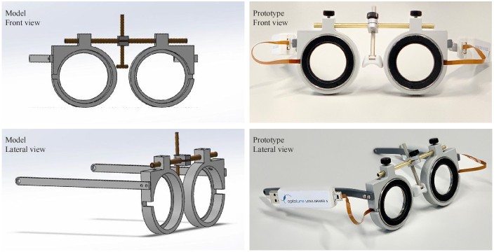
A visual demonstrator was developed with various off-the-shelf components and a custom-designed spectacle frame for fitting the tunable lens (EL-30-45, Optotune AG, Switzerland). The frame was designed such that the inter-pupillary distance (IPD) and lens height could be adjusted for each subject. The frame was designed preserving a typical spectacle frame design using computer-aided drawing software (Solidworks) and then produced using a 3D printer. The 3D model of the frame and the final prototype is shown in Fig. 2.
Fig. 2.
3D model of the frame and the final prototype for the visual demonstrator
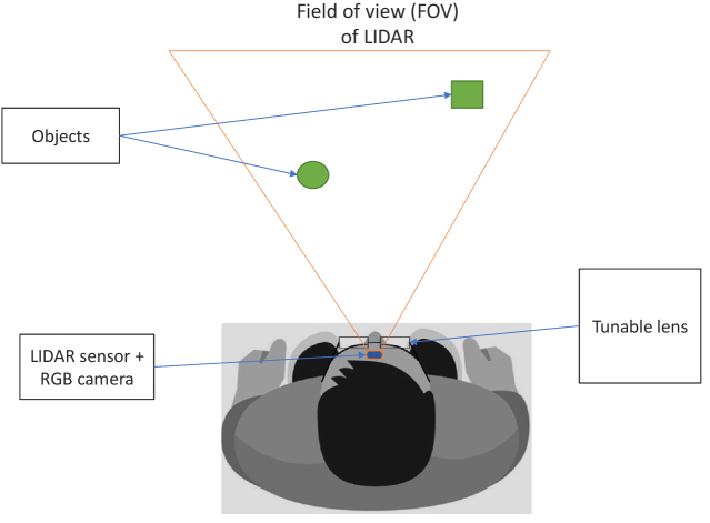
A feedback system using a LIDAR camera (L515, Intel Corporation, Seattle, USA) was used for determining distances in the visual field of subjects. This MEMS-based LIDAR camera is equipped with an RGB(Red-Green-Blue) sensor, proximity sensor, and gyroscope, which enables estimation of the distance from an object of interest and the head orientation of the subject. It was placed on the forehead of the subject using a custom-designed head strap which could be adjusted for various head sizes to ensure a comfortable and stable fit. A schematic diagram of the setup for optometric measurements in human subjects is shown in Fig. 3.
Fig. 3.
Schematic diagram of visual demonstrator and its components
2.3. Assessment of the setup for measurements in human subjects
2.3.1. Subjects
For determining the feasibility of the developed visual demonstrator, fifteen eye-healthy participants from the University Tuebingen with a mean age of years. The age range of the participants was between 22 - 37 years. Participants with ocular pathologies, corneal laser surgery or other ocular health issues were excluded. The experiments followed the tenets of the Declaration of Helsinki of 1964 and approval from the ethical board committee of the University of Tuebingen was obtained for this investigation. Informed consent was collected from all subjects after indications and potential consequences of the pharmaceutical agents and measurements had been explained in detail.
2.3.2. Pre-measurements
After signing the consent form and verification of the inclusion and exclusion criteria, the following device-related examinations were performed during an approximately 45-minute preliminary examination:
-
•
Objective measurement of the refractive error of the eye using wavefront aberrometry (ZEISS iProfiler plus, Carl Zeiss Vision GmbH, Aalen, Germany)
-
•
Habitual correction of the used spectacle lenses by the use of a digital lensmeter (ZEISS Visulens 500, Carl Zeiss Vision GmbH, Aalen, Germany)
-
•
Swept-source optical coherence tomography for imaging the anterior part of the eye (ZEISS PlexElite 9000, Carl Zeiss Meditec AG, Jena, Germany)
-
•
Optical biometry using swept-source optical coherence tomography to measure the length of the eye (ZEISS IOLMaster 700, Carl Zeiss Meditec AG, Jena, Germany)
-
•
Measurement of the inter-pupillary distance (IPD) using a Pupilometer
In order to block the ability of the participant’s eye to change its optical power, the use of a cycloplegic agent is indicated. Therefore, an ophthalmologic examination by an Ophthalmologist was performed prior to the inclusion of the participant to check for any contraindications. After successfully including the potential participants into the study, the Ophthalmologist administered the cycloplegic agent in order to reduce the accommodative ability of the participant’s eye using a pharmaceutical, Cyclopentolat (Approval Holder: Alcon Ophthalmika GmbH, Stella-Klein-Löw-Weg 17,1020 Wien). The visual demonstrator was then individualized for each participant by incorporating the individual IPD and correction of the measured habitual refractive error by using trial lenses (Trial Lens Cases BK 1; Oculus GmbH, Wetzlar, Germany). A pinhole of 3 mm was introduced to maintain uniform pupil size for all the subjects. The measurements were performed using tunable lenses (EL-30-45, Optotune AG, Dietikon, Switzerland). The EL-30-45 has a 30 mm clear aperture and dioptric power of 4.0 D.
2.3.3. Subject experiment
2.3.3.1. Visual acuity (VA)
Measurements for VA were performed while the subject was wearing the visual demonstrator and instructing the subject to perform the test using a program called Freiburg Visual Acuity and Contrast Test (FrACT - version 3.10.5). The test was shown on an external display (Retina Display, Apple Inc., California, USA) which was placed on a motorized stage that could be controlled using Arduino. The external display was connected to a personal computer(L590, Lenovo, Germany). Visual acuity was measured at three different distances(1.00 D, 1.25 D and 2.5 D with three repetitions at each distance. The optotype used was Landolt-C rings with eight different orientations, and the subject was asked to provide feedback using a keyboard for choosing the correct orientation. The focus (= the optical power of the tunable lens inside the demonstrator) was adjusted for the measured distance using the LIDAR sensor.
2.3.3.2. Contrast sensitivity (CS)
Similarly, the CS test was performed using the same computer program called Freiburg Visual Acuity and Contrast Test (FrACT – version 3.10.5) shown on the external display (Retina Display, Apple Inc., California, USA) placed at 1 m from the subject wearing the visual demonstrator. The Landolt-C rings were displayed in 8 different orientations on an external display (Retina Display, Apple Inc., California, USA) while connected to a personal computer (L590, Lenovo, Germany). The subject was asked to press the respective keys on the keyboard to give feedback about the direction of opening of the Landolt-C rings. The focus was fixed to the test distance of 1 m in the case of these measurements of CS.
2.3.3.3. Dynamic power estimation with LIDAR
An experimental setup was employed to understand the capabilities of the LIDAR camera and a control system for tuning the lens. The external display was translated on a motorized stage with a subject in a sitting position with the head on a chin-rest. The screen was translated over a range of 40 cm to 100 cm from the subject and the power was tuned in steps to the nearest of 0.25 D at randomized time intervals. The screen was detected in the scene using an image processing algorithm in real-time to determine an isolated rectangular region from the visual field. i.e., the screen. The centroid of the detected screen coordinates was calculated. The distance from the subject to the centroid coordinates 20 pixels was determined by using the data from the LIDAR sensor point-cloud data. Accordingly, the tunable lens power was set to the reciprocal of the determined distances during the translation of the screen over the course of time.
3. Results
3.1. Wavefront measurements
3.1.1. Linearity of the tunable lens
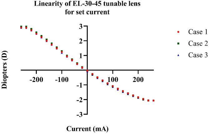
The lower-order aberrations were used to analyze the linearity of the tunable lens. The power of the lenses was varied in sequences from -240 mA to +240 mA and in the opposite directions as in cases 1 and 2, respectively, and then from 0 to 240 mA and 0 to -240 mA for case 3. It can be observed that the tunable lens shows a linear relationship between the set current and the measured focal power in the range of -2.25 D to + 2.00 D for all three cases (Fig. 4).
Fig. 4.
Linearity measurements of tunable lens for set current and measured focal power
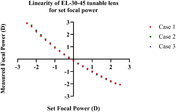
A similar linear trend is observed for set focal power and measured focal power measurements. It is linear for the measured linear power in the range of -2.25 D to + 2.00 D (Fig. 5) in a similar fashion for the current variation sequences. This trend of linearity ascertained that the tunable lenses could generate the required defocus for our application.
Fig. 5.
Linearity measurements of tunable lens for set and measured focal power.
A small hysteresis effect in power was observed during the measurements depending on the sequences of tuning the power of the lens (Fig. 6, 7). It was in the range of 0.5 D to 1.3 D. To ensure minimum differences between the set focal power or current and measured focal power, a lookup table was created by fitting a curve with the least squares method using these results to tune the lenses reducing the hysteresis effect to less than 0.2 D.
Fig. 6.
Zernike polynomials in m for high-order aberrations (HOA) measured for the tunable lens for change in set current.
Fig. 7.
Zernike polynomials in m for high-order aberrations (HOA) measured for the tunable lens for change in set focal power
3.1.2. Higher order aberrations
Furthermore, various higher order aberrations up to the 4th order were evaluated for the tunable lens. It was observed that in each case, the component Z8, which represents the vertical coma was pronounced, and this can be attributed to gravity affecting the fluid material of the tunable lens. A similar pattern was seen for the tunable lens irrespective of whether the variation of the input parameter for control of the tunable lens was input current or focal power in this software.
3.2. Visual acuity measurements
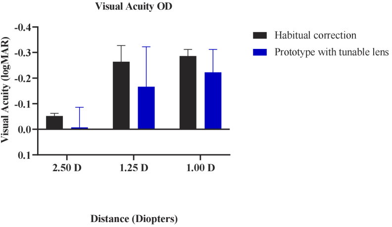
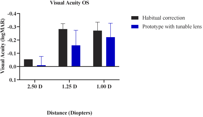
The visual acuity measurements depict the monocular results for each eye before and after cycloplegia for pre-presbyopic subjects. Considering the setup, the best visual acuity that could be reached was logMAR 0.27, -0.03, and -0.13 for distances of 2.50 D, 1.25 D, and 1.00 D, respectively. A higher visual acuity value than these best visual acuity values would represent a lower acuity.
It was observed that for the right eye, a lower mean visual acuity is observed for each of the distances with the prototype lens as compared to the normal correction (Fig. 8).
Fig. 8.
Visual acuity measurements of the right eye with the habitual correction and the prototype with tunable lenses.
Similarly, for the left eye, the visual acuity was reduced with the prototype (Fig. 9). But the resulting visual acuity with the prototype has a maximum of one line of visual acuity decrease, which would not affect the user’s vision as we are comparing it against the best possible visual acuity.
Fig. 9.
Visual acuity measurements of the left eye with the habitual correction and the prototype with tunable lenses.
3.3. Contrast sensitivity measurements
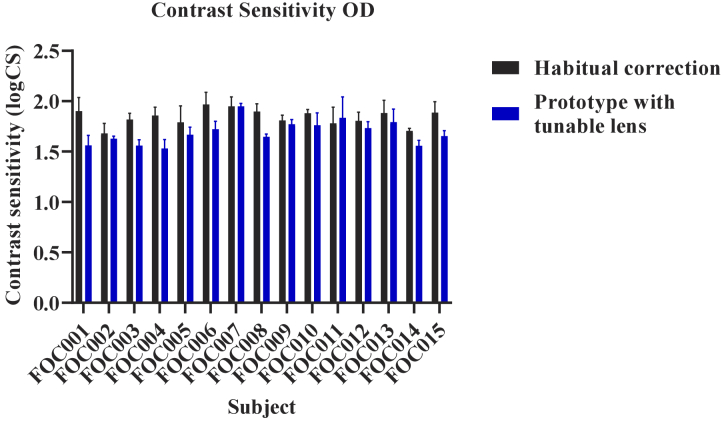
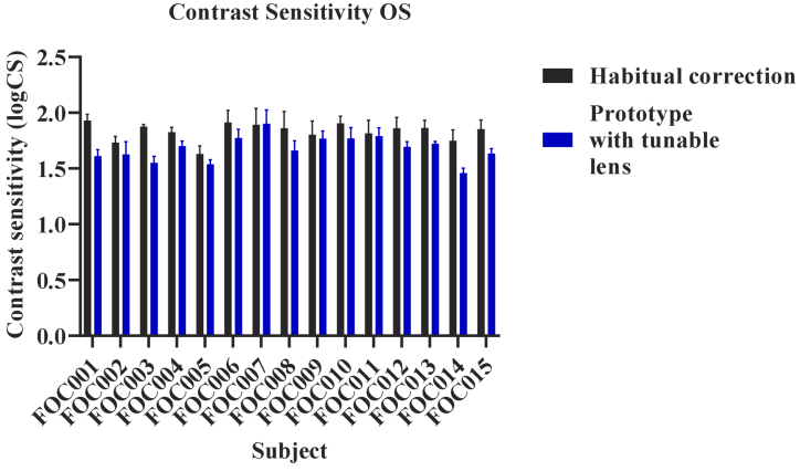
The monocular contrast sensitivity results were evaluated for each subject individually, comparing the normal correction and the prototype with tunable lens correction for both eyes (Fig. 10,11). It can be observed that the contrast sensitivity varied among individuals as well as between the two conditions.
Fig. 10.
Comparison of individual contrast sensitivity values for all subjects with normal correction and prototype with tunable lens for the right eye (OD).
Fig. 11.
Comparison of individual contrast sensitivity values for all subjects with normal correction and prototype with tunable lens for the left eye (OS).
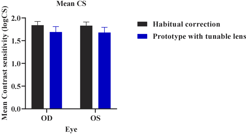
The mean contrast sensitivity was logCS 1.85 ± 0.13 and logCS 1.82 ± 0.12 for all subjects with their normal correction for the right eye and left eye, respectively (Fig. 12). The mean contrast sensitivity was logCS 1.67 ± 0.13 and logCS 1.68 ± 0.12 for all subjects with the prototype correction using the tunable lens for the right eye and left eye, respectively. There were also some subjects where the contrast sensitivity was equal for the prototype with the tunable lens as compared to their normal correction.
Fig. 12.
Comparison of mean contrast sensitivity values for all subjects with normal correction and prototype with the tunable lens.
3.4. Dynamic power estimation with LIDAR
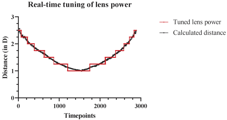
The tuning performance of the control system is shown in Fig. 13. The tuned power followed the translation of the screen in steps of 0.25 D. There was a latency of 40 ± 5 ms between the calculation of the distance – including detection of screen and distance from LIDAR point-cloud data and tuning of the lens. The tuning of the lens has a response time of less than 25 ms and a maximum settling time of 100 ms.
Fig. 13.
Real-time tuning of lens power as per distance calculated from LIDAR point-cloud data
4. Discussion
Presbyopia will affect about 25% of the world population by 2030 and involves every human being starting at the age of late 40s or early 50s; it becomes crucial to develop solutions that enable a more naturalistic visual behaviour and improve quality of life [1,16,17]. We demonstrate the feasibility of the developed prototype in terms of optical quality as well as a subject study to evaluate ophthalmic parameters such as visual acuity and contrast sensitivity. We designed and built a visual demonstrator for evaluating the efficacy of a solid-state LIDAR-based mechanism to control tunable lenses as a first step towards mimicking the natural accommodation mechanism. In this study, we are trying to demonstrate that the LIDAR camera has better accuracy and range and a reasonable latency to be used as a 3D distance estimator. For determining the object of interest for a person, various methods could be employed in the real-world scenario such as vergence or gaze-tracking, as defined in the literature. [14,15]
The tunable lens technology is currently an area of active research which is constantly evolving. At the current stage, the liquid membrane-based tunable lenses seem to outperform the existing technologies in terms of big clear aperture and smaller lower order and higher order aberrations as shown in this study. Existing technology such as the Alvarez lenses have been shown to induce astigmatism errors upto 0.50 D and higher order aberrations. [18] The other tunable lens technologies such as liquid crystal diffractive lenses have an aperture of 30 mm but the power change is limited to only +1.00 D with a settling time of under 1 second or a smaller lens with only 6 mm diameter with maximum +3.00 D with a settling time of under 100 ms. [19] This range of dioptric power is lower, and the settling time is higher than the liquid membrane-based tunable lens in this study.
As shown in the wavefront aberrometry results, the optical properties of the liquid lenses used in this study are suitable for the visual demonstrator. A small hysteresis effect in power was observed during the measurements depending on the sequence of tuning the power of the lens, which is in accordance with the previous literature [20]. It was in the range of 0.5 D to 1.3 D. To resolve this problem, 1000 randomly selected values of current were used to tune the tunable lens and the focal power was measured using the Hartmann-Shack wavefront sensor. Subsequently, a lookup table was created by fitting a curve with the least squares method using these results to tune the lenses to reduce the hysteresis effect to less than 0.2 D. This method enabled precise control over the spherical power in the lens which is vital for this application to avoid discomfort for subjects.
The frame has been developed keeping in mind the general design of spectacles, unlike previous studies where the design is similar to ski goggles or virtual reality headsets [14,15]. Previous studies for tunable lens-based eyewear have employed feedback systems such as single-pixel TOF sensors or depth cameras compared to the solid-state LIDAR camera used in this study [10,15]. TOF sensors-based feedback mechanisms need the subject to move its head towards the particular object of interest to calculate distance. The use of depth cameras by Padmanabhan et al. (2019) solves this particular issue; however, the depth resolution of LIDAR cameras along the z-axis is better than that of stereo cameras [21–23]. The LIDAR camera can provide over 23 million accurate depth pixels per second, with a resolution of 1024 x 768 at 30 frames per second over a range of 0.20 to 9.00 m which is much greater than the accommodative requirement for presbyopes [21]. Furthermore, the LIDAR camera has other sensors such as an RGB sensor and an inertial measurement unit (IMU) that could be utilized for head tracking to optimize the control loop further for tuning of these lenses. The current work demonstrates the capability of using a solid state LIDAR system in real-time for tuning the lenses effectively for presbyopia correction without compromising the optical quality. The form factor of the LIDAR could be miniaturized for the visual demonstrator over the course of time.
Healthy subjects were used in this study to understand their optical performance when the natural accommodative ability is restricted by cycloplegia drops but assisted by the tunable lens. With healthy cycloplegic subjects, we have almost no residual accommodation in each subject, meaning that the subject is completely dependent on the tunable system for focusing on near objects. For presbyopic subjects, the residual accommodation varies among subjects depending on age. [24–26] This could be accounted for in the further stage of the development of the prototype for the correction of presbyopia. The visual acuity and contrast sensitivity results obtained in this study are either similar to or better than previous studies employing tunable lenses. These results could be attributed to the fact that we have healthy cycloplegic subjects as compared to presbyopic subjects used in the previous studies. But this also implies that the performance of the liquid lenses is sufficient to be used for refractive correction in presbyopes as there was no significant difference between the visual acuity and contrast sensitivity for normal correction (or emmetropic subjects) against using the tunable lens under cycloplegia.
5. Conclusion
Using a solid-state LIDAR camera along with tunable lenses showed technical feasibility for their use as a 3D distance estimator in the development of correction spectacles for presbyopia. Low wavefront errors, fast switching of powers along with a wide field of view of these tunable lenses demonstrate a significant potential of these lenses for ophthalmic applications. Further investigations are required, including presbyopic and pre-presbyopic subjects, to evaluate the visual demonstrator in a more holistic approach towards restoring natural accommodation ability. The developed algorithm with solid-state LIDAR opens new horizons in the field of tunable lens driving algorithms, which could enable these lenses to be utilized in real-world scenarios.
Funding
Deutsche Forschungsgemeinschaft10.13039/501100001659 (DFG) SFB 1233, Robust Vision:Inference Principles and Neural Mechanisms, TP TRA, Project number: 276693517; Deutsche Forschungsgemeinschaft and Open Access Publishing Fund of the University of Tuebingen; European Union’s Horizon 2020 research and innovation program (951910).
Disclosures
We declare that Olga Lukashova-Sanz and Siegfried Wahl are scientists at the University of Tübingen and employees of Carl Zeiss Vision International GmbH, as detailed in the affiliations. The authors declare that the research was conducted in the absence of any commercial or financial relationships that could be construed as a potential conflict of interest.
Data availability
Data underlying the results presented in this paper are not publicly available at this time but may be obtained from the authors upon reasonable request.
References
- 1.Fricke T. R., Tahhan N., Resnikoff S., Papas E., Burnett A., Ho S. M., Naduvilath T., Naidoo K. S., “Global prevalence of presbyopia and vision impairment from uncorrected presbyopia: systematic review, meta-analysis, and modelling,” Ophthalmology 125(10), 1492–1499 (2018). 10.1016/j.ophtha.2018.04.013 [DOI] [PubMed] [Google Scholar]
- 2.David G., Pedrigi R. M., Humphrey J., “Accommodation of the human lens capsule using a finite element model based on nonlinear regionally anisotropic biomembranes,” Comput. Methods Biomech. Biomed. Eng. 20(3), 302–307 (2017). 10.1080/10255842.2016.1228907 [DOI] [PubMed] [Google Scholar]
- 3.Garner W. H., Garner M. H., “Protein disulfide levels and lens elasticity modulation: applications for presbyopia,” Invest. Ophthalmol. Visual Sci. 57(6), 2851–2863 (2016). 10.1167/iovs.15-18413 [DOI] [PMC free article] [PubMed] [Google Scholar]
- 4.Heys K. R., Cram S. L., Truscott R. J., “Massive increase in the stiffness of the human lens nucleus with age: the basis for presbyopia?” Molecular vision 10, 956 (2004). [PubMed] [Google Scholar]
- 5.Glasser A., Campbell M. C., “Biometric, optical and physical changes in the isolated human crystalline lens with age in relation to presbyopia,” Vision Res. 39(11), 1991–2015 (1999). 10.1016/S0042-6989(98)00283-1 [DOI] [PubMed] [Google Scholar]
- 6.Charman W. N., “Developments in the correction of presbyopia i: spectacle and contact lenses,” Ophthalmic Physiol Opt 34(1), 8–29 (2014). 10.1111/opo.12091 [DOI] [PubMed] [Google Scholar]
- 7.Pérez-Prados R., Pi nero D. P., Pérez-Cambrodí R. J., Madrid-Costa D., “Soft multifocal simultaneous image contact lenses: a review,” Clin. Exp. Optom. 100(2), 107–127 (2017). 10.1111/cxo.12488 [DOI] [PubMed] [Google Scholar]
- 8.Hossain P., Barbara R., “The future of refractive surgery: presbyopia treatment, can we dispense with our glasses?” Eye 35(2), 359–361 (2021). 10.1038/s41433-020-01172-8 [DOI] [PMC free article] [PubMed] [Google Scholar]
- 9.Alvarez L. W., “Two-element variable-power spherical lens,” (1967). US Patent 3, 305, 294.
- 10.Hasan N., Karkhanis M., Khan F., Ghosh T., Kim H., Mastrangelo C. H., “Adaptive optics for autofocusing eyeglasses,” in Applied Industrial Optics: Spectroscopy, Imaging and Metrology , (Optical Society of America, 2017), pp. AM3A–1. [Google Scholar]
- 11.Wapler M. C., “Ultra-fast, high-quality and highly compact varifocal lens with spherical aberration correction and low power consumption,” Opt. Express 28(4), 4973–4987 (2020). 10.1364/OE.382472 [DOI] [PubMed] [Google Scholar]
- 12.Jarosz J., Molliex N., Chenon G., Berge B., “Adaptive eyeglasses for presbyopia correction: an original variable-focus technology,” Opt. Express 27(8), 10533–10552 (2019). 10.1364/OE.27.010533 [DOI] [PubMed] [Google Scholar]
- 13.Hasan N., Banerjee A., Kim H., Mastrangelo C. H., “Tunable-focus lens for adaptive eyeglasses,” Opt. Express 25(2), 1221–1233 (2017). 10.1364/OE.25.001221 [DOI] [PMC free article] [PubMed] [Google Scholar]
- 14.Mompeán J., Aragón J. L., Artal P., “Portable device for presbyopia correction with optoelectronic lenses driven by pupil response,” Sci. Rep. 10, 1–9 (2020). 10.1038/s41598-020-77465-5 [DOI] [PMC free article] [PubMed] [Google Scholar]
- 15.Padmanaban N., Konrad R., Wetzstein G., “Autofocals: Evaluating gaze-contingent eyeglasses for presbyopes,” Sci. Adv. 5(6), eaav6187 (2019). 10.1126/sciadv.aav6187 [DOI] [PMC free article] [PubMed] [Google Scholar]
- 16.Patel I., Munoz B., Burke A. G., Kayongoya A., Mchiwa W., Schwarzwalder A. W., West S. K., “Impact of presbyopia on quality of life in a rural african setting,” Ophthalmology 113(5), 728–734 (2006). 10.1016/j.ophtha.2006.01.028 [DOI] [PubMed] [Google Scholar]
- 17.Mancil G. L., Bailey I. L., Brookman K. E., Bart Campbel J., Cho M. H., Rosenbloom A. A., Sheedy J. E., Optometric Clinical Practice Guideline: Care of the Patient with Presbyopia (American Optometric Association, 2011). [Google Scholar]
- 18.Radhakrishnan H., Charman W. N., “Optical characteristics of alvarez variable-power spectacles,” Physiol. Opt. 37(3), 284–296 (2017). 10.1111/opo.12361 [DOI] [PubMed] [Google Scholar]
- 19.Milton H. E., Van Heugten A., “70-2: Invited paper: Developments in electroactive lens technology for vision correction,” SID Symp. Dig. Tech. Pap. 50(1), 989–991 (2019). 10.1002/sdtp.13092 [DOI] [Google Scholar]
- 20.Suchkov N., Fernández E. J., Artal P., “Wide-range adaptive optics visual simulator with a tunable lens,” J. Opt. Soc. Am. A 36(5), 722–730 (2019). 10.1364/JOSAA.36.000722 [DOI] [PubMed] [Google Scholar]
- 21.Intel ® RealSense TM LiDAR Camera L515 Datasheet (2021).
- 22.Intel ® RealSense™ Camera R200 Embedded Infrared Assisted Stereovision 3D Imaging System with Color Camera Product Datasheet R200 (2016).
- 23.Servi M., Mussi E., Profili A., Furferi R., Volpe Y., Governi L., Buonamici F., “Metrological characterization and comparison of d415, d455, l515 realsense devices in the close range,” Sensors 21(22), 7770 (2021). 10.3390/s21227770 [DOI] [PMC free article] [PubMed] [Google Scholar]
- 24.Hamasaki D., Ong J., Marg E., “The amplitude of accommodation in presbyopia,” Am. Journal Optometry Archives Am. Acad. Optom. 33(1), 3–14 (1956). 10.1097/00006324-195601000-00002 [DOI] [PubMed] [Google Scholar]
- 25.Donders F. C., On the Anomalies of Accommodation and Refraction of the Eye (New Sydenham Society, 1864). [Google Scholar]
- 26.Duane A., “Normal values of the accommodation at all ages,” J. Am. Med. Assoc. LIX(12), 1010–1013 (1912). 10.1001/jama.1912.04270090254042 [DOI] [Google Scholar]
Associated Data
This section collects any data citations, data availability statements, or supplementary materials included in this article.
Data Availability Statement
Data underlying the results presented in this paper are not publicly available at this time but may be obtained from the authors upon reasonable request.


