Abstract
Purpose
Introduce Shimming Toolbox (https://shimming-toolbox.org), an open-source software package for prototyping new methods and performing static, dynamic and real-time B0 shimming as well as B1 shimming experiments.
Methods
Shimming Toolbox features various field mapping techniques, manual and automatic masking for the brain and spinal cord, B0 and B1 shimming capabilities accessible through a user-friendly Graphical User Interface (GUI). Validation of Shimming Toolbox was demonstrated in three scenarios: (i) B0 dynamic shimming in the brain at 7 T using custom AC/DC coils, (ii) B0 real-time shimming in the spinal cord at 3 T, and (iii) B1 static shimming in the spinal cord at 7 T.
Results
The B0 dynamic shimming of the brain at 7 T took about 10 minutes to perform. It showed a 47% reduction in the standard deviation of the B0 field, associated with noticeable improvements in geometric distortions in EPI images. Real-time dynamic xyz-shimming in the spinal cord took about 5 minutes and showed a 30% reduction in the standard deviation of the signal distribution. B1 static shimming experiments in the spinal cord took about 10 minutes to perform and showed a 40% reduction in the coefficient of variation of the B1 field.
Conclusion
Shimming Toolbox provides an open-source platform where researchers can collaborate, prototype and conveniently test B0 and B1 shimming experiments. Future versions will include additional field map preprocessing techniques, optimization algorithms and compatibility across multiple MRI manufacturers.
Keywords: MRI, Shimming, inhomogeneities, B0, B1, parallel transmit, open-source software, Python
Introduction
In a quest for better magnetic resonance (MR) images, scanners have gotten ever more powerful by increasing the main source of signal in MR imaging (MRI), the B0 field. A higher B0 field increases signal-to-noise ratio (SNR) and contrast to noise ratio (CNR), allowing one to image at a higher spatial and/or temporal resolution. However, stronger magnets also introduce their own challenges; the increased inhomogeneity of the B0 field when scanning the human body (1) as well as inhomogeneities of the B1 field (2). These issues, and potential solutions to address them, are described hereafter.
B0 shimming
B0 inhomogeneities lead to artifacts such as geometric distortions in echo planar imaging (EPI) images (3), signal loss from intravoxel T2* dephasing, disruption of frequency selective RF pulses such as fat saturation pulses (4), ghosting (5), signal overlap and others. To reduce these artifacts, it is necessary to homogenize the B0 field, a procedure known as B0 shimming.
Passive shimming, which consists of adding pieces of ferromagnetic objects to change the magnetic field in the scanner, does not allow for the correction of patient specific inhomogeneities. However, active shimming, which consists of updating the currents sent to specialized coils, provides the necessary functionalities to mitigate those inhomogeneities.
Active shimming is typically performed by acquiring a ΔB0 field map, which describes the offset from the nominal B0 field. This field map is used along with coils and a shimming region of interest (ROI) to calculate the currents (or shim coefficients) that should be used to achieve an optimal B0 field. Different techniques and coils have been developed over the years to improve active B0 shimming.
Active shimming techniques
Static (or global) shimming:
Optimize shim currents for a specified volume of interest. These currents stay the same throughout an acquisition. This is the most popular shimming technique.
Dynamic shimming:
The shim currents are optimized separately for each slice to be acquired. This technique requires rapid changes of the shim currents over the course of an acquisition, adding constraints on the shim coils. Dynamic shimming was shown to further improve image quality when compared to static shimming (6,7).
Real-time shimming:
The shim currents are modulated over time to compensate for time-varying B0 field, which could occur with breathing (5,8).
Coils used for shimming
Spherical harmonics:
Scanners are equipped with coils that produce fields that follow the spherical harmonic (SH) expansion. Scanners typically have 1st (gradient coils), 2nd and sometimes 3rd order shim coils. Moreover, dynamic shimming is usually restricted to the 1st order due to the high inductance of higher order coils, inducing undesired eddy currents when switching them rapidly (9,10). The low order of SH in MRI scanners limit their effectiveness since it can only reduce field offset patterns of low spatial variability.
External shim coils:
Shim-only coils can supplement the existing SH-based coil systems of the scanner to provide additional degrees of freedom and shimming performance. These are typically located close to the imaging target and are designed to achieve a desired field geometry and strength (8,11,12).
AC/DC coils:
These coils combine the functionality of reception (Rx) and/or transmission (Tx), and shimming of the magnetic field in a single coil. A notable advantage of AC/DC coils compared to external shim coils is that they are closer to the region of interest, further improving shimming performance (13,14).
B1+ shimming
As the field strength increases, the RF wavelength decreases. At 7 T, this wavelength is around 12 cm, inducing an inhomogeneous excitation profile known as B1+ inhomogeneities. These inhomogeneities result in a spatially varying flip angle over the image, yielding artifacts/challenges such as variations of tissue contrast, improper inversion pulses, non-optimal fat saturation and excessive specific absorption rate (SAR) (15,16).
By measuring the B1+ distribution generated by the different transmit elements in the patient’s body (procedure known as B1+ mapping), one is able to find a set of optimal shim weights (phase and magnitude of the excitation pulses) that, when applied to the MRI sequence, results in an improved B1+ homogeneity, and therefore a more uniform image intensity and contrast. This process is commonly referred to as B1+ static (or global) shimming, i.e., the whole volume of interest is shimmed simultaneously and the shim-weights are not modified throughout the sequence. Analogous to B0 shimming, one can also perform B1+ dynamic and real-time shimming, but as those are not yet implemented in Shimming Toolbox, we will not consider them further. For the sake of clarity, in the rest of the manuscript we will use the term ‘B1’ when referring to ‘B1+’.
Objectives
To apply and optimize the B0 and B1 shimming techniques reviewed above, a proper software ecosystem is required. While the software console that comes with the MR system can perform basic B0 and B1 shimming, the more advanced techniques are often not available (especially those based on external/custom shim coils). Moreover, shimming algorithms can vary across manufacturers and their implementation is partially opaque (for proprietary reasons), hampering the standardization and transparency of shimming methods. While some freely available toolboxes exist for B0 shimming (B0 Detox (17), Harmonized (18)) and B1 shimming (Parallel Transmission RF Shimming GUI (19), cardiac_RF_shimming (20)), to the best of our knowledge, there is no open-source all-in-one software that can accommodate a variety of B0 and B1 shimming experiments. Here we introduce Shimming Toolbox (https://shimming-toolbox.org), an open-source software package for prototyping new methods and performing static, dynamic and real-time B0 as well as RF shimming experiments. We validated Shimming Toolbox for B0 shimming on different coils (scanner SH, 31 channel AC/DC array (21)), different field strengths (3 T and 7 T), two different imaging sites, different users and different techniques (dynamic, real-time). We also validated the toolbox for B1 global shimming. Both B0 and B1 shimming experiments were conducted on healthy participants.
Methods
Overview of Shimming Toolbox
Shimming Toolbox is installed on a separate computer running macOS or Linux (Windows support is planned). Shimming Toolbox can be used ‘offline’ with already acquired data, or it can be connected to the scanner and process shim coefficients during an imaging session. In the latter case, the laptop running Shimming Toolbox is connected under the same VLAN as the MRI console and a disc is mounted so that images are readily accessible on the laptop for processing.
Shimming Toolbox is written in Python and has been designed to be used on the command line with simple calls to its different functionalities. A Graphical User Interface (GUI) is also available in the form of a plugin to FSLeyes (22) which offers an intuitive way to use the toolbox, look through data and verify shimming outputs. Figure 1 shows an overview of Shimming Toolbox. Detailed functionalities are described in the subsequent sections.
Figure 1:
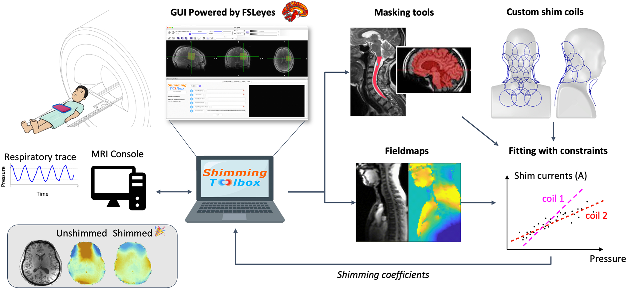
Overview of Shimming Toolbox. The toolbox is installed on a computer and can be connected directly to the scanner console to access the images as they are reconstructed. Shimming Toolbox can calculate field maps, define masks and create shim coil calibration profiles, optimize B0 and B1 shim currents and send the currents to the MRI scanner in predefined format. The bottom right panel illustrates a respiratory-modulated real-time shimming scenario, wherein the shim current for each coil element is dependent on a pressure probe that relates to the patient’s respiratory trace. The coefficients are then sent to the scanner or to the custom coil drivers.
Convert DICOM to NIfTI files
The first step consists in converting the acquired data into a common format that will be used throughout the different steps of the processing pipeline. We chose the NIfTI format because of its popularity and ease of access to its metadata. DICOM data is converted using dcm2niix (23) and subsequently organized into the Brain Imaging Data Structure (BIDS) (24,25) using dcm2bids (26). Advantages of the BIDS structure is that imaging and field map files are separated into separate folders and their properties, useful for shimming experiments, are well described by a JSON sidecar.
Create B0 field maps
Shimming Toolbox supports single NIfTI file phase difference input as well as dual-echo input by computing the complex ratio of the two echoes. We have plans to support more echoes and techniques in the future. Phase images are spatially unwrapped using FSL’s prelude (27) as an external dependency. Future support for other unwrappers such as UMPIRE (28) and ROMEO (29) is planned. If images do not need unwrapping (e.g., the sequence already does it), this step can simply be skipped and unwrapped fieldmaps can be input into Shimming Toolbox. Field maps acquired through different timepoints (4D) are also supported, allowing for seamless processing of a time series of field maps.
Create B0 coil profiles
B0 coil profiles describe the geometry of the z-component of the static magnetic field generated by each shim coil element. Shimming Toolbox includes a comprehensive pipeline to generate B0 coil profiles for MRI-system based (i.e., gradient and shim coils) and custom coils.
To create coil profiles for gradient/shim systems integrated in the MR scanner, we use SH functions to generate the different orders available in the scanner. These are computed at runtime to accommodate the different coordinate systems used by different scanner manufacturers.
To create coil profiles for custom shim coils, the user runs a series of ΔB0 field map scans with different currents for each of their coil channels. These field maps are then processed by linearly fitting field offsets with input currents, coil wise. The output is a NIfTI file containing the coil profiles for each channel, and a JSON file describing the different constraint parameters of the coils (e.g., maximum current per channel, total current allowed by the amplifiers).
Create masks
Masks define the spatial region where B0 or B1 shimming should be optimized. Manual masking is possible via FSLeyes GUI to create different shapes and select specific ROIs. Masks can also be created automatically in the brain using Brain Extraction Tool (BET) (30) or in the spinal cord using the Spinal Cord Toolbox (SCT) (31). These scenarios are illustrated in Figure 2. If the target image (see below) on which to apply shimming is of low quality (e.g., gradient echo EPI at coarse resolution), an anatomical image can be acquired and displayed in the FSLeyes GUI for a more accurate masking procedure. If necessary, a co-registration between the target image and the anatomical image can be performed before proceeding with masking. The parameters of BET and SCT can also be changed to adjust the segmentation. Masks can be combined (i.e., target image and field map) and eroded/dilated to achieve the right ROI.
Figure 2:
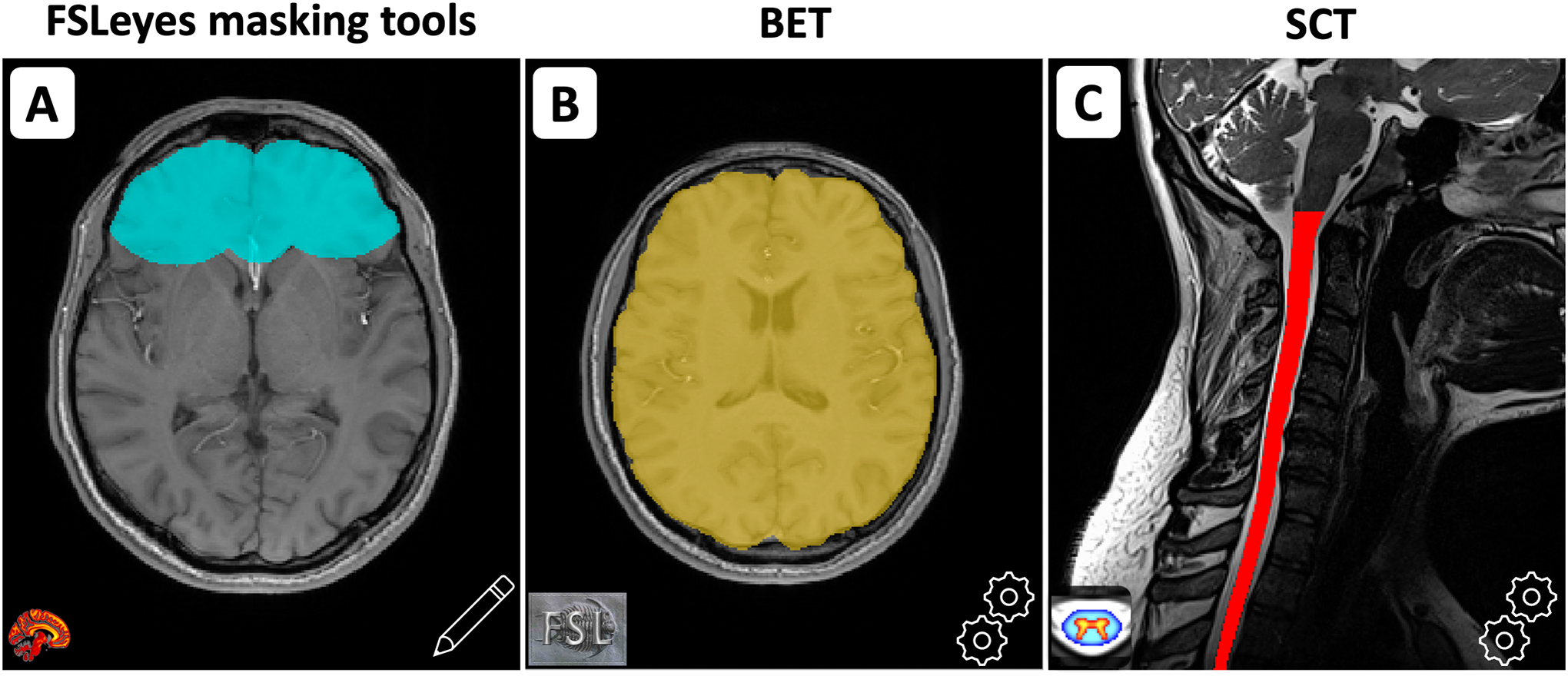
A) Manual creation of a mask using FSLeyes’ existing interface. B) Creation of a brain mask using FSL BET. C) Creation of a spinal cord mask using SCT.
B0 shimming
Static shimming
The required inputs are: (i) a ΔB0 field map, (ii) a target image, (iii) a mask, (iv) shim coil profiles and their respective constraints. The target image is used to obtain the image geometry and acquisition orientation for which shimming will be optimized. The target image can be the same sequence as the one to be shimmed or one with minimal scan time and the same above-mentioned parameters.
The mask and coil profiles are resampled to match the ΔB0 field map, so that the optimization is computed at the resolution of the ΔB0 map. An optional dilation step on the mask is possible to increase the size of the mask and include more voxels for the optimization.
Shimming Toolbox features a sequential least square programming solver that minimizes a desired criterion, such as the mean squared error (MSE), the mean absolute error (MAE) or the standard deviation (STD) of the ΔB0 field in the selected ROI. An additional L1 regularization term can be specified to penalize converging solutions that require a high current per channel (or across channels), which is particularly useful in a B0 dynamic shimming scenario (see below) where current rapidly varies across slices. Using the coil-specific constraints, currents can be limited to respect coil limits.
Dynamic shimming
In dynamic shimming, each slice is subject to a specific set of shim coefficients. This mode is only available for 2D multi-slice acquisitions. The required inputs are the same as those for static shiming, and the pipeline differs in that each slice is optimized independently. The slice ordering information is automatically parsed from the target image (via the JSON sidecar) to output the coefficients correctly for ascending, descending, interleaved and simultaneous multi-slice acquisitions. In the latter case of simultaneous multi-slice (also called multiband), shimming will be optimized across the slices that are being simultaneously excited and acquired.
The coil profiles are resampled on the ΔB0 field map. The mask is used along with the slice information to create multiple masks containing the ROI for each slice. Each slice of the mask is then individually resampled on the field map. A dilation step of each resampled sliced mask (or ROI) is particularly useful in dynamic shimming if using thin slices, as this adds more pixels for optimization in the through-slice direction.
The ΔB0 field is optimized for each slice in the ROI, yielding coefficients that will minimize the selected criterion. The pipeline for static and dynamic shimming is summarized in Figure 3.
Figure 3:
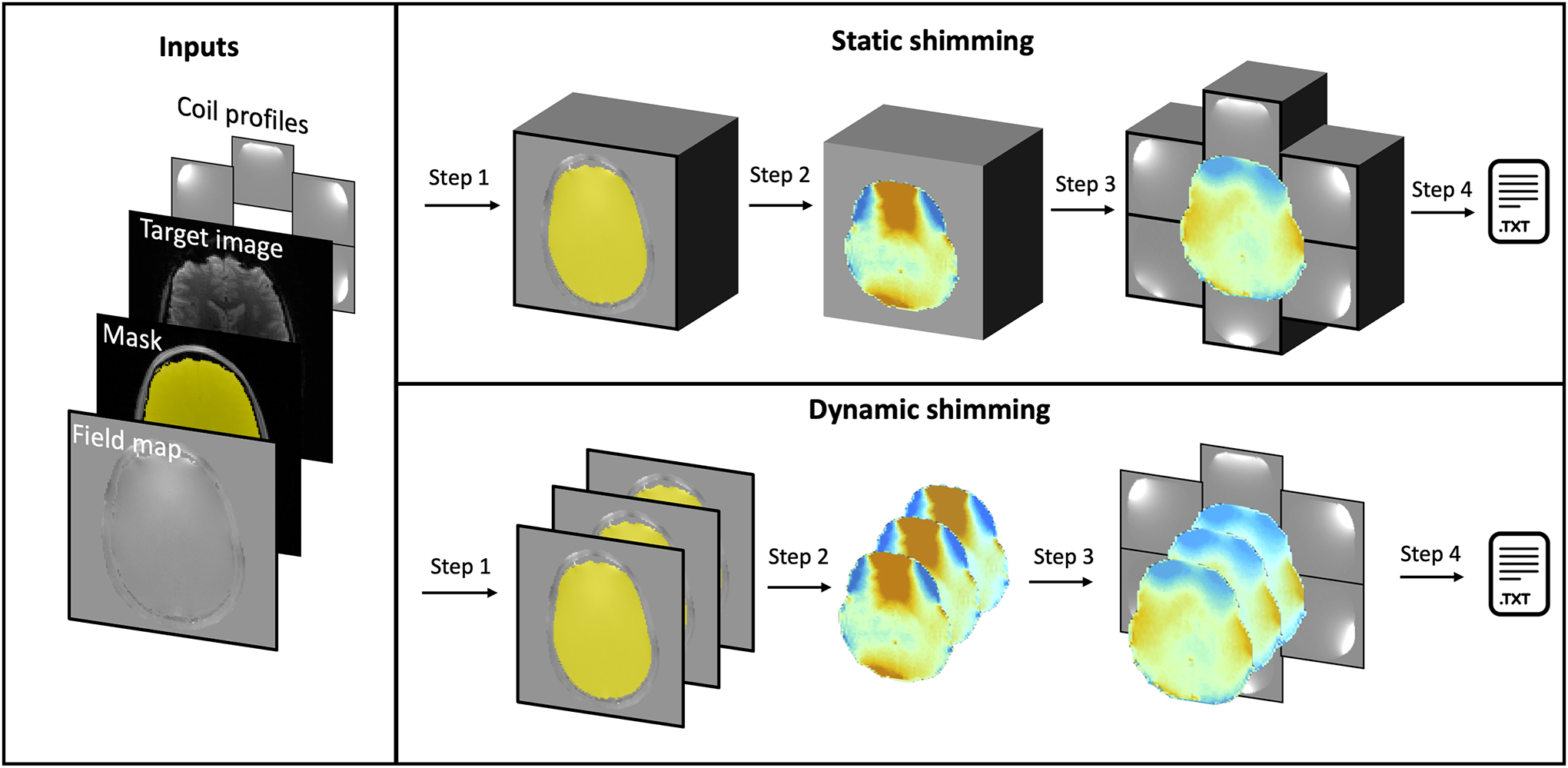
Overview of B0 static and dynamic shimming. Inputs: Both static and dynamic shimming require (i) a ΔB0 field map, (ii) a target image, (iii) a mask, (iv) shim coil profiles and their respective constraints. Step 1: The mask is either considered as a single block (static) or multiple slice groups (dynamic), and resampled to the ΔB0 field map space. Step 2: The ROI of the field map is extracted using the mask. Step 3: The coil profiles are resampled to the field map space and shimming coefficients are calculated based on the selected solver and criterion. Step 4: The coefficients are written to a text file.
Real-time dynamic shimming
In real-time shimming, the goal is to correct for both the static (non time-varying) and time-varying parts of the magnetic field. Coefficients can be calculated globally or for each slice (dynamic). An implementation of real-time shimming was developed to correct for breathing-related time-varying magnetic fields. Multiple ΔB0 field maps are acquired over time (e.g., while the participant is breathing), while an external signal is being recorded (e.g., chest motion via pressure readings from bellows). The inputs are (i) a 4D ΔB0 field map, (ii) a 3D target image, (iii) a mask, (iv) coil profiles and (v) a probe that tracks breathing pattern (e.g., respiratory bellows). More time points in the acquired 4D ΔB0 map will ensure a more robust fit, at the expense of scan time. We have observed good results using 30 timepoints spanning more than 10 breathing cycles. The pressure probe should have a temporal resolution of at least the TR in gradient echo (GRE) acquisitions to update the pressure for each line of k-space.
The probe signal of pressure over time, P(t), is used alongside the field maps to extract the static and real-time component of the ΔB0 field, for each voxel, through a linear fit. The mask is separated in slices and each slice is resampled on the field map. Two optimizations are then performed: (i) on the static component to find the coefficients that best fit the static profile, and (ii) on the real-time component to find the coefficients that best fit the real-time profile. These yield Coefstatic and Coefreal-time for each slice and each channel.
During shimming, P(t) is read at the time of the RF pulse (t′). Coefstatic and Coefreal-time of the slice being acquired for each coil channel are used to evaluate the following equation and calculate Coef of each channel which will be applied for that read-out. If the subject breathes more deeply than in the 4D field mapping sequence, a proper shim estimation is still provided since Coef scales linearly with pressure.
When using the scanner’s gradient coil as shim coils, x, y and z gradients can be calculated from P(t′). Figure 4 shows a pulse sequence diagram of a custom multi-echo GRE sequence demonstrating how x, y and z gradients can be used with the described method to achieve real-time dynamic xyz-shimming.
Figure 4:
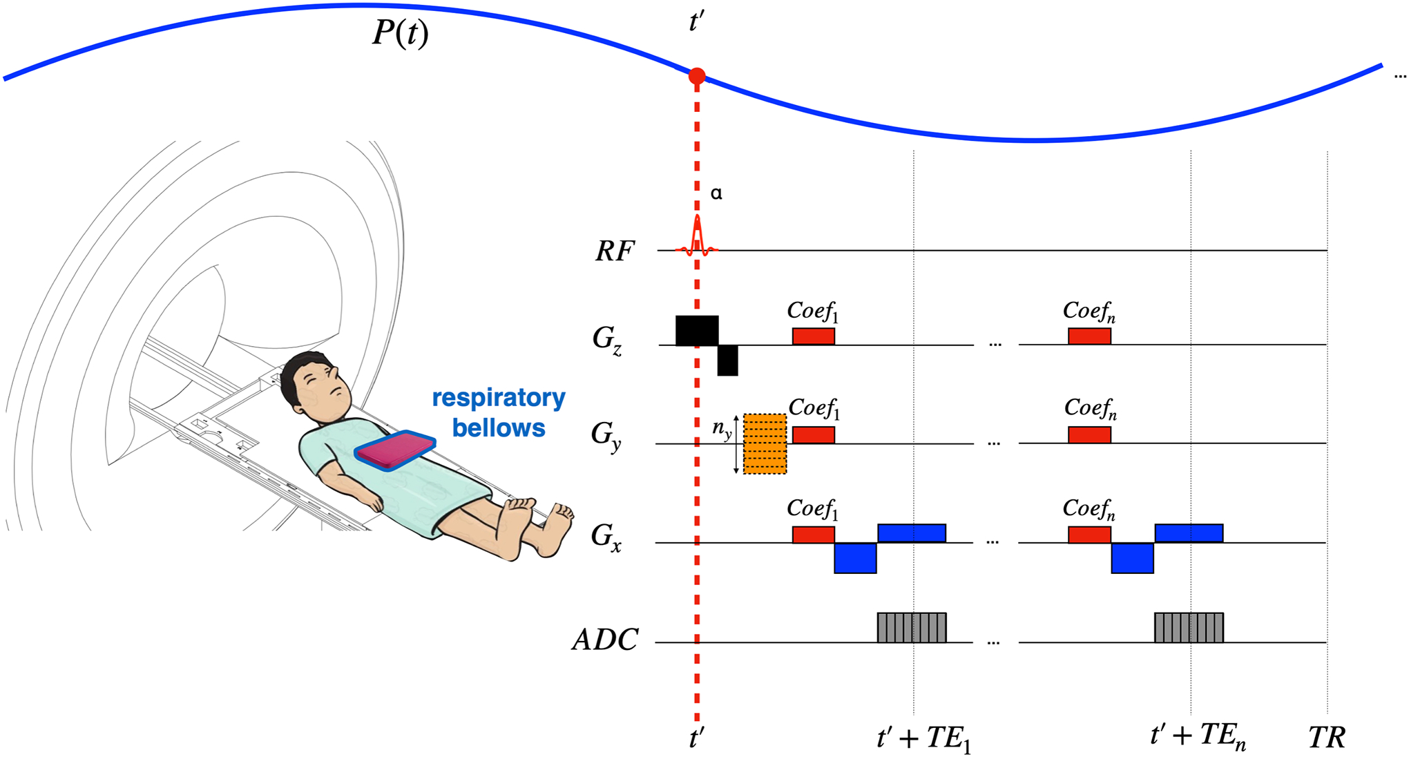
Real-time dynamic xyz-shimming sequence showing one line of k-space. Gradients (in red) along x, y and z are played out during the pulse sequence to correct for through-slice and in-plane inhomogeneities. The amplitude of these gradients is modulated in real-time by the respiratory pressure trace. Note that the pressure reading was purposely made faster for illustration purposes (one TR is much shorter than one breathing cycle).
B1 shimming
Performing B1 shimming using a multi-transmit coil requires prior knowledge of both the magnitude and phase of the B1 field generated by each transmit (Tx) element. From there, an optimization of the magnitude and phase values (shim weights) of the excitation waveforms sent to the different Tx elements can be performed to control the RF interferences and mitigate B1 inhomogeneities. To date, Shimming toolbox offers B1 static shimming, i.e., a single set of NTx shim weights (where NTx is the number of transmit elements) is optimized over the provided shimming ROI and is used over the whole imaging sequence.
To date, four different B1+ shimming algorithms fulfilling various needs are included in Shimming Toolbox:
Reduction of the coefficient of variation: Minimizes the STD of the B1 magnitude divided by its mean, in order to homogenize it over the ROI. High B1 efficiencies are favored, with respect to safety guidelines.
Targeting a specific B1 efficiency: The algorithm performs a magnitude least square optimization to target a B1 efficiency provided by the user. The B1 efficiency corresponds to the measured B1 (in μT) scaled by the reference excitation voltage applied at the scanner (in V, corresponds to the total voltage for all channels). It is therefore expressed in T/V.
Phase-only shimming: Only optimizes the phase of the excitation waveforms sent to the Tx elements. This optimization is fast and does not modify the power sent to the Tx system, but it results in a sub-optimal homogeneity compared to complex optimizations.
Specific Absorption Rate efficiency: seeks to maximize the SAR efficiency, defined as the ratio of the mean B1 efficiency and the square root on the maximum local SAR value (32).
Outputs
Shimming coefficients are written to a text file that can be read by a pulse sequence and/or by external shim-coil software. The format of the text file can be customized to accommodate the required input style and output coordinate system (e.g., different manufacturers and/or methods). Typical examples of output text files are shown in Figure 5.
Figure 5:
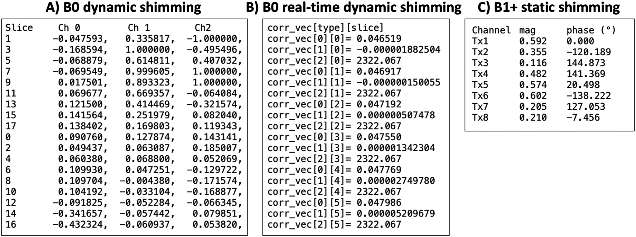
Example text files output by Shimming Toolbox. A) Text file to be read by an Arduino Teensy board in the case of custom shim coils during B0 dynamic shimming (13). The slices were acquired in an interleaved fashion and are chronologically written to the text file. Each row corresponds to a slice and each column a coil channel. B) Text file to be read by the pulse sequence during B0 real-time dynamic shimming. Each block of three rows corresponds to a slice and within that block, a static coefficient, real-time coefficient and mean pressure are provided. C) Text file with B1+ static shimming coefficients where each row is a transmit channel and the columns are the magnitude and phase coefficients.
For quality control, figures showing the field map before/after shimming (simulated) with the mask overlaid are also generated. Figures showing coil currents as well as useful metrics are also provided after an optimization.
Imaging experiments
Here we present various ‘real world’ shimming experiments, performed across three imaging sites by three different users. All acquisitions followed proper ethics and were conducted with the approval of an institutional review board (IRB).
Scenario 1: B0 dynamic shimming using an AC/DC coil at 7 T
What: B0 dynamic shimming
Where: MGH Martinos Center for Biomedical Imaging, USA (7 T Siemens Terra)
Coil: 31-channel custom AC/DC coil (21)
Structure: Brain
Sequence: GRE EPI
Shimming Toolbox was seamlessly installed on a laptop computer (MacBook Pro, M1 Max). The currents of the AC/DC coil were set to 0 A. Shimming using the standard global 1st and 2nd order SH was performed by the scanner and kept the same throughout the different acquisitions. Baseline acquisitions were then acquired. An axial product dual-echo field mapping sequence was acquired to measure the B0 field with the following parameters: TR: 326 ms, TE: [2.04, 3.06] ms, FA: 20°, matrix: 112 × 112, in-plane resolution: 2 × 2 mm2, slice thickness: 1.95 mm, 70 slices. Then an EPI was acquired slightly oblique to the field map to show the ability of Shimming Toolbox to use a field map and a target image with different orientations. The EPI had the following parameters: TR: 3180 ms, TE: 25 ms, FA: 80°, matrix: 174 × 174, in-plane resolution: 1.1 × 1.1 mm2, slice thickness: 1 mm (150% gap), readout BW: 1512 Hz/pixel, echo spacing: 810 μs, effective echo spacing (GRAPPA R=4): 202.5 μs. Another EPI was acquired with the phase encoding direction reversed (AP and PA) to show image distortions related to the B0 field.
Shimming Toolbox converted the DICOM files into NIfTI files, calculated a field map, calculated a brain mask using BET (30) and calculated shimming coefficients for each slice and each channel of the 31-channel coil. A fat saturation pulse was used during the EPI; these can be problematic when using multi-coil (MC) arrays if the field produced outside the excited slice is within the bandwidth of the fat saturation pulse. To minimize artifacts, coefficients were added by Shimming Toolbox to set shim coefficients to zero during that pulse. These coefficients were written to a text file and sent to the microcontroller that controlled the shim amplifiers of the coil. The processing time from DICOM conversion to output text file was 4 minutes.
The same two EPI acquisitions (AP and PA) were then performed but this time the shim coil was active. Before the fat saturation pulse and each slice, a trigger connected to the shim coil driver was sent by the scanner to change the shim coefficients, allowing to acquire a dynamic shimmed EPI.
A field map was acquired in the same orientation as the EPI. The field map had the following parameters: TR: 280 ms, TE: [2.04, 3.06] ms, FA: 20°, matrix: 112 × 112, in-plane resolution: 2 × 2 mm2, slice thickness: 2 mm (25% gap to match the EPI), 50 slices. The same shim coefficients as the EPI were used.
Scenario 2: Breathing-induced B0 real-time dynamic shimming at 3 T
What: B0 real-time dynamic shimming
Where: Neuroimaging Functional Unit, Centre de Recherche de l’Institut Universitaire de Gériatrie de Montréal, Canada (3 T Siemens Prisma-fit)
Coil: Manufacturer’s gradient coil (1st order for real-time dynamic-xyz) and 2nd order (for global static)
Structure: Spinal cord
Sequence: Custom GRE
A real-time shimming experiment was performed on the spinal cord of a healthy volunteer. The gradient coils current was updated in real-time (based on the breathing cycle) and following a dynamic fashion (i.e., on a slice-by-slice basis), in order to correct both static and time-varying field homogeneities. Breathing-induced real-time dynamic z-shimming using this processing pipeline was introduced in a previous publication (33). Briefly, respiratory bellows are attached to a patient to record their breathing pattern while a time series of B0 field maps are acquired. A linear fit of the pressure and calculated gradient maps allows to calculate a pressure related z-gradient to correct for through-slice inhomogeneities in real-time. In comparison with the previous publication, x and y gradients have been added here to also reduce in-plane field inhomogeneities.
Shimming Toolbox was installed on a laptop computer (MacBook Pro, Intel, 6 cores) and connected to the MRI console via ethernet to fetch the DICOMs as they were reconstructed. The scanners’ standard volume-wise shimming procedure was first run in a rectangular volume around the spinal cord using the scanners 1st and 2nd order shim coils. A time series of 30 sagittal GRE two-echo field mapping sequence was acquired with the following parameters: TR: 35 ms, TE: [2.14, 4.6] ms, FA: 20°, matrix: 88 × 128, partial Fourier: 7/8, in-plane resolution: 2.2 × 2.2 mm2, slice thickness: 2.2 mm, 5 slices. Pressure bellows were placed on the subject’s chest to measure the respiratory trace during the field map acquisition.
A modified GRE sequence capable of updating the scanner’s 1st order xyz terms based on the respiratory trace was acquired using the same volume-wise 1st and 2nd order shim values. The following parameters were used: axial orientation, TR: 189 ms, TE: [2.3, 4.5, 6.7, 8.9, 11.1, 13.3] ms, FA: 25°, matrix: 128 × 64, in-plane resolution: 2.34 × 2.34 mm2, slice thickness: 3 mm, 12 slices.
Shimming Toolbox calculated the field maps and created a mask of the spinal cord automatically using SCT. For this particular experiment, the gradients along the x, y and z axis were calculated from the field maps. A linear fit of the pressure and gradient maps separated each map into a static and real-time component. The average per slice in the ROI was calculated for all components yielding shimming coefficients (Coefxyz,static, Coefxyz,real-time) which were written to a text file and automatically sent to the scanner console.
The same modified GRE sequence as described above was acquired, this time with real-time dynamic xyz-shimming activated. The sequence parameters and scanner global shimming coefficients were kept the same. The custom sequence read the x, y and z gradient coefficient corrections of the text file and appropriately adjusted the pulse sequence to correct for both static and real-time components of the magnetic field. Figure 4 shows the custom GRE pulse sequence used to apply the corrections.
Scenario 3: B1 static shimming at 7 T
What: B1 static shimming
Where: Brain Imaging Centre, Montreal Neurological Institute, Canada (7 T Siemens Terra)
Coil: 8 Tx/20 Rx channel custom DC coil (34)
Structure: Spinal cord
Sequence: Pre-saturated TurboFLASH B1 mapping
Before shimming, the individual B1 fields produced by each transmit element were measured using a pre-saturation turboFLASH B1 mapping technique (35). This sequence is particularly fast, as it requires 64 s to get individual sagittal B1 maps over a 240 × 388 × 84 mm3 FOV with a 2 × 2 × 3.6 mm3 resolution. As no abrupt variation of the B1 efficiency in the spinal-cord was observed on the B1 maps, this fairly low resolution was deemed sufficient to efficiently shim. For all experiments, the flip angle was set to 90° for the saturation pulse and 10° for the imaging pulse. The echo time was 1.79 ms, the repetition time was 6.97 s, the bandwidth was 555 Hz/px, and the reference voltage was 400 V.
Anatomical images of the cervical and thoracic spine region were acquired using the MP2RAGE sequence (36). As part of this MP2RAGE sequence, two GRE volumes (INV1 and INV2) with different inversion times (TI1=0.84 s, TI2=2.37 s) and flip angles (FA1=5°, FA2=6°) were acquired and used to compute a uniform T1-weighted image (UNI). After being exported offline, these anatomical images were used to perform an automated segmentation of the spinal cord using the SCT (31), so that it could be used as a ROI over which to shim. The anatomical images were also used to evaluate the homogeneity improvements after B1 shimming by re-running the MP2RAGE protocol and comparing the homogeneity in the spinal cord on UNI and GRE images before and after shimming.
The optimization of the complex shim weights (phase and magnitude of the pulses sent on the individual transmit elements) was performed using Shimming Toolbox. The optimization algorithm targeted a B1 efficiency of 15 nT/V in the ROI. The optimized shim weights were then manually input to the scanner so that they could be applied during the acquisition of the shimmed MP2RAGE sequence. This whole B1 shimming process took about 10 minutes and included B1 mapping, anatomical imaging, DICOM file exportation, spinal cord segmentation, shim weights optimization and manual input of the shim weights.
Results
Scenario 1: B0 dynamic shimming using an AC/DC coil at 7 T
Figure 6 shows resulting field maps with the same slice orientation as the acquired target EPI acquisition. It shows a comparison between the field maps resulting from global shimming using up to the 2nd order spherical harmonics (Global 2SH) optimized by the scanner, the predicted result from dynamic shimming the AC/DC coil using Shimming Toolbox (Dynamic (predicted)) and the acquired result after dynamic shimming with that coil (Dynamic AC/DC).
Figure 6:
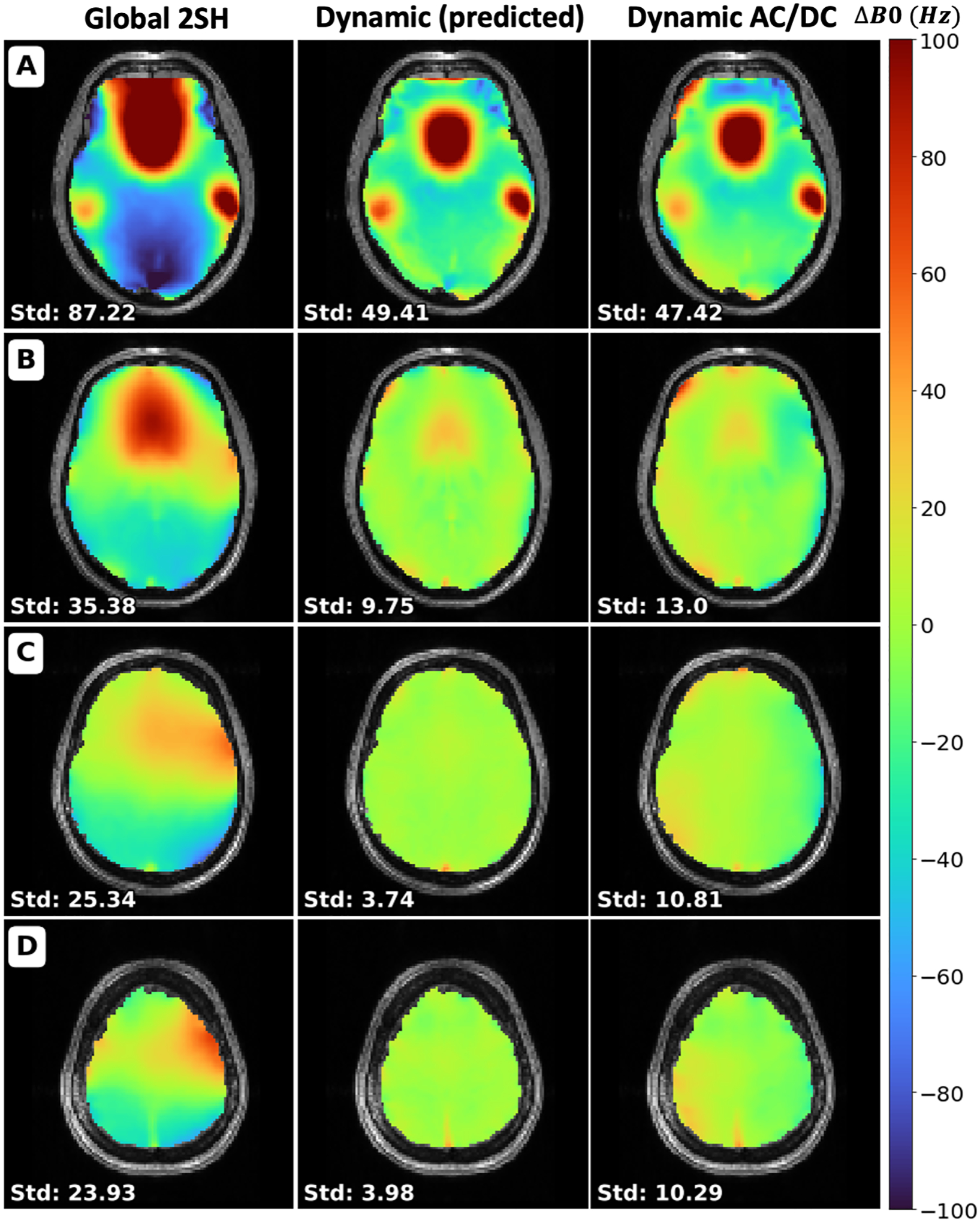
Comparison of field maps of the brain between the global 2nd order spherical harmonics optimized by the scanner (Global 2SH), the predicted dynamic shim using the AC/DC custom coil optimized by Shimming Toolbox (Dynamic (predicted)) and the acquired dynamic shim with that coil (Dynamic AC/DC). Standard deviation is shown for each slice in Hz. Slice numbers: A: 16, B: 24, C: 32, D: 40.
The dynamic shimming data are in agreement with the prediction, and show reduced inhomogeneity compared to the global shimming data. The STD of the B0 field was computed in the whole brain, resulting in 73.80 Hz for global 2SH, 39.61 Hz for dynamic (predicted) and 39.15 Hz for dynamic shimming.
These results show an improvement of the STD between the global 2SH shimming and acquired dynamic shimmed field maps in the brain of 47.0%. A plot of the STD across slices is available in Supporting Information Figure S1.
Figure 7 shows EPI slices acquired on a healthy volunteer using global shimming up to the 2nd order spherical harmonics (Global 2SH) optimized by the scanner and using slice-optimized shimming with the 31-ch AC/DC shim coil (Dynamic AC/DC) optimized by Shimming Toolbox. Two opposite phase encoding directions are shown for each experiment to visualize the geometric distortions caused by the B0 inhomogeneities (AP/PA). A brain mask outline in red was calculated using BET from an undistorted MPRAGE acquisition (MPRAGE reference). The outline is overlaid to help the comparison. Dynamic shimming showed improvements in geometric distortions when compared to global shimming. An animated GIF is included in Supporting Information Video S1 that more easily shows the distortions.
Figure 7:
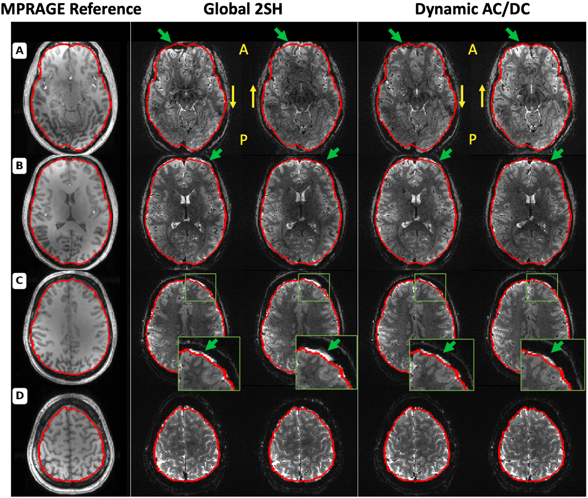
Comparison of the distortion between 2nd order SH global shimming and dynamic shimming using a 31-channel custom multi-coil shim array. Column 1 shows a reference MPRAGE acquisition where the brain outline was segmented for reference using BET and overlaid in red. Columns 2 through 5 show EPI acquisitions with the same acquisition parameters except for the shimming procedure and phase encoding direction. Columns 2 and 3 show global shimming using 2nd order spherical harmonics in the AP and PA phase encoding direction respectively. Column 4 and 5 show dynamic shimming using Shimming Toolbox and the multi-coil shim array with phase encoding direction of AP and PA respectively. Slice numbers: A: 16, B: 24, C: 32, D: 40.
Scenario 2: Breathing-induced B0 real-time dynamic shimming at 3 T
Figure 8 shows a comparison of the signal distribution within the spinal cord where the shimming ROI was defined between the 2nd order SH global shimming and real-time dynamic xyz-shimming. Average signal intensity across slices and echo times increased by 15.5% and STD decreased by 29.6%.
Figure 8:
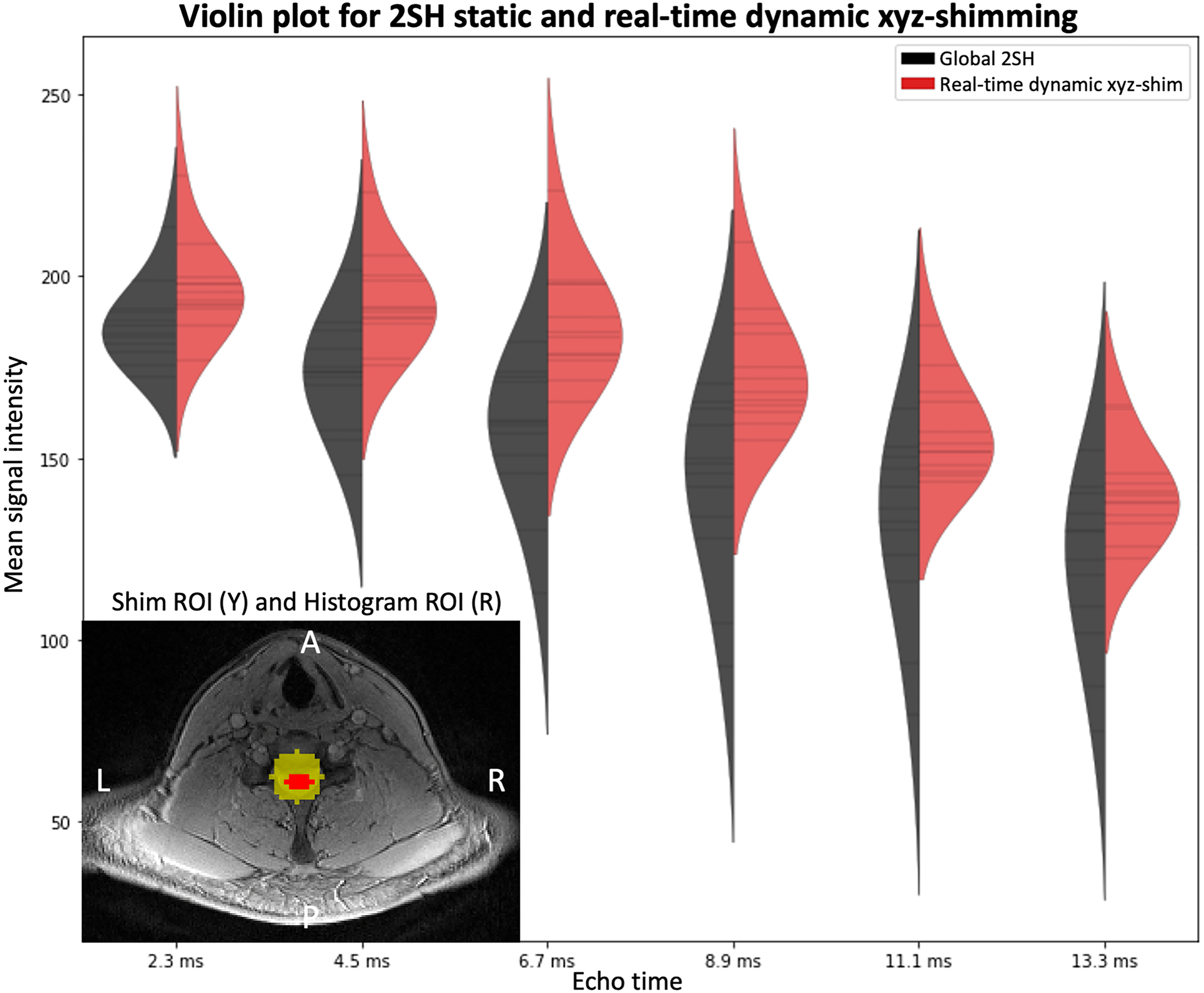
Violin plot comparing the signal distribution within the spinal cord with 2nd order global shimming (black) optimized by the scanner and with real-time dynamic xyz-shimming (red) optimized by Shimming Toolbox for multiple echo times. Mean signal intensity across slices and echo times: global/real-time: 151.54/174.99. Average standard deviation within slices: global/real-time: 19.61/13.81. An axial slice showing the location of the shim ROI for real-time shimming as well as the segmented spinal cord is shown at the bottom left of the plot.
Figure 9 shows acquired axial 2nd order SH global shimmed (Global 2SH) and real-time dynamic xyz-shimmed images of the spinal cord. One can observe more contrast between the spinal cord and surrounding tissues as well as improved signal intensity.
Figure 9:
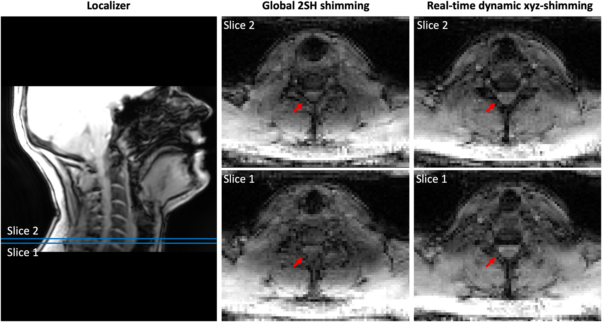
Comparison between 2nd order global shimming and real-time dynamic xyz-shimming in the spinal cord at 3 T. (Left) Localizer showing where the slices are located. (Center and Right) Slice number 1 and 2 of the same multi-echo GRE sequence acquired using 2nd order global shimming optimized by the scanner and real-time dynamic xyz-shimming optimized by Shimming Toolbox.
Scenario 3: B1 static shimming at 7 T
Figure 10 presents the normalized intensity in the spinal cord on the MP2RAGE’s UNI and GRE images, before and after B1 shimming. Spinal cords were automatically segmented on the circularly polarized (CP) mode and shimmed images. A co-registration was performed to make sure that the same anatomical regions were compared. After shimming, the coefficient of variation in the spinal cord is reduced by 10.59% on UNI images (A, B) and 39.72% on INV2 GRE images (C, D). These results show that, when compared to the CP mode, which is the default excitation mode of the coil, the shim weights optimized by Shimming Toolbox effectively reduced the inhomogeneities in the ROI on anatomical images.
Figure 10:
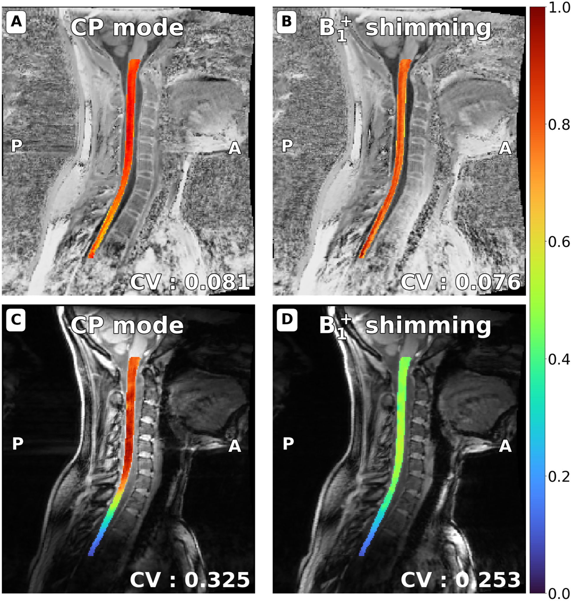
UNI (A, B) and GRE-INV2 images (C, D) spinal cord images from the MP2RAGE sequence, normalized by the maximum intensity in the spinal cord. Spinal cords were automatically segmented with SCT (and manually adjusted when required) on CP mode and shimmed images and a co-registration was performed. After shimming with Shimming Toolbox, the coefficient of variation in the spinal cord is reduced by 10.59% on UNI images (A, B) and 39.72% on GRE images (C, D).
Discussion
Shimming Toolbox is an end-to-end software package for prototyping new methods and performing B0 and B1 shimming experiments, including image format conversion, field mapping, coil calibration, masking and shimming. Below we discuss the results of the three trial experiments that were designed to validate Shimming Toolbox, as well as limitations and future improvements.
Validation experiments
The different scenarios have shown the versatility of Shimming Toolbox by homogenizing the B0 and the B1 fields. All scenarios were performed by different operators, at three different sites (3 T and 7 T) and using different sequences and applied to different anatomical parts.
The use of an AC/DC coil with dynamic shimming in the brain showed a reduction in the STD of the ΔB0 field across slices. These results are consistent with the results obtained by this coil when it was first used and published (21). Real-time dynamic xyz-shimming showed improvements in the mean and STD of the signal intensity in the spinal cord. The technique could be improved by using constant, long duration gradients rather than short, high amplitude pulses to correct the inhomogeneities.
The results of the B1 shimming functionalities applied to the spinal cord were encouraging. To improve the B1 workflow efficiency, the pulse sequence could be modified to automatically read the B1 coefficients as a text file output by Shimming Toolbox, which would save ~2 minutes over the 10 minutes it took to perform the experiment. Similar to the B0 dynamic shimming feature demonstrated, dynamically updating B1 shimming on a slice-by-slice basis (37) is part of future developments. Thanks to the modularity of Shimming Toolbox (see further discussion below), the dynamic shimming optimization application programming interface (API) can easily be applied to the B1 shimming feature.
Modularity
Shimming Toolbox is built with modularity in mind. The different B0 techniques discussed in this work were implemented to be used in a variety of scenarios. Shimming Toolbox calculates coefficients appropriately for most static experiments and supports 2D acquisitions for dynamic shimming. This allows different sequences (EPI, GRE, spin echoes), different k-space trajectories (spiral, cartesian) and different experiments (FMRI, anatomical) to be used with global and dynamic shimming while real-time shimming requires a custom sequence.
The different APIs are built so that features can conveniently be added in the future. For example, adding 3rd party unwrapping algorithms can be done via a wrapper that can call the external software package executable. Shimming techniques can make use of the already developed APIs and shimming objective functions can be added with a few lines of code.
Shimming Toolbox has been designed to be used from the command line. This design decision allows Shimming Toolbox to be integrated into other software that can access the command line. Shimming Toolbox can also be implemented in other GUIs in the future (ITKsnap) which would allow users that rely on other viewers to stay in a more familiar environment. Similarly, if proprietary MR console environments and OS distros/versions allow it, Shimming Toolbox could be integrated directly on the scanner console so that scanning sessions are more efficient and more seamlessly integrated into existing scanning workflows.
Graphical User Interface (GUI) and scripts
The GUI can be used in scanning sessions to explore the data, find the right commands and the right parameters to execute. However, the GUI is inconvenient when speed is a priority. For better efficiency and to avoid user errors, a script can be written from the simple commands used in the GUI to automate the workflow of an imaging session. It also allows multi-subject experiments to be more convenient and straightforward. Using the same script for experiments performed at different sites allows the shimming process to be consistent across the different sessions. The script also outputs quality control figures allowing the user to make on the fly assessments on the quality of the shimming. Example scripts are available on the Shimming Toolbox website.
Perspective
Other B0 shimming features not currently implemented in Shimming Toolbox would be desirable. In the context of dynamic shimming, adding a regularization of the shimming coefficients across slices could alleviate the high switching rate constraints on the gradient and shim coils. About the optimizer module, other solvers (e.g., global minimum solvers, faster solvers) could offer better solutions for specific applications. Other shimming techniques that maximize signal intensity (38) could also be implemented.
The B0 shimming pipeline relies on field maps for generating coil profiles and to generate the field to shim. By improving the field mapping pipeline, the coil profiles and field maps would be more accurate which would in turn improve shimming. Field mapping algorithms using multiple echoes could improve the reliability of those field maps. Other phase unwrappers such as UMPIRE (28) and ROMEO (29) could provide more options if an unwrapper struggles with specific field maps.
Regarding B1 shimming features, beyond workflow improvements (for example, the text file with B1 magnitude/phase shimming coefficients file being read by a sequence) and the dynamic shimming feature mentioned earlier, we would like to make Shimming Toolbox compatible with additional B1 mapping methods that could be better suited to specific anatomical regions (e.g., by minimizing breathing induced artifacts (39)).
This article focuses on imaging applications, however B0 and B1 shimming is also crucial for spectroscopy applications. Future work should include validation of Shimming Toolbox for MR spectroscopy.
Shimming Toolbox aims at supporting all the popular MRI manufacturers. Support for Siemens systems is officially available and validated. Compatibility with other platforms (e.g., Philips, GE) will require slight modifications on the DICOM to BIDS conversion (ensuring that B0 and B1 mapping sequences are properly identified as such) and on the output text file. These developments are currently underway. If using external shim coils which do not interact with the MRI’s proprietary software, Shimming Toolbox is de facto compatible regardless of the MRI manufacturer.
Open-source software development
Shimming Toolbox’s goal is to provide shimming enthusiasts with an open, modular and transparent platform. We encourage the community to contribute to this open-source software. By centralizing, standardizing and making available state-of-the-art shimming techniques, researchers will have the necessary tools to conveniently perform MR experiments, compare coils, prototype new shimming techniques and reproduce experiments published by other groups.
Conclusion
Shimming Toolbox is an open-source software package for prototyping new methods and performing B0 and B1 shimming experiments. It was validated in various shimming experiments across field strengths, imaging sites and anatomy parts. We hope that Shimming Toolbox will provide a platform on which the MRI community can collaborate, use state-of-the-art shimming techniques, contribute to new shimming techniques and make shimming research more transparent and reproducible.
Supplementary Material
Acknowledgements
We would like to thank all of the hard work from the many people that have worked on this project. A special thanks to Ryan Topfer, Ainsley Hill, Nick Guenther, Alexandru Foias, Joshua Newton, Lincoln Craven-Brightman, Johanan Idicula and Mathieu Boudreau. Funded by the Canada Research Chair in Quantitative Magnetic Resonance Imaging [950-230815], the Canadian Institute of Health Research [CIHR FDN-143263], the Canada Foundation for Innovation [32454, 34824], the Fonds de Recherche du Québec - Santé [322736], the Natural Sciences and Engineering Research Council of Canada [RGPIN-2019-07244], the Canada First Research Excellence Fund (IVADO and TransMedTech), the Courtois NeuroMod project, the Quebec BioImaging Network [5886, 35450], INSPIRED (Spinal Research, UK; Wings for Life, Austria; Craig H. Neilsen Foundation, USA), Mila - Tech Transfer Funding Program; NIH NIBIB U24 EB028984.
References
- 1.Karamat MI, Darvish-Molla S, Santos-Diaz A. Opportunities and Challenges of 7 Tesla Magnetic Resonance Imaging: A Review. Crit. Rev. Biomed. Eng 2016;44:73–89. [DOI] [PubMed] [Google Scholar]
- 2.Ibrahim TS, Hue Y-K, Tang L. Understanding and manipulating the RF fields at high field MRI. NMR Biomed. 2009;22:927–936. [DOI] [PMC free article] [PubMed] [Google Scholar]
- 3.Jezzard P, Balaban RS. Correction for geometric distortion in echo planar images from B0 field variations. Magn. Reson. Med 1995;34:65–73. [DOI] [PubMed] [Google Scholar]
- 4.Anzai Y, Lufkin RB, Jabour BA, Hanafee WN. Fat-suppression failure artifacts simulating pathology on frequency-selective fat-suppression MR images of the head and neck. AJNR Am. J. Neuroradiol 1992;13:879–884. [PMC free article] [PubMed] [Google Scholar]
- 5.van Gelderen P, de Zwart JA, Starewicz P, Hinks RS, Duyn JH. Real-time shimming to compensate for respiration-induced B0 fluctuations. Magn. Reson. Med 2007;57:362–368. [DOI] [PubMed] [Google Scholar]
- 6.Blamire AM, Rothman DL, Nixon T. Dynamic shim updating: a new approach towards optimized whole brain shimming. Magn. Reson. Med 1996;36:159–165. [DOI] [PubMed] [Google Scholar]
- 7.Koch KM, McIntyre S, Nixon TW, Rothman DL, de Graaf RA. Dynamic shim updating on the human brain. J. Magn. Reson. Resonance 2006;180:286–296 doi: 10.1016/j.jmr.2006.03.007. [DOI] [PubMed] [Google Scholar]
- 8.Topfer R, Foias A, Stikov N, Cohen-Adad J. Real-time correction of respiration-induced distortions in the human spinal cord using a 24-channel shim array. Magn. Reson. Med 2018;80:935–946. [DOI] [PubMed] [Google Scholar]
- 9.Schwerter M, Hetherington H, Moon CH, et al. Interslice current change constrained B0 shim optimization for accurate high-order dynamic shim updating with strongly reduced eddy currents. Magn. Reson. Med 2019;82:263–275. [DOI] [PMC free article] [PubMed] [Google Scholar]
- 10.Juchem C, Nixon TW, Diduch P, Rothman DL, Starewicz P, De Graaf RA. Dynamic shimming of the human brain at 7 T. Concepts Magn. Reson. Part B Magn. Reson. Eng 2010;37:116–128. [DOI] [PMC free article] [PubMed] [Google Scholar]
- 11.Pan JW, Lo K-M, Hetherington HP. Role of very high order and degree B0 shimming for spectroscopic imaging of the human brain at 7 tesla. Magn. Reson. Med 2012;68:1007–1017. [DOI] [PMC free article] [PubMed] [Google Scholar]
- 12.Juchem C, Nixon TW, McIntyre S, Rothman DL, de Graaf RA. Magnetic field modeling with a set of individual localized coils. J. Magn. Reson 2010;204:281–289. [DOI] [PMC free article] [PubMed] [Google Scholar]
- 13.Stockmann JP, Witzel T, Arango N, et al. An integrated 32ch RF-shim array coil for improved B0 shimming of the brain at 7 Tesla. In: Proc Intl Soc Magn Reson Med Vol. 26.; 2017. p. 0967. [Google Scholar]
- 14.Han H, Song AW, Truong T-K. Integrated parallel reception, excitation, and shimming (iPRES). Magn. Reson. Med 2013;70:241–247. [DOI] [PMC free article] [PubMed] [Google Scholar]
- 15.Zelaya FO, Roffmann WU, Crozier S, Teed S, Gross D, Doddrell DM. Direct visualisation of B1 inhomogeneity by flip angle dependency. Magn. Reson. Imaging 1997;15:497–504. [DOI] [PubMed] [Google Scholar]
- 16.Ibrahim TS, Lee R, Abduljalil AM, Baertlein BA, Robitaille P-ML. Dielectric resonances and B1 field inhomogeneity in UHF MRI: computational analysis and experimental findings. 10.1016/S0730-725X(01)00300-9. Published 2001. Accessed August 10, 2020 doi: 10.1016/S0730–725X(01)00300–9. [DOI] [PubMed]
- 17.Juchem. B0DETOX-B0 detoxification software for magnetic field shimming. Columbia TechVenture (CTV), License CU17326. [Google Scholar]
- 18.Nielsen J-F, Bilgic B, Stockmann JP, et al. An open toolbox for harmonized B0 shimming.
- 19.Deniz CM, Brown R, Lattanzi R, Alon L, Sodickson DK, Zhu Y. Maximum efficiency radiofrequency shimming: Theory and initial application for hip imaging at 7 tesla. Magn. Reson. Med 2013;69:1379–1388. [DOI] [PMC free article] [PubMed] [Google Scholar]
- 20.Beqiri A mriphysics/cardiac_RF_shimming: Added tracking by Zenodo.; 2017. doi: 10.5281/zenodo.231166. [DOI]
- 21.Stockmann JP, Arango NS, Witzel T, et al. A 31-channel integrated “AC/DC” B0 shim and radiofrequency receive array coil for improved 7T MRI. Magn. Reson. Med 2022;87:1074–1092. [DOI] [PMC free article] [PubMed] [Google Scholar]
- 22.McCarthy P. FSLeyes; 2019. doi: 10.5281/zenodo.3403671 [DOI]
- 23.Li X, Morgan PS, Ashburner J, Smith J, Rorden C. The first step for neuroimaging data analysis: DICOM to NIfTI conversion. J. Neurosci. Methods 2016;264:47–56. [DOI] [PubMed] [Google Scholar]
- 24.Gorgolewski KJ, Auer T, Calhoun VD, et al. The brain imaging data structure, a format for organizing and describing outputs of neuroimaging experiments. Sci Data 2016;3:160044. [DOI] [PMC free article] [PubMed] [Google Scholar]
- 25.Karakuzu A, Hollander G, Appelhof S, et al. A joint-community effort to standardize quantitative MRI data: Updates from the BIDS extension proposal. In: Proceedings of the 28th Annual Meeting of ISMRM, Sydney, Australia.; 2020. [Google Scholar]
- 26.Dcm2Bids. https://github.com/UNFmontreal/Dcm2Bids.
- 27.Jenkinson M, Fast automated, N-dimensional phase-unwrapping algorithm. Magnetic Resonance in Medicine: An Official Journal of the International Society for Magnetic Resonance in Medicine 2003;49:193–197. [DOI] [PubMed] [Google Scholar]
- 28.Robinson S, Schödl H, Trattnig S. A method for unwrapping highly wrapped multi-echo phase images at very high field: UMPIRE. Magn. Reson. Med 2014;72:80–92. [DOI] [PMC free article] [PubMed] [Google Scholar]
- 29.Dymerska B, Eckstein K, Bachrata B, et al. Phase unwrapping with a rapid opensource minimum spanning tree algorithm (ROMEO). Magn. Reson. Med 2021;85:2294–2308. [DOI] [PMC free article] [PubMed] [Google Scholar]
- 30.Smith SM. BET: Brain extraction tool. FMRIB TR00SMS2b, Oxford Centre for Functional Magnetic Resonance Imaging of the Brain), Department of Clinical Neurology, Oxford University, John Radcliffe Hospital, Headington, UK: 2000. [Google Scholar]
- 31.De Leener B, Lévy S, Dupont SM, et al. SCT: Spinal Cord Toolbox, an open-source software for processing spinal cord MRI data. Neuroimage 2016. doi: 10.1016/j.neuroimage.2016.10.009. [DOI] [PubMed] [Google Scholar]
- 32.Avdievich NI, Hoffmann J, Shajan G, et al. Evaluation of transmit efficiency and SAR for a tight fit transceiver human head phased array at 9.4 T. NMR Biomed 2017;30 doi: 10.1002/nbm.3680. [DOI] [PubMed] [Google Scholar]
- 33.Alonso-Ortiz E, Tous C, Topfer R, Cohen-Adad J. Real-Time Z-Shimming for Magnetic Resonance Imaging of the Spinal Cord. In: Proceedings of the 28th Annual Meeting of ISMRM, Sydney, Australia.; 2020. [Google Scholar]
- 34.Lopez Rios N, Topfer R, Foias A, et al. Integrated AC/DC coil and dipole Tx array for 7T MRI of the spinal cord. In: Proceedings of the 27th Annual Meeting of ISMRM, Montreal, Canada.; 2019. p. 220. [Google Scholar]
- 35.Chung S, Kim D, Breton E, Axel L. Rapid B1+ mapping using a preconditioning RF pulse with TurboFLASH readout. Magn. Reson. Med 2010;64:439–446. [DOI] [PMC free article] [PubMed] [Google Scholar]
- 36.Marques JP, Kober T, Krueger G, van der Zwaag W, Van de Moortele P-F, Gruetter R. MP2RAGE, a self bias-field corrected sequence for improved segmentation and T1-mapping at high field. Neuroimage 2010;49:1271–1281. [DOI] [PubMed] [Google Scholar]
- 37.Curtis AT, Gilbert KM, Klassen LM, Gati JS, Menon RS. Slice-by-slice B1+ shimming at 7 T. Magn. Reson. Med 2012;68:1109–1116. [DOI] [PubMed] [Google Scholar]
- 38.Kaptan M, Johanna Vannesjo S, Mildner T, et al. Automated slice-specific z-shimming for fMRI of the human spinal cord. bioRxiv 2021:2021.07.27.454049 doi: 10.1101/2021.07.27.454049. [DOI] [PMC free article] [PubMed] [Google Scholar]
- 39.Dietrich S, Aigner CS, Kolbitsch C, et al. 3D Free-breathing multichannel absolute B 1 + Mapping in the human body at 7T. Magn. Reson. Med 2021;85:2552–2567. [DOI] [PubMed] [Google Scholar]
Associated Data
This section collects any data citations, data availability statements, or supplementary materials included in this article.


