

Abstract
We evaluated excitation energy transfer (EET) coupling (J) between all pairs of chlorophylls (Chls) and pheophytins (Pheos) in the protein environment of photosystem II based on the time-dependent density functional theory with a quantum mechanical/molecular mechanics approach. In the reaction center, the EET coupling between Chls PD1 and PD2 is weaker (|J(PD1/PD2)| = 79 cm−1), irrespective of a short edge-to-edge distance of 3.6 Å (Mg-to-Mg distance of 8.1 Å), than the couplings between PD1 and the accessory ChlD1 (|J(PD1/ChlD2)| = 104 cm−1) and between PD2 and ChlD2 (|J(PD2/ChlD1)| = 101 cm−1), suggesting that PD1 and PD2 are two monomeric Chls rather than a “special pair”. There exist strongly coupled Chl pairs (|J| > ∼100 cm−1) in the CP47 and CP43 core antennas, which may be candidates for the red-shifted Chls observed in spectroscopic studies. In CP47 and CP43, Chls ligated to CP47-His26 and CP43-His56, which are located in the middle layer of the thylakoid membrane, play a role in the “hub” that mediates the EET from the lumenal to stromal layers. In the stromal layer, Chls ligated to CP47-His466, CP43-His441, and CP43-His444 mediate the EET from CP47 to ChlD2/PheoD2 and from CP43 to ChlD1/PheoD1 in the reaction center. Thus, the excitation energy from both CP47 and CP43 can always be utilized for the charge-separation reaction in the reaction center.
Significance
The excitation energy transfer (EET) coupling consists of Coulomb (Förster) and exchange (Dexter) couplings. The EET coupling was often approximated by Coulomb coupling, where the exchange coupling is neglected. However, when the edge-to-edge distance between chromophores is short (e.g., ∼4 Å in some chlorophyll pairs in photosystem II), exchange coupling cannot be neglected. In this study, we quantum-mechanically evaluated the EET coupling, taking into account exchange coupling, and identified the EET pathways from the core antennas to the reaction center in photosystem II.
Introduction
In photosynthesis, excitation energy transfer (EET) is a ubiquitous photophysical process (1,2). Photosynthetic organisms have peripheral light-harvesting (antenna) complexes to capture light energy efficiently. Light energy is absorbed by chromophores (e.g., chlorophylls (Chls)) in the light-harvesting complex and transferred to another chromophore via EET. Light energy is used in photochemical reactions in the reaction center (Fig. 1 a) (3). In EET, the electronic excitation energy is transferred from a donor molecule (D) to a nearby acceptor molecule (A) (1,2) (Fig. 1 b).
Figure 1.

Schematic illustration of EET. Schematic of (a) EET from the light-harvesting complex to the reaction center in photosynthesis, (b) EET reaction from a donor molecule (D) to an acceptor molecule (A), and its (c) Coulomb and (d) exchange mechanisms (4). A∗ and D∗ represent the excited states of A and D molecules, respectively. Black arrows indicate the motion of electrons during EET. The waves represent the Coulomb interactions between the electrons. To see this figure in color, go online.
The theory of EET was first formulated by Förster (5) in 1948 and was applied to various systems (1,2,6), including frontier biological single-molecule measurements (7). In a weak coupling scheme, the EET rate constant from a donor chromophore to an acceptor chromophore is given by the following formula based on Fermi’s golden rule (1,2,5,8,9):
| (1) |
where S is the spectral overlap integral between the donor and acceptor and J denotes the coupling (interaction) of the EET, which was originally defined by the off-diagonal matrix element between the initial and final states of the Hamiltonian. In a normal case, it can be assumed that the initial and final electronic states involved in the EET are products of the ground state of donor , the excited state of donor , the ground state of acceptor , and the excited state of acceptor , namely, the initial state and the final state . Subsequently, the EET coupling (J) can be expressed by the matrix element of the Coulomb interaction () between two electrons as and divided into two parts as follows (4):
| (2) |
with (in atomic units)
| (3) |
| (4) |
where and are the fermion creation and annihilation operators that create and annihilate electrons with spins σ and σ′ in the mutually orthogonal orbitals ϕm and ϕn, respectively. ID and IA denote the set of atomic orbital indices of the donor and acceptor molecules, respectively. core is the one-electron operator for electron-core interactions.
According to Eq. (2), EET mechanisms can be classified as either Coulomb or exchange (Dexter) mechanisms induced by JC and Jex, respectively (Fig. 1) (4). In the Coulomb mechanism, the multipole-multipole Coulomb interaction deexcites an initially excited electron on a donor molecule D and simultaneously excites an electron on an acceptor molecule A. In the exchange mechanism, excitation is transferred between D and A when an excited electron, initially belonging to D, is exchanged for a non-excited electron, initially belonging to A.
Eq. (4) indicates that the overlap of orbitals between D and A (e.g., ()) is required for Jex to have a sufficient magnitude, whereas Eq. (3) indicates that overlap is not required for JC. Therefore, when the center-to-center distance, RDA, between D and A is sufficiently large, Jex is negligibly smaller than JC owing to a small overlap. Furthermore, in this case, JC can be computed using the transition atomic charges (transition electrostatic potential (TrEsp) charges) as follows (10):
| (5) |
where qi and qS are the transition charges derived from the quantum mechanical (QM) calculations of excited states and RiS is the distance between qi and qS. Eq. (5) can be expanded by multipole-multipole Coulomb interactions (2,11). In the simplest case, the multipole-multipole interaction in Eq. (5) can be approximated by the lowest-order multipole, i.e., the dipole-dipole interaction, as (11),
| (6) |
where μD and μA are the transition dipole moments of D and A, respectively, and is the center-to-center vector from D to A. Jdipol can be recast as (1,11),
| (7) |
with an orientational factor of
| (8) |
where αDA is the angle between μD and μA and βA and βD are the angles between μD and μA, respectively, and (Fig. 2). Because the expression of Jdipol was first derived by Förster (5), the Coulomb mechanism in Eq. (3) is occasionally referred to as the Förster mechanism, whereas the exchange mechanism was first formulated by Dexter (9) (Fig. 1).
Figure 2.
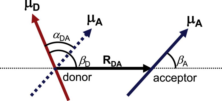
Geometric configurations of transition dipole moments of the donor (μD; red arrow) and acceptor (μA; blue solid and dotted arrows). RDA is the inter-molecular center-to-center distance between the donor and acceptor chromophores. αAD is the angle between the two transition dipole moments. βD is the angle between μD and RDA and βA is the angle between μA and RDA. To see this figure in color, go online.
The photosynthetic water-splitting enzyme, photosystem II (PSII), is a multisubunit complex in the thylakoid membranes of higher plants, algae, and cyanobacteria (12,13). The PSII core complex is composed of Chl-binding proteins, a reaction center (D1/D2/cytochrome b559 subunit), and core antennas, CP47 and CP43 (13). The reaction center has six Chl molecules, i.e., a central Chl pair of PD1/PD2, accessory Chls of ChlD1/ChlD2, peripheral Chls of ChlzD1/ChlzD2, and two pheophytins PheoD1/PheoD2. CP47 and CP43 have 16 and 13 Chls, respectively (Fig. 3) (13,14,15). Light energy is absorbed by these Chls and transferred to other Chls through EET. Finally, the energy reaches ChlD1 in the reaction center and is used for initial energy fixation by forming a charge-separated state between the Chl pair of PD1/PD2 and PheoD1 (16,17,18,19,20). The EET dynamics from CP47 and CP43 to the reaction center were observed (21,22) and calculated (23,24) together with EET couplings.
Figure 3.

Arrangement of Chls and Pheos in the PSII core complex. Chls (green) and Pheos (orange) are shown (a) parallel and (b) perpendicular to the thylakoid membrane based on PDB code 3ARC (15). The stromal, middle, and lumenal layers in CP47 and CP43 are indicated by red, cyan, and blue boxes, respectively. The reaction center contains the accessory ChlD1/ChlD2, the central Chl dimer PD1/PD2, PheoD1/PheoD2, and Mn4CaO5 cluster. Light energy captured by CP47 and CP43 is transferred to the reaction center (orange arrows) via EET and induces a charge separation between PD1/PD2 and PheoD1; this is followed by subsequent electron transfers from PheoD1 to a quinone QB (blue arrows). The electron hole on the PD1/PD2 pair is reduced by the electron transferred from the Mn4CaO5 cluster (black arrow). To see this figure in color, go online.
To analyze the EET pathway, the magnitude of EET coupling |J| should be compared with the reorganization energy λ associated with the excitation because EET coupling is also a source for the formation of excitons among the chromophores. When λ ≫ |J|, EET can be described with the rate constant expressed by Fermi’s golden rule of Eq. (1) (the so-called Förster incoherent regime) (25). In contrast, when λ ≪ |J|, EET between the chromophore pairs cannot be described by the Förster incoherent regime of Eq. (1) because the chromophores form an exciton. Therefore, it is needed to classify the treatment of chromophores into the exciton-limit and Förster-limit domains before analyzing the EET pathway (26,27).
When an exciton is formed, the absorption band of the chromophore splits into low- and high-energy bands. In the reaction center of PSII, previous studies have reported that ChlD1 has the lowest energy absorption band (19,28,29). In CP47 and CP43, spectroscopic studies (30,31,32,33,34,35,36,37,38) identified low-energy (i.e., red-shifted) trap states, which peaked in the spectra at ∼695 and ∼683 nm in CP47 (30,31,32,38) and CP43 (30,33,39), respectively. It was proposed that these peaks originated from an exciton among some Chls, and the exciton is a substance of the red-shifted trap state, i.e., “red Chl” (26,27,37,40,41). The roles of red Chls in efficient EET were proposed for PSII (42) and other photosynthetic proteins (e.g., PSI) (37,43,44,45). In the reaction center, four central Chls of PD1, PD2, ChlD1, and ChlD2 are located close to each other (Fig. 3). As the closest Chls pair among them is PD1/PD2, it was considered that PD1 and PD2 form an excitonic dimer (46,47,48). Notably, their edge-to-edge distance is short (∼4 Å) and the Mg-to-Mg distance is ∼8 Å. Alternatively, the excitonic multimer model comprising four central Chls was also proposed because the estimated EET coupling of PD1/PD2 was not sufficiently large in the same order as that of PD1/ChlD1 (∼100 cm−1) (49,50). Thus, EET coupling is a crucial factor in the context of excitons, and the values of EET couplings should be accurately estimated to investigate the charge-separation mechanism in PSII.
The expression of Jdipol is beneficial because EET coupling can be estimated based on the orientation of chromophores with the measured transition dipole moment. Therefore, EET couplings were calculated in terms of the dipole approximation (or the transition-atomic-charge approach based on Eq. (5)) described in several studies (23,40,41,48,50,51), where the Dexter term was neglected. However, J is approximated by Jdipol (JC) only when the donor and acceptor chromophores are sufficiently separated, as explained above. When they are closely located, the original expression of Eq. (2) is more approprite than Jdipol (JC). Several methodologies were developed and applied to various systems (e.g., PSII (11), CP29 (52) and light-harvesting complex II (LHCII) antenna proteins (53), PSI (54,55), the Fenna-Matthews-Olson (FMO) complex (56), solid-state tetracenes (57), and nanocrystals (10)) to calculate EET coupling beyond the dipole approximation (e.g., multipole (11) and transition-charge (10) (including the Poisson-transition-charge-from-electrostatic-potential (52,54,55,56)) approaches, where only JC is considered, and the energy-gap (53,57,58) and transition-density-fragment-interaction (59,60,61) approaches). The diabatization scheme developed by Tamura (62) is a QM method in the energy-gap approach to calculate J based on the original expression (Eq. (2)) using time-dependent density functional theory (TDDFT), which has been used in analyzing the EET and charge-separation processes in photosynthetic reaction centers, including PSII (19,20).
Although some Chl pairs in PSII are arranged with a short Mg-Mg distance (e.g., 8.1 Å for the PD1/PD2 pair) and a short edge-to-edge distance (e.g., 3.6 Å for the PD1/PD2 pair), thus far, EET couplings were calculated only in terms of Coulombic interactions, JC, i.e., the dipole approximation (23,50,51) or the transition-charge approach (37,40,52). Here, we report EET couplings calculated quantum mechanically in the presence of a PSII protein environment, considering the Dexter term and using the diabatization scheme with quantum mechanical/molecular mechanical (QM/MM) calculations.
Methods
Geometry optimization
The optimized geometry of Chls in the PSII protein environment was obtained as follows: the atomic coordinates of PSII were taken from the X-ray structure of the PSII monomer unit “A” of the PSII complexes from Thermosynechococcus vulcanus at a resolution of 1.9 Å (PDB: 3ARC) (15). Atomic partial charges of amino acids were adopted from the all-atom CHARMM22 27 parameter set (63). D1-His337 was considered to be protonated (64). The electrostatic embedding QM/MM scheme was employed, wherein the electrostatic and steric effects created by a protein environment were explicitly considered. To perform the QM/MM calculation, we used the Qsite (65) program code, employing the restricted DFT method with the B3LYP functional and LACVP∗ basis sets (LANL2DZ (double ζ quality basis set with Los Alamos effective core potential) for Mn and Ca atoms and 6-31G∗ for other atoms) (66). The QM region was defined as Chl and Pheo without the phytyl tail and the axial ligand (Table 1). The coordinates of the heavy atoms in the surrounding MM region were fixed at their original X-ray coordinates, whereas those of the H atoms in the MM region were optimized using the OPLS2005 force field. All of the atomic coordinates in the QM region were fully relaxed (i.e., not fixed) in the QM/MM calculation.
Table 1.
Ligands of Chls in the reaction center (D1 and D2), CP47, and CP43
| Layera | Chlb | Ligand | 3ARCd | 3WU2e | 2AXTf | Chlb | Ligand | 3ARCd | 3WU2e | 2AXTf |
|---|---|---|---|---|---|---|---|---|---|---|
| D2 | D1 | |||||||||
| PD2 | His197 | 605 | 402 | 354 | PD1 | His198 | 604 | 405 | 558 | |
| ChlD2 | Water | 607 | 407 | 560 | ChlD1 | water (Thr179)c | 606 | 406 | 559 | |
| PheoD2 | – | 609 | 409 | 562 | PheoD1 | – | 608 | 408 | 561 | |
| ChlzD2 | His117 | 611 | 403 | 355 | ChlzD1 | His118 | 610 | 410 | 563 | |
| CP47 | CP43 | |||||||||
| Lumen | [1] | water (Trp185-C=O, Gly186-C=O)c | 612 | 602 | 11 | – | – | – | – | – |
| [2] | His201 | 613 | 603 | 12 | – | – | – | – | – | |
| 3 | His202 | 614 | 604 | 13 | 3 | His237 | 628 | 501 | 33 | |
| 4 | His455 | 615 | 605 | 14 | 4 | His430 | 629 | 502 | 34 | |
| 5 | His100 | 616 | 606 | 15 | 5 | His118 | 630 | 503 | 35 | |
| [6] | His157 | 617 | 607 | 16 | – | – | – | – | ||
| 7 | water (Met37-C=O, Glu41)c | 618 | 608 | 17 | 7 | water (Met67, Glu71-C=O)c | 631 | 504 | 37 | |
| Middle | 13 | His26 | 624 | 614 | 26 | 13 | His56 | 637 | 510 | 46 |
| stroma | 8 | His466 | 619 | 609 | 21 | 8 | CP43-His441 | 632 | 505 | 41 |
| 9 | His216 | 620 | 610 | 22 | 9 | CP43-His251 | 633 | 506 | 42 | |
| 10 | water (Ser240, Ser241)c | 621 | 611 | 23 | 10 | water (Ser275, Tyr271-C=O)c | 634 | 507 | 43 | |
| 11 | His469 | 622 | 612 | 24 | 11 | His444 | 635 | 508 | 44 | |
| 12 | His23 | 623 | 613 | 25 | 12 | His53 | 636 | 509 | 45 | |
| 14 | His9 | 625 | 615 | 27 | 14 | Asn39 | 638 | 511 | 47 | |
| 15 | His142 | 626 | 616 | 28 | 15 | His164 | 639 | 512 | 48 | |
| 16 | His114 | 627 | 617 | 29 | 16 | His132 | 640 | 513 | 49 | |
see Fig. 3a.
Bracketed Chls are not conserved between CP43 and CP47.
These groups accept H-bond from the ligand or adjacent water molecules.
EET coupling
The excited states were calculated in the optimized geometry using the TDDFT method with 6-31G(d) basis sets and the CAM-B3LYP functional (67), as used in previous computational studies for Chls (68,69). Here, the range separation parameters μ = 0.14 (70), α = 0.19, and β = 0.46 were used. Note that the calculated values of the transition dipole moments were essentially the same as those calculated using the LC-BLYP functional (Table S2). For calculations in the protein environment, we employed a TDDFT-QM/MM/polarizable continuum model (PCM) approach (19,20,71). Here, electrostatic interactions of the protein environments were explicitly considered in the presence of bulk water with a dielectric constant of 78.39, and the solvent radius was set to 3.0 Å. The CHARMM force field (63) was used for the MM atoms. We used the QuanPol method (72) implemented in the GAMESS code (73), in which the Lennard-Jones parameters describe the interactions between QM and MM atoms.
Using the obtained electronic structures of the excited states, the QM EET coupling, Jqm, was calculated using the diabatization scheme of adiabatic electronic states (62). The protocol of diabatization used in this study is summarized as follows: 1) for the dimer composed of donor (D) and acceptor (A) molecules, we prepared a set of reference wavefunctions {ΦI} that possessed pure characteristics of the excited states, such as excitons on a single molecule (e.g., DA∗ and D∗A) and charge-transfer states (e.g., D+A− and D−A+), where D∗ and A∗ represent excited states of the D and A molecules, respectively); 2) we calculated the adiabatic electronic states {Ψk} of the dimer (DA) in the pigment-protein complexes using TDDFT-QM/MM/PCM; and 3) the diabatic wavefunction ΦI was expressed as a linear combination of the adiabatic wavefunctions {Ψk} by evaluating the overlap integrals between the reference and adiabatic wavefunctions as,
| (9) |
That is, the adiabatic states {Ψj} from the TDDFT-QM/MM/PCM calculations were considered to be basis functions for expanding the diabatic (reference) state ΦI. The diabatic coupling Jqm between ΦI and ΦJ was then evaluated as follows:
| (10) |
where H is the electronic Hamiltonian. Eq. 3 is considered for analyzing the pure Coulomb coupling, where the integrals are expanded by two-electron atomic orbital integrals (74).
The phase of wavefunctions was selected such that the sign of Jqm was the same as that of Jdipol. The EET coupling with the dipole approximation Jdipol was calculated using Eq. (6) with the transition dipole moment obtained from TDDFT calculations (Table S2), where RDA is defined as the Mg-to-Mg distance (the center-to-center distance of the Pheo rings) of the geometry-optimized Chls (Pheos). The EET coupling with the transition-charge approximation JTrEsp was calculated using Eq. (5) with the transition electrostatic charge obtained from TDDFT calculation, where Ri,s is defined based on the geometry-optimized Chls (Pheos).
Previous studies reported that the transition dipole moment calculated using TDDFT was overestimated (26,27,40). To reproduce the observed spectrum, Raszewski et al. proposed that the transition dipole moment was rescaled (26,27,40). It should be noted that the coupling calculated in this study can also be overestimated. For comparison with previous literature, the rescaled Jdipol values are provided in Table S6, although the raw values calculated quantum-mechanically without rescaling were used in this study because we primarily focused on a comparison between the couplings.
For a quantitative comparison with other studies, the J values, including the effect of the optical dielectric constant, were also calculated by applying an empirical screening factor s of (75) (Table S4).
| (11) |
where the pre-exponential factor is A = 2.68, the attenuation factor is β = 0.27, s0 = 0.54 is the asymptotic value of s at large distances, and RDA is the Mg-to-Mg distance (the center-to-center distance of the Pheo rings) in angstroms. The equation is valid when RDA > 6.6 Å.
The J values of all pairs of 35 Chls and two Pheos (Table 1) in PSII were evaluated as follows: because Jex is negligible when the overlap integrals between the donor and acceptor molecular orbitals are small, J was approximated by JTrEsp when the edge-to-edge distance d of the Chl ring (Fig. 4) was larger than 10 Å. In contrast, when the overlap integrals can be expected to be large (d < 10 Å), the QM coupling Jqm was accurately calculated using the diabatization scheme. Note that the exact Coulombic interaction JC could be sufficiently approximated by JTrEsp even in Chl pairs with short edge-to-edge distances (Table S3).
Figure 4.
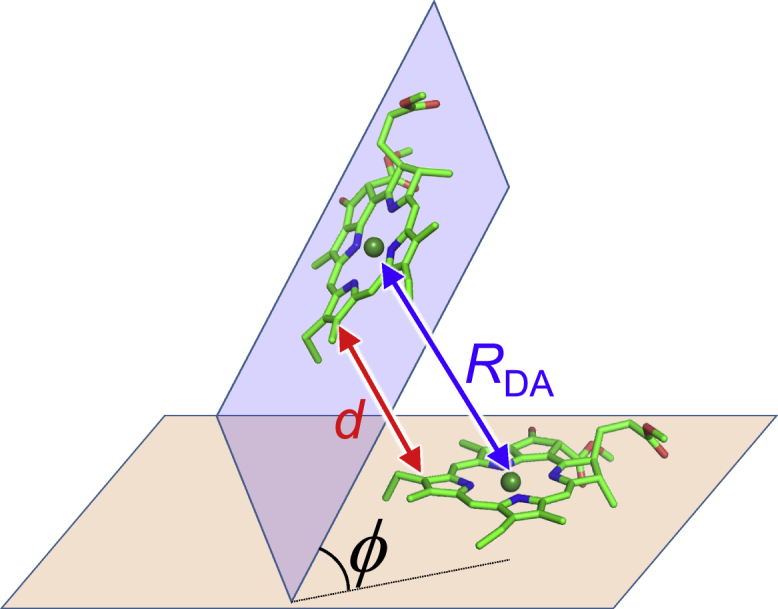
Geometric configurations of two Chls. RDA, Mg-Mg distance; d, edge-to-edge distance between chlorine rings; and ϕ, angle between the chlorine planes. To see this figure in color, go online.
Results
The J values of all pairs of 35 Chls and two Pheos in PSII were investigated (Tables 1, 2, and 3). The spatial positions and sequences of the axial ligands of all Chls are conserved between CP43 and CP47, although CP47 has three additional Chls (CP47-1, 2, and 6) (Table 1; Fig. 5; denoted with the bracket). In the reaction center, |J(PD1/PD2)| (= 79 cm−1) is smaller than |J(ChlD1/PD2)| (= 104 cm−1) and |J(ChlD2/PD1)| (= 101 cm−1), in contrast to the large |Jdipol(PD1/PD2)| (= 236 cm−1) in the dipole approximation (Fig. 6; Table 4). The large difference in J(PD1/PD2) from Jdipol indicates that the dipole approximation does not hold (Jdipol/Jqm = 3.2), especially in the PD1/PD2 pair, as reported in previous theoretical studies (56,76). In contrast, the Coulomb term JC is well approximated by JTrEsp within an error of ∼2% (Table 4). This result indicates that the TrEsp approximation (JTrEsp) is appropriate provided that Jex is sufficiently small (Table S3).
Table 2.
EET coupling J between Chls in the reaction center and CP47 (cm−1)
 |
Values for Jqm are shown in bold due to the short edge-to-edge distance (d < 10 Å). The bracketed Chls are not conserved between CP43 and CP47. Values are colored in red, orange, yellow, green, and blue for |J| > 150, 125, 100, 50, and 10 cm−1, respectively. See Table S4 for the case in which the distance-dependent dielectric constant is considered.
Table 3.
EET coupling J between Chls in the reaction center and CP43 (cm−1)
 |
Values for Jqm are shown in bold due to the short edge-to-edge distance (d < 10 Å). Values are colored in red, orange, yellow, and blue for |J| > 150, 125, 100, 50, and 10 cm−1, respectively.
Figure 5.

Sequence alignment of CP43 and CP47 from T. vulcanus with the axial ligands of Chls, His (yellow) and Asn (green), hydrogen-bond (H-bond) acceptor of the ligand water cluster of Chl (cyan), and transmembrane helix regions (gray), obtained using Clustal (77). The boxed numbers indicate Chls defined in Table 1. Bracketed Chls are not conserved between CP43 and CP47. To see this figure in color, go online.
Figure 6.

EET coupling network (|J| >10 cm−1). View from the field (a) parallel and (b) perpendicular to the membrane. Color and width of the lines indicate the magnitude of J. The Chl number corresponds to that in Table 1 (the blue bracketed number indicates Chl existing only in CP47). The boxed picture shows EET coupling, Jdipol, calculated by the dipole approximation. To see this figure in color, go online.
Table 4.
Calculated couplings among the four central Chls and two Pheos in the reaction center
| Chl pair | RDA (Å) | da (Å) | κb | ϕc (◦) | Jqm (cm−1) | Jexd (cm−1) | JC (cm−1) | JTrEsp (cm−1) | JTrEsp/JC | Jdipol (cm−1) | Jdipol/Jqm | |
|---|---|---|---|---|---|---|---|---|---|---|---|---|
| PD1 | PD2 | 8.1 | 3.6 | 0.92 | 1.2 | 79.1 | −6.0 | 85.0 | 86.6 | 1.02 | −235.7 | 3.20 |
| PD1 | ChlD1 | 10.4 | 4.5 | −0.22 | 65.4 | −58.0 | 4.9 | −62.9 | −63.1 | 1.00 | −29.7 | 0.64 |
| PD1 | ChlD2 | 12.2 | 5.1 | −1.59 | 72.3 | −104.2 | −11.3 | −92.9 | −92.5 | 1.00 | 132.4 | 1.19 |
| PD1 | PheoD1 | 15.4 | 7.8 | −0.24 | 62.5 | −7.4 | 1.9 | −9.3 | −9.4 | 1.01 | −8.2 | 1.12 |
| PD2 | ChlD1 | 12.1 | 5.2 | −1.54 | 64.5 | −101.4 | −10.4 | −91.0 | −91.7 | 1.01 | 131.5 | 1.26 |
| PD2 | ChlD2 | 10.5 | 5.0 | −0.14 | 73.6 | −48.4 | 5.4 | −53.7 | −54.2 | 1.01 | −16.8 | 0.33 |
| PD2 | PheoD2 | 15.1 | 7.5 | −0.24 | 66.0 | −5.8 | 0.3 | 33.1 | −7.5 | 1.00 | −8.7 | 1.49 |
| PheoD1 | ChlD1 | 10.5 | 4.7 | 1.02 | 62.1 | 100.1 | 11.0 | 89.1 | 88.5 | 0.99 | 126.6 | 1.27 |
| PheoD2 | ChlD2 | 10.6 | 5.0 | 0.92 | 62.3 | 71.3 | −0.8 | 72.0 | 71.4 | 0.99 | 103.3 | 1.45 |
The calculated J values showed the same trend between the Chl pairs in CP43 (Table 2) and CP47 (Table 3) because of the similar sequential and spatial arrangement of Chls (Fig. 6). Chls in CP47 and CP43 can be classified into stromal-, middle-, and lumenal-layer Chls (Fig. 3 a; Table 1) (40). In both CP47 and CP43, intricate network of EET coupling are formed within the stromal and lumenal layers (Fig. 6; red and blue arrows in Fig. 7) and between the middle-layer Chls (CP47-13 and CP43-13) and both the stromal and lumenal Chls (light-brown arrow in Fig. 7) compared with the EET coupling of Chl pairs between the stromal and lumenal layers (purple arrow in Fig. 7). Furthermore, several Chl pairs have large EET couplings (|J| > 100 cm−1) in CP47 and CP43 (Figs. 6 and 7). In contrast, between the reaction center and the core antennas (CP47 and CP43), only a few Chl/Chl and Chl/Pheo pairs are coupled with small J values (|J| ∼10–20 cm−1), and other pairs have no couplings (Fig. 6; red and black arrows in Fig. 7). Note that the EET coupling of all Chl pairs between CP47 and CP43 could be approximated by Jdipol owing to their long distances and small magnitudes (<∼1 cm−1) (Tables S5 and S7; Fig. S1).
Figure 7.

Distribution of the EET interaction J between Chls in the lumenal layer (blue arrow), Chls in the stromal layer (red arrow), middle-layer Chl (CP47-13/CP43-13) and lumenal or stromal Chls (light-brown arrow), lumenal Chls and stromal Chls (purple arrow), and core-antenna Chls and reaction-center Chls (black arrow). (a) Conceptual illustration of the classification of Chl pairs. (b) Distributions in CP47. (c) Distributions in CP43. Values greater than the vertical scale are shown in parentheses. To see this figure in color, go online.
Discussion
Nature of the PD1/PD2 pair
In the PD1/PD2 pair, the dipole approximation does not hold (Jdipol/Jqm = 3.2) (Table 4). This can be explained by the following reasons: the PD1/PD2 Chls are located at a short Mg-Mg distance of 8.1 Å with a short edge-to-edge distance of 3.6 Å (Table 4). In addition, they are arranged in a parallel manner (angle between the chlorine planes, ϕ = 1°) (Table 4; Fig. 8). In this case, the delocalization effect of the transition atomic charges of the Chls cannot be neglected. In contrast, both ChlD1/PD2 and ChlD2/PD1 Chls are arranged in a non-parallel manner (ϕ = ∼60°) (Table 4; Fig. 8), and the transition atomic charges of Chls can be approximated by the transition dipole. Thus, their couplings have similar values to those in the dipole approximation (Jdipol/Jqm, ∼1.2–1.3). The PD1/PD2 pair was considered to form excitons as a “special pair” (46,47,48) or an excitonic multimer (49,50) owing to their short distance and analogy with the special pair PL/PM in the bacterial reaction center (16), as the EET coupling of PD1/PD2 was estimated to be large (∼150–200 cm−1) in theoretical studies (37,48,50). However, the calculations in the present study show that the PD1/PD2 pair has a weaker coupling (79.1 cm−1) than the ChlD1/PD2 (−104.2 cm−1) and ChlD2/PD1 pairs (−101.4 cm−1). Furthermore, the site energy of PD1 is 16 meV (130 cm−1) smaller than that of PD2; i.e., PD1 and PD2 are not degenerated (Table S1). This finding differs from results in previous theoretical studies, which reported that PD1 and PD2 were (almost) degenerated. This may originate from a difference in the treatment of the protein environment between our QM/MM calculations and methods used in the previous studies. In our QM/MM calculations, the protein structure was taken into account at the atomic level, whereas it was not in model Hamiltonian calculations (e.g., Novoderezhkin et al. (78)). In our QM/MM calculations, the steric effect of Chl geometries from the protein environment was taken into account, whereas it was not in Poisson-Boltzmann electrostatic calculations (e.g., Müh et al. (79)). Thus, PD1 and PD2 are two monomeric Chls rather than a special pair, or a part of the excitonic multimer, as pointed out by Tamura et al. (20).
Figure 8.

Arrangement of PD1, PD2, and ChlD2. Chlorine planes of PD1 and PD2 are arranged in a parallel manner (angle between the chlorine planes, ϕ = ∼0°), whereas those of PD1 and ChlD2 are arranged in a non-parallel manner (ϕ = ∼60°). To see this figure in color, go online.
Intriguingly, among all the Chl pairs in the reaction center, only the PD1/PD2 pair has a large contribution (21%) of the charge-transfer excited state to the adiabatic excitonic state of the Chl dimer (Table S8). The superexchange excitonic coupling of the PD1/PD2 pair involving the charge-transfer excited states (80) was calculated. The superexchange excitonic coupling from D to A states JSX(D→A) is given by,
| (12) |
with elements of the Hamiltonian matrix given in Table S9: Ex is the diagonal element of state x and Jyz is the off-diagonal element between states y and z. The summation of M takes over the intermediate M states, which correspond to the charge-transfer excited states of PD1−PD2+ and PD1+PD2− in this case. The calculated JSX(PD1∗PD2→PD1PD2∗) and JSX(PD1PD2∗→PD1∗PD2) are −6.4 cm−1 and −7.4 cm−1, respectively, whose magnitudes are smaller than the direct coupling of Jqm (79.1 cm−1; Table 4). Therefore, our conclusion that the PD1/PD2 pair is monomeric does not change, even when the effect of JSX is considered. The J values of the ChlD1/PD1 and ChlD2/PD2 pairs are smaller than those of the ChlD1/PD2 and ChlD2/PD1 pairs because of their small orientational factor (|κ| < ∼0.2) (Table 4).
Candidates of red chlorophyll
When the EET coupling is sufficiently stronger than the homogeneous energy broadening D (induced by the interaction between electrons in the Chl and the protein environment), the coupled Chls form an exciton (48). Here, D can be estimated by
| (13) |
when the thermal energy kBT is sufficiently high compared with the typical quantum energy of the slow vibrational mode of the solvent molecules and λ represents the reorganization energy associated with the excitation (70). According to Eq. (13), D is estimated to be ∼60 cm−1 at 77 K from the typical reorganization energy (λ = ∼30 cm−1) estimated for Chla in PS II (48).
The calculated J values show that the Chl pairs of 12/14, 4/7, and 8/10 in both CP47 and CP43, and CP47-2/3, CP47-3/[6], CP47-5/[6], and CP47-13/14 have large EET couplings (>∼100 cm−1) (Tables 2 and 3; Fig. 6). These Chl pairs can form excitons with a low absorption energy at ∼77 K because the magnitude of their couplings |J| is sufficiently larger than that of D and λ. Thus, they are the most likely candidates for red Chl, which absorbs a significantly longer wavelength than other Chls. In contrast to the PD1/PD2 pair in the reaction center, the contributions of the charge-transfer excited state to the adiabatic excitonic state of the dimer were negligibly small (<1%) in those Chl pairs (Table S8). A part of the strongly coupled Chls in CP43, i.e., CP43-7 (26,40,52), 10 (26,37,40), and 12 (26,37,40), is consistent with the proposed red Chls in previous studies. In contrast, no Chl was found in CP47, consistent with the proposed red Chl, where CP47-16 was proposed to emit a fluorescence of 695 nm (37) (Fig. 9). Because CP47-8 and -13 have small site energies (2.092–2.094 eV) (Table S1), the CP47-8/10 and -13/14 pairs are the most likely candidates for red Chls.
Figure 9.

Strongly coupled Chl pairs that are candidates of red Chls. The proposed red Chls (CP43-7 (26,40,52), 10 (26,37,40), and 12 (26,37,40), and CP47-16 (37)) are colored in red. To see this figure in color, go online.
Mechanism of charge separation
In EET couplings of the four central Chls (i.e., PD1, PD2, ChlD1, and ChlD2) and two Pheos in the reaction center with Chls in CP47 and CP43, only the ChlD2/CP47-8, PheoD2/CP47-8, ChlD1/CP43-8, PheoD1/CP43-8, and PheoD1/CP43-11 pairs have sufficiently large couplings (|J| = ∼10–15 cm−1). Thus, the excitation energy is transferred through pathways from CP47-8 to ChlD2 or PheoD1, from CP43-8 to ChlD1 or PheoD1, and from CP43-11 to PheoD1. Because the PheoD1/ChlD1 and PheoD2/ChlD2 couplings are sufficiently large (|J| = ∼70–100 cm−1), the excitation energies on PheoD1 and PheoD2 can be easily transferred to ChlD1 and ChlD2, respectively. The excited ChlD1 can induce a charge-separation reaction between PheoD1 and the PD1/PD2 pair (20,29). In contrast, the excitation energy of ChlD2 cannot cause a charge-separation reaction directly (20) but can be transferred through both a “direct” pathway from ChlD2 to ChlD1 (|J(ChlD2/ChlD1)| = 14 cm−1) and an “indirect” pathway from ChlD2 via PD1 to ChlD1 (|J(ChlD2/PD1)| = 104 cm−1 and |J(PD1/ChlD1)| = 58 cm−1). Although the excitation energy of PD2 is higher than that of ChlD2 (Table S1), the large |J(ChlD2/PD1)| (=104 cm−1) allows the excitation energy to be transferred to ChlD1 by overcoming the energy barrier of PD2, as reported in a previous theoretical study (20). Thus, the excitation energy from both CP47 and CP43 can be used for the formation of a charge-separated state in the reaction center (Fig. 10).
Figure 10.

EET pathways and the charge-separation reaction in PSII. View from the field (a) parallel and (b) perpendicular to the membrane. The middle-layer Chls of CP47-13 and CP43-13 connect network between the lumenal and stromal layers. The excitation energy from CP47-8 and CP43-8/11 in the stromal layer reaches the reaction center (red arrows). Because ChlD1/PD2 and ChlD2/PD1 are strongly coupled (yellow line) compared with the PD1/PD2 pair (green line), the excitation energy on ChlD2 can be transferred to ChlD1 via PD1 (black arrow); thus, it is used for the charge-separation reaction on ChlD1(20) (blue arrows). To see this figure in color, go online.
EET between the lumenal and stromal layers
Light energy can be captured by Chls in both stromal and lumenal layers in CP47 and CP43. The excitation energy also reaches CP47 and CP43 from a peripheral antenna, LHCII. Based on the cryoelectron-microscopy structures of the PSII/LHCII supercomplex, the acceptor Chls in the EET from LHCII were identified (e.g., CP47-15, CP47-[6], CP43-15, and CP47-16 (51)) in both stromal and lumenal layers. As the excitation energy is transferred to the reaction center through stromal Chls of CP47-8, CP43-8, and CP43-11, as discussed above, the energy captured in the lumenal layer must be transferred to the stromal layer. However, the direct EET between the stromal and lumenal Chls appears to be inefficient because the Chl pairs between them are weakly coupled (Tables 2 and 3; purple arrow in Fig. 7). In contrast, the middle-layer Chls of CP47-13 and CP43-13 exhibit sufficient interactions (|J| > ∼40 cm−1) with Chls in the lumenal and stromal layers and, thus, have several links with Chls in both the stromal and lumenal layers (Tables 2 and 3; light-brown arrow in Fig. 7). Therefore, middle-layer Chls are essential to transfer energy from the lumenal layer to the stromal layer. Here, middle-layer Chls play a role in the “hub” that connects the network between the stromal and lumenal layers (Fig. 10 a).
Comparison with other photosynthetic complexes
Other photosynthetic proteins (e.g., PSI, LHCI, and LHCII) also possess multiple Chls. Most of these Chls are localized in the lumenal and stromal layers, similar to CP47 and CP43. The localization is probably because polar substitution groups in Chls (e.g., carbonyl and methyl ester groups) make it difficult for them to locate in the hydrophobic middle layer of lipid bilayers. The PSII-LHCII (51) and PSI-LHCI (81) structures showed that these Chls in the lumenal and stromal layers are arranged at a short distance (Mg-Mg distance of ∼10 Å). Therefore, they may strongly couple to each other within the layer, forming an intricate EET network. As the excitation energy can be captured or received from the adjacent antenna systems by the Chls in both the lumenal and stromal layers, the excitation energy has to move between the layers. The protein structures shows that a few Chls are also located in the middle layer (e.g., Chls at His-A734 and His-B718 in PSI from Synechococcus elongatus (82) and His68 in LHCII from pea (83)). From the analogy of CP47 and CP43, these middle-layer Chls may play the role of a hub that connects the lumen side to the stroma side in other photosynthetic proteins.
When the edge-to-edge distance d is shorter than 10 Å, the quantum chemical calculation of the EET coupling was applied in the present study. In PSII, this situation holds true only for the intra-subunit Chl pairs. Therefore, the inter-subunit EET (i.e., between the reaction center and CP47, the reaction center and CP43, and CP47 and CP43) can be estimated based on the EET coupling via the Coulomb-term approximation, although the intra-subunit EET cannot. As the Chls are arranged at a short distance (Mg-Mg distance of ∼10 Å) in other photosystems (e.g., PSI, LHCI, and LHCII), the previous calculations of intra-subunit EET based on the approximated EET coupling (e.g., for the FMO complex(84)) may be revisited with EET couplings calculated quantum-mechanically.
Conclusions
In this study, we analyzed EET couplings quantum-mechanically in the presence of the PSII protein environment, considering the Dexter term and using the QM/MM diabatization scheme. In the reaction center, |J(PD1/PD2)| (= 75 cm−1) is smaller than |J(ChlD1/PD2)| (= 110 cm−1) and |J(ChlD2/PD1)| (= 104 cm−1) (Table 4; Fig. 6). Because the PD1/PD2 pair has a weaker coupling than the ChlD1/PD2 and ChlD2/PD1 pairs, PD1 and PD2 are two monomeric Chls rather than a special pair, or a part of the excitonic multimer.
Light energy captured by Chls in CP43 and CP47 can be transferred within stromal and lumenal layers through the intricate network of EET coupling (Fig. 10). The energy may be trapped by the red-shifted Chl state formed as an exciton delocalized over strongly coupled Chls (Chl pairs of 12/14, 4/7, and 8/10 in both CP47 and CP43, and 2/3, 3/[6], 5/[6], and 13/14 in CP47) (Fig. 9), especially at low temperature. The excitation energy can be transferred between the stromal and lumenal layers through the middle-layer Chls (CP47-13 and CP43-13), which play a role in the hub that connects the network between the layers (Fig. 10 a). Finally, the excitation energy in the core antennas is transferred from CP47-8 and -11 to ChlD2/PheoD2 or CP43-8 to ChlD1/PheoD1. After the energy reaches PheoD2 or ChlD2 in the D2 subunit from CP43-8, it is transferred to ChlD1 via PD1 owing to the large |J(PheoD2/ChlD2)|, |J(ChlD2/PD1)|, and |J(PheoD2/PD1)| (>∼70 cm−1) (20). Thus, the excitation energy from both CP47 and CP43 can always be utilized for the formation of a charge-separated state in the reaction center (Fig. 10).
Author contributions
H.I. and K.S. designed research. K.S. and K.M performed research. H.T. contributed analytic tools. All authors participated in analyzing data and writing the manuscript.
Acknowledgments
This research was supported by JST CREST (JPMJCR1656 to H.I), JSPS KAKENHI (JP18H01937, JP18H05155, JP20H03217, and JP20H05090 to H.I., and JP18H01186 to K.S.), and Interdisciplinary Computational Science Program in CCS, University of Tsukuba.
Declaration of interests
The authors declare no competing interests.
Editor: Judy Kim.
Footnotes
Supporting material can be found online at https://doi.org/10.1016/j.bpj.2023.01.002.
Contributor Information
Keisuke Saito, Email: ksaito@appchem.t.u-tokyo.ac.jp.
Hiroyuki Tamura, Email: tamura@protein.rcast.u-tokyo.ac.jp.
Hiroshi Ishikita, Email: hiro@appchem.t.u-tokyo.ac.jp.
Supporting material
References
- 1.Scholes G.D. Long-range resonance energy transfer in molecular systems. Annu. Rev. Phys. Chem. 2003;54:57–87. doi: 10.1146/annurev.physchem.54.011002.103746. [DOI] [PubMed] [Google Scholar]
- 2.You Z., Hsu C. Theory and calculation for the electronic coupling in excitation energy transfer. Int. J. Quantum Chem. 2014;114:102–115. [Google Scholar]
- 3.Yokono M., Akimoto S. Energy transfer and distribution in photosystem super/megacomplexes of plants. Curr. Opin. Biotechnol. 2018;54:50–56. doi: 10.1016/j.copbio.2018.01.001. [DOI] [PubMed] [Google Scholar]
- 4.Damjanović A., Ritz T., Schulten K. Energy transfer between carotenoids and bacteriochlorophylls in light-harvesting complex II of purple bacteria. Phys. Rev. E. 1999;59:3293–3311. [Google Scholar]
- 5.Förster T. Zwischenmolekulare Energiewanderung und Fluoreszenz. Ann. Phys. 1948;437:55–75. [Google Scholar]
- 6.Selvin P.R. The renaissance of fluorescence resonance energy transfer. Nat. Struct. Biol. 2000;7:730–734. doi: 10.1038/78948. [DOI] [PubMed] [Google Scholar]
- 7.Li C.C., Li Y., et al. Zhang C.Y. Single-molecule fluorescence resonance energy transfer and its biomedical applications. TrAC Trends Anal. Chem. 2020;122 [Google Scholar]
- 8.Förster T. In: Modern Quantum Chemistry, Istanbul Lectures: Part III: Action of Light and Organic Crystals. Sinamoglu O., editor. Academic Press; 1965. Delocalized excitation and excitation transfer. [Google Scholar]
- 9.Dexter D.L. A theory of sensitized luminescence in solids. J. Chem. Phys. 1953;21:836–850. [Google Scholar]
- 10.Chang J.C. Monopole effects on electronic excitation interactions between large molecules. I. Application to energy transfer in chlorophylls. J. Chem. Phys. 1999;67:3901–3909. [Google Scholar]
- 11.Baer R., Rabani E. Theory of resonance energy transfer involving nanocrystals: the role of high multipoles. J. Chem. Phys. 2008;128:184710. doi: 10.1063/1.2913247. [DOI] [PubMed] [Google Scholar]
- 12.Cardona T., Rutherford A.W. Evolution of photochemical reaction centres: more twists? Trends Plant Sci. 2019;24:1008–1021. doi: 10.1016/j.tplants.2019.06.016. [DOI] [PubMed] [Google Scholar]
- 13.Shen J.R. The structure of photosystem II and the mechanism of water oxidation in photosynthesis. Annu. Rev. Plant Biol. 2015;66:23–48. doi: 10.1146/annurev-arplant-050312-120129. [DOI] [PubMed] [Google Scholar]
- 14.Loll B., Kern J., et al. Biesiadka J. Towards complete cofactor arrangement in the 3.0 Å resolution structure of photosystem II. Nature. 2005;438:1040–1044. doi: 10.1038/nature04224. [DOI] [PubMed] [Google Scholar]
- 15.Umena Y., Kawakami K., Kamiya N., et al. Crystal structure of oxygen-evolving photosystem II at a resolution of 1.9 Å. Nature. 2011;473:55–60. doi: 10.1038/nature09913. [DOI] [PubMed] [Google Scholar]
- 16.Cardona T., Sedoud A., et al. Rutherford A.W. Charge separation in photosystem II: a comparative and evolutionary overview. Biochim. Biophys. Acta. 2012;1817:26–43. doi: 10.1016/j.bbabio.2011.07.012. [DOI] [PubMed] [Google Scholar]
- 17.Dekker J.P., van Grondelle R. Primary charge separation in photosystem II. Photosynth. Res. 2000;63:195–208. doi: 10.1023/A:1006468024245. [DOI] [PubMed] [Google Scholar]
- 18.Prokhorenko V.I., Holzwarth A.R. Primary process and structure of the photosystem II reaction center: a photon echo study. J. Phys. Chem. B. 2000;104:11563–11578. [Google Scholar]
- 19.Tamura H., Saito K., Ishikita H. Acquirement of water-splitting ability and alteration of the charge-separation mechanism in photosynthetic reaction centers. Proc. Natl. Acad. Sci. USA. 2020;117:16373–16382. doi: 10.1073/pnas.2000895117. [DOI] [PMC free article] [PubMed] [Google Scholar]
- 20.Tamura H., Saito K., Ishikita H. The origin of unidirectional charge separation in photosynthetic reaction centers: nonadiabatic quantum dynamics of exciton and charge in pigment-protein complexes. Chem. Sci. 2021;12:8131–8140. doi: 10.1039/d1sc01497h. [DOI] [PMC free article] [PubMed] [Google Scholar]
- 21.van Amerongen H., Croce R. Light harvesting in photosystem II. Photosynth. Res. 2013;116:251–263. doi: 10.1007/s11120-013-9824-3. [DOI] [PMC free article] [PubMed] [Google Scholar]
- 22.Andrizhiyevskaya E.G., Frolov D., et al. Dekker J.P. On the role of the CP47 core antenna in the energy transfer and trapping dynamics of photosystem II. Phys. Chem. Chem. Phys. 2004;6:4810–4819. [Google Scholar]
- 23.Saito K., Kikuchi T., et al. Sumi H. A single chlorophyll in each of the core antennas CP43 and CP47 transferring excitation energies to the reaction center in Photosystem II of photosynthesis. J. Photochem. Photobiol. Chem. 2006;178:271–280. [Google Scholar]
- 24.Pawlowicz N.P., Groot M.L., et al. van Grondelle R. Charge separation and energy transfer in the photosystem II core complex studied by femtosecond midinfrared spectroscopy. Biophys. J. 2007;93:2732–2742. doi: 10.1529/biophysj.107.105452. [DOI] [PMC free article] [PubMed] [Google Scholar]
- 25.Ishizaki A., Fleming G.R. Unified treatment of quantum coherent and incoherent hopping dynamics in electronic energy transfer: reduced hierarchy equation approach. J. Chem. Phys. 2009;130:234111. doi: 10.1063/1.3155372. [DOI] [PubMed] [Google Scholar]
- 26.Raszewski G., Renger T. Light harvesting in photosystem II core complexes is limited by the transfer to the trap: can the core complex turn into a photoprotective mode? J. Am. Chem. Soc. 2008;130:4431–4446. doi: 10.1021/ja7099826. [DOI] [PubMed] [Google Scholar]
- 27.Müh F., Madjet M.E.A., Renger T. Structure-based identification of energy sinks in plant light-harvesting complex II. J. Phys. Chem. B. 2010;114:13517–13535. doi: 10.1021/jp106323e. [DOI] [PubMed] [Google Scholar]
- 28.Saito K., Mitsuhashi K., Ishikita H. Dependence of the chlorophyll wavelength on the orientation of a charged group: why does the accessory chlorophyll have a low site energy in photosystem II? J. Photochem. Photobiol. Chem. 2020;402 [Google Scholar]
- 29.Sirohiwal A., Neese F., Pantazis D.A. Protein matrix control of reaction center excitation in photosystem II. J. Am. Chem. Soc. 2020;142:18174–18190. doi: 10.1021/jacs.0c08526. [DOI] [PMC free article] [PubMed] [Google Scholar]
- 30.Vandorssen R.J., Plijter J.J., et al. Vangorkom H.J. Spectroscopic properties of chloroplast grana membranes and of the core of photosystem-II. Biochim. Biophys. Acta Bioenerg. 1987;890:134–143. [Google Scholar]
- 31.van Dorssen R.J., Breton J., et al. Amesz J. Spectroscopic properties of the reaction center and of the 47 kDa chlorophyll protein of photosystem II. Biochim. Biophys. Acta Bioenerg. 1987;893:267–274. [Google Scholar]
- 32.Dekker J.P., Hassoldt A., van Grondelle R., et al. Photosynthesis: From Light to Biosphere. Vol I. 1995. On the nature of the F695 and F685 emission of photosystem II; pp. 53–56. [Google Scholar]
- 33.Jankowiak R., Zazubovich V., Small G.J., et al. The CP43 core antenna complex of photosystem II possesses two quasi-degenerate and weakly coupled Qy-trap states. J. Phys. Chem. B. 2000;104:11805–11815. [Google Scholar]
- 34.De Weerd F.L., Palacios M.A., et al. van Grondelle R. Identifying the lowest electronic states of the chlorophylls in the CP47 core antenna protein of photosystem II. Biochemistry. 2002;41:15224–15233. doi: 10.1021/bi0261948. [DOI] [PubMed] [Google Scholar]
- 35.Andrizhiyevskaya E.G., Chojnicka A., et al. Dekker J.P. Origin of the F685 and F695 fluorescence in photosystem II. Photosynth. Res. 2005;84:173–180. doi: 10.1007/s11120-005-0478-7. [DOI] [PubMed] [Google Scholar]
- 36.Komura M., Shibata Y., Itoh S. A new fluorescence band F689 in photosystem II revealed by picosecond analysis at 4-77 K: function of two terminal energy sinks F689 and F695 in PSII. Biochim. Biophys. Acta. 2006;1757:1657–1668. doi: 10.1016/j.bbabio.2006.09.007. [DOI] [PubMed] [Google Scholar]
- 37.Shibata Y., Nishi S., et al. Renger T. Photosystem II does not possess a simple excitation energy funnel: time-resolved fluorescence spectroscopy meets theory. J. Am. Chem. Soc. 2013;135:6903–6914. doi: 10.1021/ja312586p. [DOI] [PMC free article] [PubMed] [Google Scholar]
- 38.Neupane B., Dang N.C., et al. Jankowiak R. Insight into the electronic structure of the CP47 antenna protein complex of photosystem II: hole burning and fluorescence study. J. Am. Chem. Soc. 2010;132:4214–4229. doi: 10.1021/ja908510w. [DOI] [PubMed] [Google Scholar]
- 39.Hughes J.L., Picorel R., et al. Krausz E. Photophysical behavior and assignment of the low-energy chlorophyll states in the CP43 proximal antenna protein of higher plant photosystem II. Biochemistry. 2006;45:12345–12357. doi: 10.1021/bi0614683. [DOI] [PubMed] [Google Scholar]
- 40.Müh F., Madjet M.E.A., Renger T. Structure-based simulation of linear optical spectra of the CP43 core antenna of photosystem II. Photosynth. Res. 2012;111:87–101. doi: 10.1007/s11120-011-9675-8. [DOI] [PubMed] [Google Scholar]
- 41.Dang N.C., Zazubovich V., et al. Jankowiak R. The CP43 proximal antenna complex of higher plant photosystem II revisited: modeling and hole burning study. I. J. Phys. Chem. B. 2008;112:9921–9933. doi: 10.1021/jp801373c. [DOI] [PubMed] [Google Scholar]
- 42.Kosugi M., Ozawa S.I., Koike H., et al. Red-shifted chlorophyll a bands allow uphill energy transfer to photosystem II reaction centers in an aerial green alga, Prasiola crispa, harvested in Antarctica. Biochim. Biophys. Acta Bioenerg. 2020;1861:148139. doi: 10.1016/j.bbabio.2019.148139. [DOI] [PubMed] [Google Scholar]
- 43.Hayes J.M., Matsuzaki S., Small G.J., et al. Red chlorophyll a antenna states of photosystem I of the cyanobacterium Synechocystis sp PCC 6803. J. Phys. Chem. B. 2000;104:5625–5633. [Google Scholar]
- 44.Lee Y., Gorka M., et al. Anna J.M. Ultrafast energy transfer involving the red chlorophylls of cyanobacterial photosystem I probed through two-dimensional electronic spectroscopy. J. Am. Chem. Soc. 2018;140:11631–11638. doi: 10.1021/jacs.8b04593. [DOI] [PubMed] [Google Scholar]
- 45.Khmelnitskiy A., Toporik H., Jankowiak R., et al. On the red antenna states of photosystem I mutants from cyanobacteria Synechocystis PCC 6803. J. Phys. Chem. B. 2020;124:8504–8515. doi: 10.1021/acs.jpcb.0c05201. [DOI] [PubMed] [Google Scholar]
- 46.Braun P., Greenberg B.M., Scherz A. D1-D2-Cytochrome B559 complex from the aquatic plant Spirodela oligorrhiza: correlation between complex integrity, spectroscopic properties, photochemical activity, and pigment composition. Biochemistry. 1990;29:10376–10387. doi: 10.1021/bi00497a012. [DOI] [PubMed] [Google Scholar]
- 47.van Kan P.J., Otte S.C., Vangorkom H.J., et al. Time-resolved spectroscopy at 10 K of the photosystem II reaction center - deconvolution of the red absorption band. Biochim. Biophys. Acta Bioenerg. 1990;1020:146–152. [Google Scholar]
- 48.Saito K., Mukai K., Sumi H. Excited states of pigments in photosystem II reaction centers of photosynthesis: characterization into a central dimer and remaining monomers. Chem. Phys. Lett. 2005;401:122–129. [Google Scholar]
- 49.Durrant J.R., Klug D.R., et al. Dekker J.P. A multimer model for P680, the primary electron donor of photosystem II. Proc. Natl. Acad. Sci. USA. 1995;92:4798–4802. doi: 10.1073/pnas.92.11.4798. [DOI] [PMC free article] [PubMed] [Google Scholar]
- 50.Raszewski G., Diner B.A., et al. Renger T. Spectroscopic properties of reaction center pigments in photosystem II core complexes: revision of the multimer model. Biophys. J. 2008;95:105–119. doi: 10.1529/biophysj.107.123935. [DOI] [PMC free article] [PubMed] [Google Scholar]
- 51.Sheng X., Watanabe A., et al. Liu Z. Structural insight into light harvesting for photosystem II in green algae. Nat. Plants. 2019;5:1320–1330. doi: 10.1038/s41477-019-0543-4. [DOI] [PubMed] [Google Scholar]
- 52.Müh F., Lindorfer D., et al. Renger T. Towards a structure-based exciton Hamiltonian for the CP29 antenna of photosystem II. Phys. Chem. Chem. Phys. 2014;16:11848–11863. doi: 10.1039/c3cp55166k. [DOI] [PubMed] [Google Scholar]
- 53.Fujimoto K.J., Minoda T., Yanai T. Spectral tuning mechanism of photosynthetic light-harvesting complex II revealed by ab initio dimer exciton model. J. Phys. Chem. B. 2021;125:10459–10470. doi: 10.1021/acs.jpcb.1c04457. [DOI] [PubMed] [Google Scholar]
- 54.Adolphs J., Müh F., et al. Renger T. Structure-based calculations of optical spectra of photosystem I suggest an asymmetric light-harvesting process. J. Am. Chem. Soc. 2010;132:3331–3343. doi: 10.1021/ja9072222. [DOI] [PubMed] [Google Scholar]
- 55.Renger T., Müh F. Theory of excitonic couplings in dielectric media. Photosynth. Res. 2012;111:47–52. doi: 10.1007/s11120-011-9685-6. [DOI] [PubMed] [Google Scholar]
- 56.Adolphs J., Müh F., et al. Renger T. Calculation of pigment transition energies in the FMO protein. Photosynth. Res. 2008;95:197–209. doi: 10.1007/s11120-007-9248-z. [DOI] [PubMed] [Google Scholar]
- 57.Fujimoto K.J., Kitamura C. A theoretical study of crystallochromy: spectral tuning of solid-state tetracenes. J. Chem. Phys. 2013;139 doi: 10.1063/1.4819133. [DOI] [PubMed] [Google Scholar]
- 58.Fujimoto K.J. Transition-density-fragment interaction combined with transfer integral approach for excitation-energy transfer via charge-transfer states. J. Chem. Phys. 2012;137 doi: 10.1063/1.4733669. [DOI] [PubMed] [Google Scholar]
- 59.Scholes G.D., Ghiggino K.P. Electronic interactions and interchromophore excitation transfer. J. Phys. Chem. 1994;98:4580–4590. [Google Scholar]
- 60.Eng M.P., Ljungdahl T., et al. Albinsson B. Triplet excitation energy transfer in porphyrin-based donor-bridge-acceptor systems with conjugated bridges of varying length: an experimental and DFT study. J. Phys. Chem. B. 2006;110:6483–6491. doi: 10.1021/jp056536u. [DOI] [PubMed] [Google Scholar]
- 61.You Z.Q., Hsu C.P., Fleming G.R. Triplet-triplet energy-transfer coupling: theory and calculation. J. Chem. Phys. 2006;124 doi: 10.1063/1.2155433. [DOI] [PubMed] [Google Scholar]
- 62.Tamura H. Diabatization for time-dependent density functional theory: exciton transfers and related conical intersections. J. Phys. Chem. A. 2016;120:9341–9347. doi: 10.1021/acs.jpca.6b09854. [DOI] [PubMed] [Google Scholar]
- 63.Brooks B.R., Bruccoleri R.E., et al. Karplus M. CHARMM: a program for macromolecular energy minimization and dynamics calculations. J. Comput. Chem. 1983;4:187–217. [Google Scholar]
- 64.Nakamura S., Noguchi T. Infrared determination of the protonation state of a key histidine residue in the photosynthetic water oxidizing center. J. Am. Chem. Soc. 2017;139:9364–9375. doi: 10.1021/jacs.7b04924. [DOI] [PubMed] [Google Scholar]
- 65.Qsite, 2012; Schrödinger, LLC, Version 5.8, New York.
- 66.Hay P.J., Wadt W.R. Ab initio effective core potentials for molecular calculations - potentials for K to Au including the outermost core orbitals. J. Chem. Phys. 1985;82:299–310. [Google Scholar]
- 67.Yanai T., Tew D.P., Handy N.C. A new hybrid exchange-correlation functional using the Coulomb-attenuating method (CAM-B3LYP) Chem. Phys. Lett. 2004;393:51–57. [Google Scholar]
- 68.Frankcombe T.J. Explicit calculation of the excited electronic states of the photosystem II reaction centre. Phys. Chem. Chem. Phys. 2015;17:3295–3302. doi: 10.1039/c4cp04468a. [DOI] [PubMed] [Google Scholar]
- 69.Cai Z.L., Crossley M.J., et al. Amos R.D. Density functional theory for charge transfer: the nature of the N-bands of porphyrins and chlorophylls revealed through CAM-B3LYP, CASPT2, and SAC-CI calculations. J. Phys. Chem. B. 2006;110:15624–15632. doi: 10.1021/jp063376t. [DOI] [PubMed] [Google Scholar]
- 70.Saito K., Suzuki T., Ishikita H. Absorption-energy calculations of chlorophyll a and b with an explicit solvent model. J. Photochem. Photobiol. Chem. 2018;358:422–431. [Google Scholar]
- 71.Mitsuhashi K., Tamura H., et al. Ishikita H. Nature of asymmetric electron transfer in the symmetric pathways of photosystem I. J. Phys. Chem. B. 2021;125:2879–2885. doi: 10.1021/acs.jpcb.0c10885. [DOI] [PubMed] [Google Scholar]
- 72.Thellamurege N.M., Si D., et al. Li H. QuanPol: a full spectrum and seamless QM/MM program. J. Comput. Chem. 2013;34:2816–2833. doi: 10.1002/jcc.23435. [DOI] [PubMed] [Google Scholar]
- 73.Schmidt M.W., Baldridge K.K., et al. Montgomery J.A. General atomic and molecular electronic-structure system. J. Comput. Chem. 1993;14:1347–1363. [Google Scholar]
- 74.Tamura H., Mallet J.-M., et al. Burghardt I. Ab initio study of excitation energy transfer between quantum dots and dye molecules. J. Phys. Chem. C. 2009;113:7548–7552. [Google Scholar]
- 75.Curutchet C., Scholes G.D., et al. Cammi R. How solvent controls electronic energy transfer and light harvesting: toward a quantum-mechanical description of reaction field and screening effects. J. Phys. Chem. B. 2007;111:13253–13265. doi: 10.1021/jp075411h. [DOI] [PubMed] [Google Scholar]
- 76.Krueger B.P., Scholes G.D., Fleming G.R. Calculation of couplings and energy-transfer pathways between the pigments of LH2 by the ab initio transition density cube method. J. Phys. Chem. B. 1998;102:5378–5386. [Google Scholar]
- 77.Higgins D.G., Thompson J.D., Gibson T.J. Using CLUSTAL for multiple sequence alignments. Methods Enzymol. 1996;266:383–402. doi: 10.1016/s0076-6879(96)66024-8. [DOI] [PubMed] [Google Scholar]
- 78.Novoderezhkin V.I., Dekker J.P., van Grondelle R. Mixing of exciton and charge-transfer states in Photosystem II reaction centers: modeling of Stark spectra with modified redfield theory. Biophys. J. 2007;93:1293–1311. doi: 10.1529/biophysj.106.096867. [DOI] [PMC free article] [PubMed] [Google Scholar]
- 79.Müh F., Plöckinger M., Renger T. Electrostatic asymmetry in the reaction center of photosystem II. J. Phys. Chem. Lett. 2017;8:850–858. doi: 10.1021/acs.jpclett.6b02823. [DOI] [PubMed] [Google Scholar]
- 80.Madjet M.E.A., Müh F., Renger T. Deciphering the influence of short-range electronic couplings on optical properties of molecular dimers: application to "special pairs" in photosynthesis. J. Phys. Chem. B. 2009;113:12603–12614. doi: 10.1021/jp906009j. [DOI] [PubMed] [Google Scholar]
- 81.Pan X., Ma J., et al. Li M. Structure of the maize photosystem I supercomplex with light-harvesting complexes I and II. Science. 2018;360:1109–1113. doi: 10.1126/science.aat1156. [DOI] [PubMed] [Google Scholar]
- 82.Jordan P., Fromme P., et al. Krauss N. Three-dimensional structure of cyanobacterial photosystem I at 2.5 Å resolution. Nature. 2001;411:909–917. doi: 10.1038/35082000. [DOI] [PubMed] [Google Scholar]
- 83.Standfuss J., Terwisscha van Scheltinga A.C., Kühlbrandt W., et al. Mechanisms of photoprotection and nonphotochemical quenching in pea light-harvesting complex at 2.5 Å resolution. EMBO J. 2005;24:919–928. doi: 10.1038/sj.emboj.7600585. [DOI] [PMC free article] [PubMed] [Google Scholar]
- 84.Ishizaki A., Fleming G.R. Theoretical examination of quantum coherence in a photosynthetic system at physiological temperature. Proc. Natl. Acad. Sci. USA. 2009;106:17255–17260. doi: 10.1073/pnas.0908989106. [DOI] [PMC free article] [PubMed] [Google Scholar]
Associated Data
This section collects any data citations, data availability statements, or supplementary materials included in this article.