Abstract
Objective:
Motion tracking with simultaneous MV-kV imaging has distinct advantages over single kV systems. This research is a feasibility study of utilizing this technique for spine SBRT through phantom and patient studies.
Approach:
A clinical spine SBRT plan was developed using 6xFFF beams and nine sliding-window IMRT fields. The plan was delivered to a chest phantom on a linear accelerator. Simultaneous MV-kV image pairs were acquired during beam delivery. KV images were triggered at predefined intervals, and synthetic MV images showing enlarged MLC apertures were created by combining multiple raw MV frames with corrections for scattering and intensity variation. DRR templates were generated using high-resolution CBCT reconstructions (isotropic voxel size (0.243mm)3) as the reference for 2D-2D matching. 3D shifts were calculated from triangulation of kV-to-DRR and MV-to-DRR registrations. To evaluate tracking accuracy, detected shifts were compared to known phantom shifts as introduced before treatment. The patient study included a T-spine patient and an L-spine patient. Patient datasets were retrospectively analyzed to demonstrate the performance in clinical settings.
Main Results:
The treatment plan was delivered to the phantom in five scenarios: no shift, 2mm shift in one of the longitudinal, lateral and vertical directions, and 2mm shift in all the three directions. The calculated 3D shifts agreed well with the actual couch shifts, and overall, the uncertainty of 3D detection is estimated to be 0.3mm. The patient study revealed that with clinical patient image quality, the calculated 3D motion agreed with the post-treatment cone beam CT. It is feasible to automate both kV-to-DRR and MV-to-DRR registrations using a mutual information-based method, and the difference from manual registration is generally less than 0.3mm.
Significance:
The MV-kV imaging-based markerless motion tracking technique was validated through a feasibility study. It is a step forward toward effective motion tracking and accurate delivery for spinal SBRT.
1. Introduction
Studies have shown excellent local control in stereotactic body radiotherapy (SBRT) for treating spinal metastases (Greco et al 2015, Zeng et al 2019). Due to the high ablative dose (8 to 24Gy per fraction) and proximity to the spinal cord, it is critical to ensure that the spinal SBRT is delivered to targets with high accuracy and precision (Greco et al 2015, Zeng et al 2019, Vellayappan et al 2018, Saenz et al 2019). As the patient’s involuntary motion during treatment is a major issue that adversely impacts the precision of beam delivery, an accurate and effective motion tracking technique is highly desired for successful treatments (Hall et al 2011, Keall et al 2018). While markerless tracking has been reported for lung SBRT (Rozario et al 2018, Shieh C et al 2015, van Sornsen et al 2015, de Bruin et al 2021) and liver SBRT (Nankali et al 2018) using either kV or MV images, this work was focused on the application of simultaneous MV and KV images for spinal SBRT.
To address the challenges with spinal SBRT, kV image-based motion tracking techniques have been developed over the past decades (Bertholet et al 2019, Kim et al 2018a and 2018b, Roggen et al 2020, Kaur et al 2019, Graeper et al 2021, Ho et al 2007, Furweger et al 2011, Jin et al 2008, Montgomery et al 2017, Gurney-Champion et al 2013, Verbakel et al 2015). For examples, the X-sight spine tracking system on the CyberKnife platform (Accuray Inc, Sunnyvale, CA) and the ExacTrac system (BrainLAB AG, Feldkirchen, Germany), both employ kV image pairs for quantitative motion tracking (Ho et al 2007, Furweger et al 2011, Jin et al 2008, Montgomery et al 2017). Nevertheless, these systems require either a dedicated machine or additional equipment beyond the standard linear accelerators. A more cost-effective and convenient solution on conventional linear accelerator platform would be to utilize the readily available on-board imaging systems (OBI) for motion monitoring. Varian (Varian Medical Systems, Palo Alto, CA), for example, provides a tool called Intrafraction Motion Review (IMR) on their TrueBeam platform, which offers on-treatment kV imaging for motion monitoring at certain trigger conditions defined by the user. However, this method does not provide quantitative information about patient motion and relies solely on user’s visual judgement to make clinical decisions, which is therefore prone to human errors (Bertholet et al 2019, Kim et al 2018a and 2018b, Roggen et al 2020, Kaur et al 2019, Graeper et al 2021).
To broaden the application of KV image-based motion tracking in the conventional linear accelerator platform, researchers have also developed methods to provide quantitative 3D motion information by analyzing kV images acquired from multiple gantry angles during RT (Roggen et al 2020, Kaur et al 2019, Graeper et al 2021, de Bruin et al 2021 and Hazelaar et al 2018). While these methods are capable of detecting submillimeter motions with good quality kV images, the issues with these methods of using kV imaging only, as pointed out by the authors, are: 1) the accuracy of detecting movements along the direction parallel to the kV beam is low (Graeper et al 2021); 2) image quality degraded significantly at some gantry angles due to excessive attenuation (Kaur et al 2019). To overcome these issues, we propose to combine kV imaging with simultaneous MV imaging for more effective motion tracking, referred to as MV-kV imaging hereafter. The advantages of including MV imaging for motion tracking are: 1) the stronger penetration power of the MV beam can sometimes generate better image quality than kV imaging beam at gantry angles where x-ray attenuation is heavy; 2) when the kV beam suffers from high attenuation in the patient’s lateral direction, the 90-degree apart MV beam is at the anterior-posterior direction and can have better signal for motion detection; 3) Motion detected from MV beam’s eye view has more dosimetry impact than that detected from KV beam’s eye view (Yue 2011, et al Mishra et al 2014, and Bryant et al 2014); 4) Simultaneously acquired MV-kV image pairs make it possible to calculate 6D motions in real-time (Hunt et al 2016, Crotteau et al 2022). Clinical experiences with simultaneous MV-kV imaging showed distinct advantages over single kV imaging system in detecting fiducial motions in three dimensions in real-time for prostate SBRT (Zhang et al 2016, Gorovets et al 2020, Happersett et al 2019, Hunt et al 2016, Crotteau et al 2022). This work aims to investigate the use of MV-kV imaging for markerless motion monitoring in spine SBRT without invasive fiducials.
2. Materials and Methods
2.1. Spinal SBRT Plan and MV-kV Image Acquisition
Figure 1 illustrates a typical field arrangement of the clinical spinal SBRT plan transferred to an anthropomorphic phantom called ‘LUNGMAN’ (Kyoto Kagaku Co., Japan). The plan was constructed using nine sliding-window IMRT fields from posterior and lateral angles. An automated planning process named Expedited Constrained Hierarchical Optimization (ECHO) (Zarepisheh et al 2019) was used to optimize the plan. All fields were highly modulated 6xFFF beams to produce fast dose fall-off. The phantom has a physical dimension of 43cm × 40cm × 48cm and a weight of 18 kilograms, comprising of synthetic bones made of epoxy resin and soft tissues made of polyurethane. The planning target was the 8th thoracic vertebral body with a prescription dose of 2700cGy in three fractions.
Figure 1.
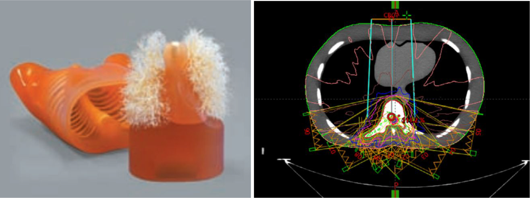
The anthropomorphic thorax phantom (left) and the field setup of a treatment plan developed using the phantom (right).
The plan was delivered on a Varian TrueBeam linear accelerator (Varian Medical Systems, Palo Alto, CA) with console software version v2.7, and kV and MV images were automatically acquired during plan delivery with Varian’s proprietary software iTools Capture. The kV imager (model 4030CB) has a physical dimension of 40 cm × 30 cm with an image matrix of 1024 × 768 and a pixel size of 0.388 mm. The MV panel (model AS1200) has a physical dimension of 43cm × 43cm with an image matrix of 1280 × 1280 and a pixel size of 0.336 mm. Given a source-to-imager distance (SID) of 150 cm and a source-to-axis distance (SAD) of 100cm, the effective pixel sizes at the isocenter are 0.259 mm and 0.224 mm, respectively, for the KV and MV images. The MV images were continuously acquired with a frame rate of 11.4 fps, while the KV images were triggered at every 500 MU during radiation delivery. Both MV and kV images were acquired with dark-field corrections and flood-field corrections.
2.2. High-resolution DRRs as matching templates
Motion tracking was achieved by registering on-treatment MV and KV images to our customized digitally reconstructed radiograph (DRR) templates. To improve the accuracy of registration, high-resolution spine-only DRR templates were created from retrospectively reconstructed CBCT reconstructions with an isotropic voxel size of (0.243 mm)3. The high resolution CBCT was obtained by sending acquired raw projections to a Varian proprietary software program (namely iTools Reconstruction) to compute a CBCT volume with a customizable voxel size and the same reconstruction algorithm as used in clinic. On a stand-alone workstation (Intel Xeon CPU@2.1GHz, 32GB DDR, 64-bit Windows 10), a CBCT reconstruction with matrix size of 1024×1024×700 takes less than 4 minutes on CPU, which can be further reduced with GPU implementation and should not delay clinical workflow. The orientation of the high-resolution CBCT was corrected by CBCT to planning CT registration to match the actual treatment position. An in-house software using detector pixel-driven forward projection algorithm was employed for the DRR template calculations for all planned MV-beam angles and KV-beam angles. Figure 2 shows three spine-only DRR templates generated with CBCT voxel sizes of 0.243×0.243×0.243 mm3, 1×1×1 mm3, and 1×1×2 mm3, respectively. Higher-resolution DRRs have clearly sharper edges thus leading to less uncertainty for image matching.
Figure 2.
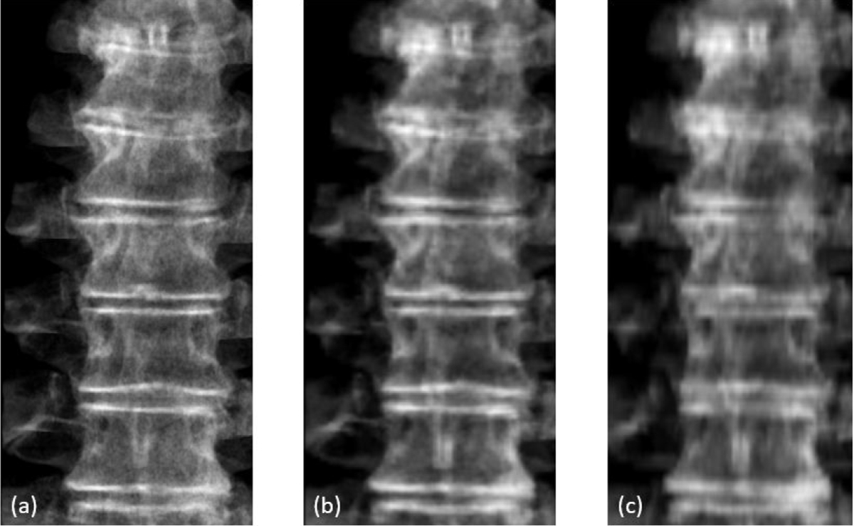
Comparison of DRRs created from CBCT with different voxel size: (a) 0.243×0.243×0.243 mm3, (b) 1×1×1 mm3, and (c) 1×1×2 mm3.
2.3. MV image preprocessing
During the treatment delivery, about 400 to 500 frames of raw MV images were collected for each gantry angle. However, as the sliding-window IMRT technique utilizes a set of small MLC apertures, it is not always possible to visualize useful landmarks in a single MV frame for reliable image matching. To solve this issue, an enhanced synthetic treatment beam (ESTB) imaging technique was used (Li et al 2021). The main idea of this technique is to combine multiple continuous MV frames, after scatter reduction and beam intensity variation corrections, to generate a synthetic MV image with enlarged field of view (FOV). Depending on the plan and patient anatomy, combining 50 to 100 consecutive frames is usually sufficient to produce synthetic MV images with reasonable FOV sizes for matching on spine structures. The frame combining process had an inherent time delay of 5–10 seconds, which was deemed acceptable for spine motion detection because the motions were typically not continuous but random spontaneous bulk motions.
2.4. Motion tracking
To determine 3D motion, a pair of a synthetic MV image and an on-treatment kV image were firstly registered to their respective DRR templates separately for 2D matching. The 2D results were then used to triangulate the 3D shift. To demonstrate feasibility of the technique and to ensure matching accuracy, MV-to-DRR and kV-to-DRR registrations were performed manually for each beam. An automatic registration approach using mutual information (MI) was also evaluated with the region of interest (ROI) selected as projected PTV contour plus 1 cm margin. Figure 3 shows the coordinate system of simultaneous MV and kV image acquisition on a linear accelerator gantry system. Both MV and kV images were scaled to isocenter. From MV-to-DRR registration, we have
| (1) |
where qMV and PMV are shifts in the vertical and horizontal direction, respectively, on the MV imaging plane, and dx, dy, and dz are 3D shifts in the patient’s coordinate system in lateral (left +), vertical (posterior +) and longitudinal (superior +) directions. Image acquisition angle GMV is defined in the gantry system and is converted to patient’s coordinate system by subtracting 90 degrees. Similarly, for kV-to-DRR registration, we have
| (2) |
Figure 3.
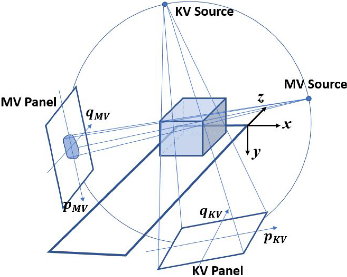
Geometry of motion tracking with simultaneous MV-kV imaging on a conventional linear accelerator.
Note that GKV = GMV − 90 in gantry system. Then the motion in patient system is calculated as
| (3) |
The entire procedure is summarized in the flowchart in Figure 4.
Figure 4.
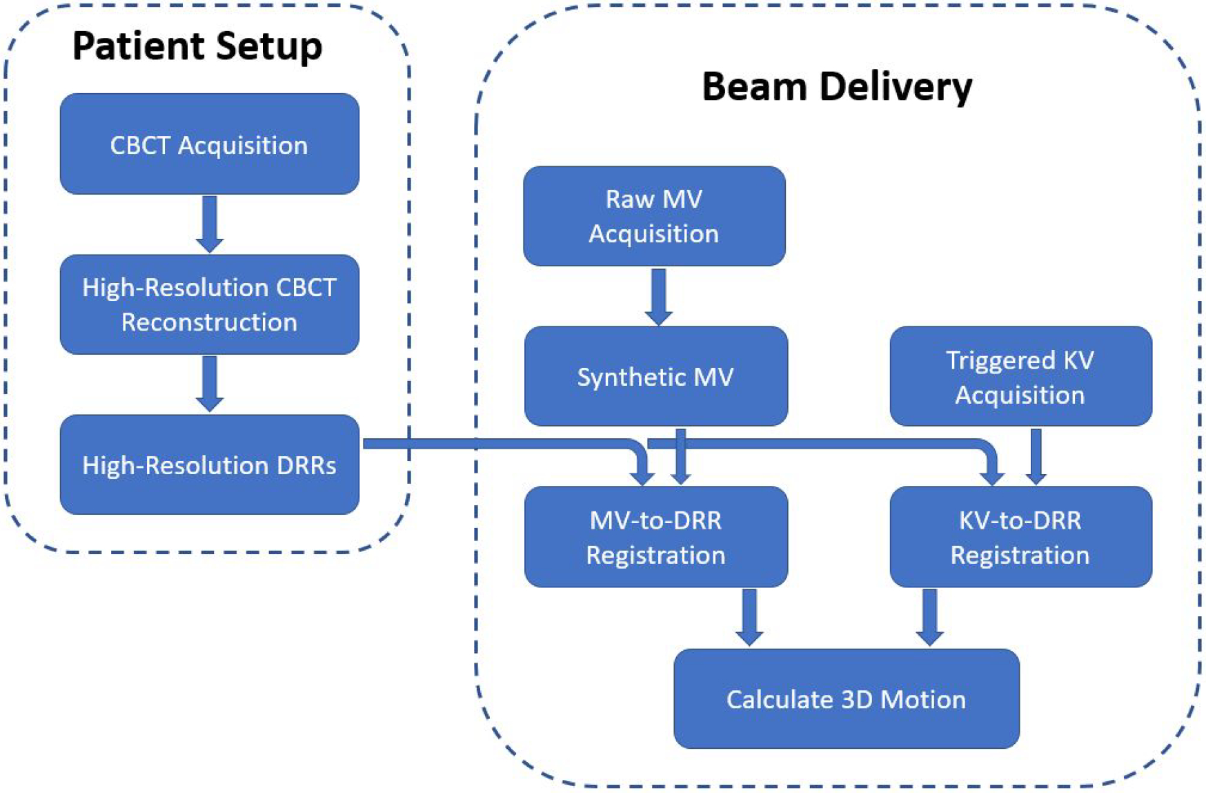
Flowchart of the proposed approach of motion tracking using orthogonal MV and KV images
2.5. Study Design
A phantom study was designed to quantify the accuracy of motion tracking. The LUNGMAN phantom was placed on the couch and aligned to the planning position using a cone beam CT scan. High resolution DRR templates were then calculated using the same cone beam CT acquisition. During beam delivery, the MV and KV images were acquired for the nine MV beam angles (180, 160, 140, 120, 100, 260, 240, 220 and 200 degrees) and the corresponding KV angles (90, 70, 50, 30, 10, 170, 150, 130, 110 degrees). The phantom was then shifted by 2 mm in 1) the longitudinal direction only, 2) the lateral direction only, 3) the vertical direction only, and 4) all three directions, respectively, to simulate patient motions after the initial setup. The acquired MV and KV images were retrospectively analyzed using DRR template matching to calculate 3D shifts, and the errors were analyzed. For comparison, motions detected with a single kV image or a single MV image were also analyzed.
In addition to the phantom study, two patients receiving paraspinal SBRT were retrospectively investigated under an ongoing IRB-approved clinical protocol. The first patient was treated to T8-T9 vertebral bodies, where the diaphragm could bring in uncertainties for registration. For this case, the tracking results using both manual registration and automatic mutual information-based registration were compared. The second patient was treated to L3-L5 vertebral bodies, where MV and kV image quality might be compromised by thick patient body. This dataset was also analyzed to demonstrate the potential impact of time window width for creating synthetic MV images. Both were planned with ECHO using the standard 9-fields template (same gantry angles as in the phantom study) with 6xFFF beams. The prescribed doses were both 2700cGy in three fractions. In addition, two CBCT scans were acquired for each patient, one before the treatment for the patient setup, and the other at the end of the treatment for validating the final motion.
3. RESULTS
3.1. Phantom Study
Figure 5 shows an example of a simultaneous MV-kV image pair used for motion tracking. The synthetic MV image and the triggered on-treatment kV image were obtained at a gantry angle of 180 degrees (kV source was at 90 degrees counterclockwise from the MV source). The synthetic MV image contained 200 continuous frames, with a window interval of 18 seconds. The contrast-to-noise ratio (CNR) around vertebral body edges is generally 2.5 – 3.8 in the synthetic MV image and 3.2 – 5.5 in the KV image.
Figure 5.
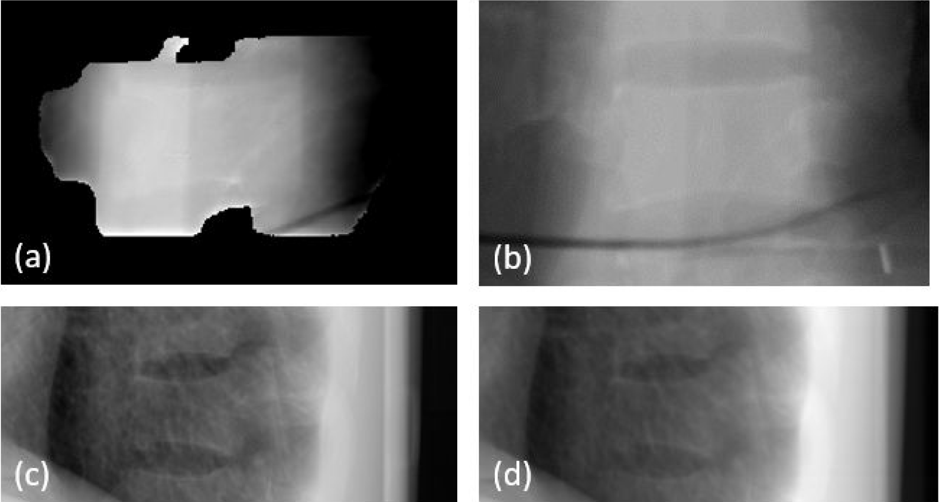
Example of phantom images: (a) synthetic MV image at gantry angle of 180 degree, (b) DRR at MV angle, (c) kV image at kV angle of 90 degree and (d) DRR at KV angle.
The treatment plan was delivered to the phantom for the following five scenarios: no shift, 2 mm shift in one of the longitudinal, lateral and vertical directions, and 2 mm shift in all three directions. As an example, Figure 6 demonstrates the detected 3D shifts for all nine beams for the scenario of 2mm lateral shift in the temporal order of delivery. Table 1 summarizes the detected shifts for all the five scenarios in terms of average shift and standard deviation in each direction. The errors between ground truth (actual shift) and the mean values of detected shifts (over nine beams) are listed as well, which were all less than 0.15mm. All standard deviations (over nine beams) are within 0.15mm. It is estimated that the uncertainty of tracking error should be less than 0.30mm, which includes 0.15mm for the error of mean and 0.15mm for the standard deviation.
Figure 6.
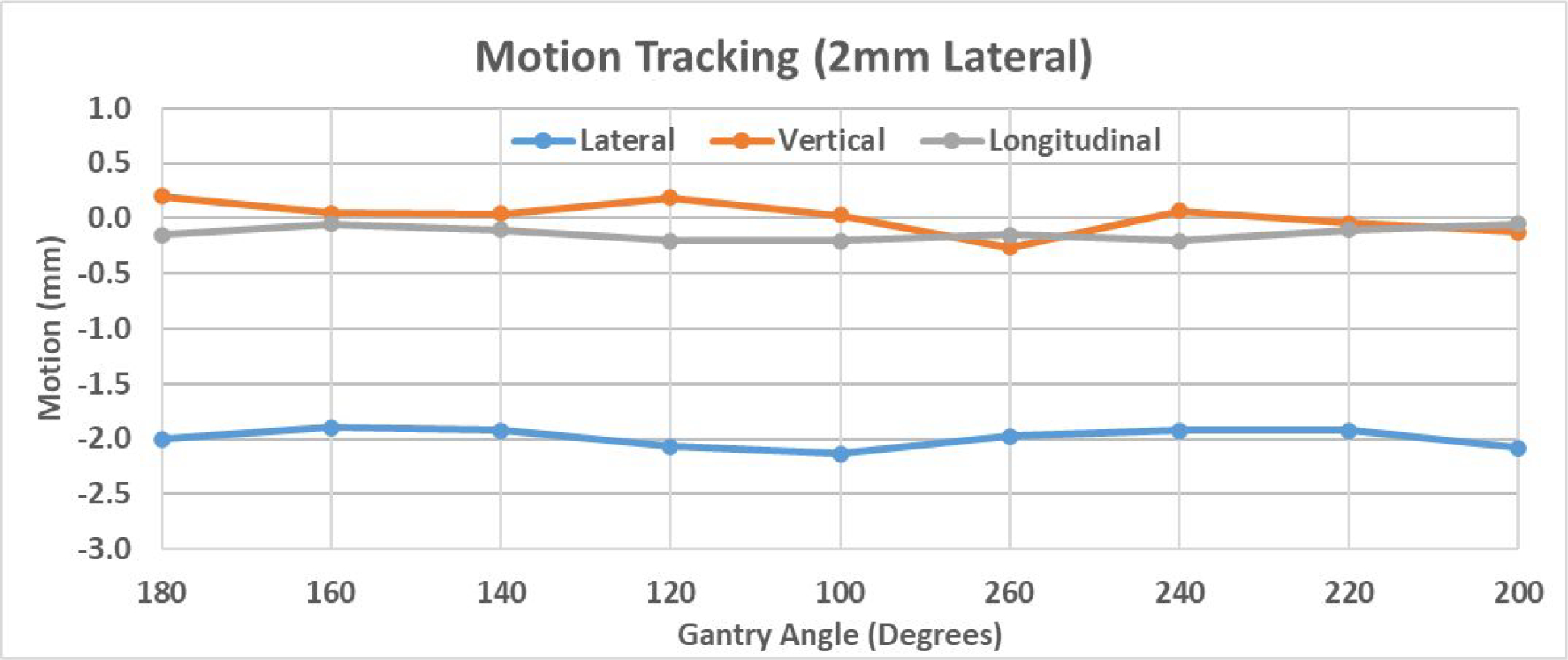
Demonstration of 3D shift detected by MV-KV approach in the scenario of a 2mm shift in the lateral direction.
Table 1.
Summary of detected phantom shifts for the five scenarios
| Lateral | Vertical | Longitudinal | ||||
|---|---|---|---|---|---|---|
| Mean (Std) (mm) | Error (mm) | Mean (Std) (mm) | Error (mm) | Mean (Std) (mm) | Error (mm) | |
| No Shift | 0.00 (0.09) | 0.00 | 0.04 (0.06) | 0.04 | −0.15 (0.07) | −0.15 |
| 2mm Lng | 0.06 (0.08) | 0.06 | 0.07 (0.13) | 0.07 | −2.13 (0.08) | −0.13 |
| 2mm Vrt | 0.05 (0.10) | 0.05 | −1.92 (0.05) | 0.08 | −0.12 (0.04) | −0.12 |
| 2mm Lat | −1.99 (0.09) | 0.01 | 0.02 (0.14) | 0.02 | −0.13 (0.06) | −0.13 |
| 2mm All | −2.04 (0.10) | −0.04 | −1.94 (0.11) | 0.06 | −2.01 (0.10) | −0.01 |
As a comparison to simultaneous MV-kV imaging, it is also meaningful to see the motion detection accuracy using just the kV or MV imaging alone. As an example, Figure 7 demonstrates the results for the case of 2 mm lateral shift. With the coordinate system defined in Figure 3, the q axes of both MV and KV panels are parallel to the couch’s longitudinal direction, and thus q values represent the longitudinal shifts of the phantom for all gantry angles. The direction of p axes, however, changes with gantry angles, and thus p shifts are not directly related to shifts in the coordinates of the couch. Therefore, detected shifts in p direction are less meaningful for adjusting couch position.
Figure 7.
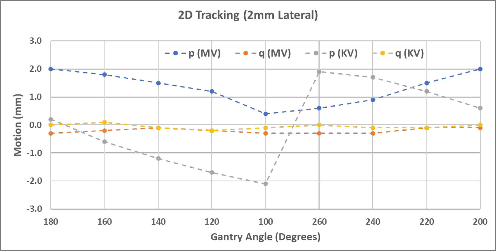
Shifts detected by single kV or MV images in the detector p-q plane in the scenario of a 2mm lateral shift.
3.2. Patient Study
The first patient was treated at T8-T9 vertebral bodies. Figure 8 shows example images including (a) the synthetic MV image at gantry angle of 180 degree, (b) the kV image at kV beam angle of 90 degree, and (c) and (d) the high-resolution bone-only DRR templates at their respective angles. The synthetic MV images were calculated using the first 300 raw MV frames of each beam. Note that the diaphragm was visible and overlapping with the spine targets at several imaging angles, which could bring errors in MI-based registration due to significant respiratory motion. To minimize such an impact, bone-only DRRs were created where the diaphragm was eliminated. To ensure the accuracy of image registrations, manual matching was also performed, and the results are shown (solid curves) in Figure 9 together with MI-based registration results (dashed curves). MI-based results were in good agreement with the manual results in the three directions. Their differences, calculated as absolute errors, are summarized in Table 2. For all three directions, the average difference is less than 0.18mm, and the majority (75% percentile) of the differences are smaller than 0.27mm. Since the patient underwent one CBCT for initial setup and a second CBCT right after beam delivery, the two CBCTs can be compared to show the final motions after treatment, which were (shifts only): −0.4mm laterally, −0.6mm vertically and 0.7mm longitudinally. This agreed well with MV-kV tracking results using manual registration at the last beam angle (200 degrees), which were 0.0mm, −0.2mm and 0.6mm, respectively.
Figure 8.
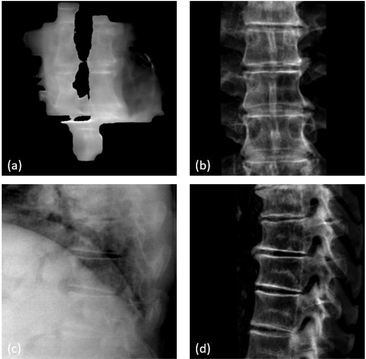
T-spine patient images: (a) synthetic MV image at gantry angle of 180 degrees, (b) DRR at MV angle, (c) KV image at KV angle of 90 degrees, and (d) DRR at kV angle.
Figure 9.
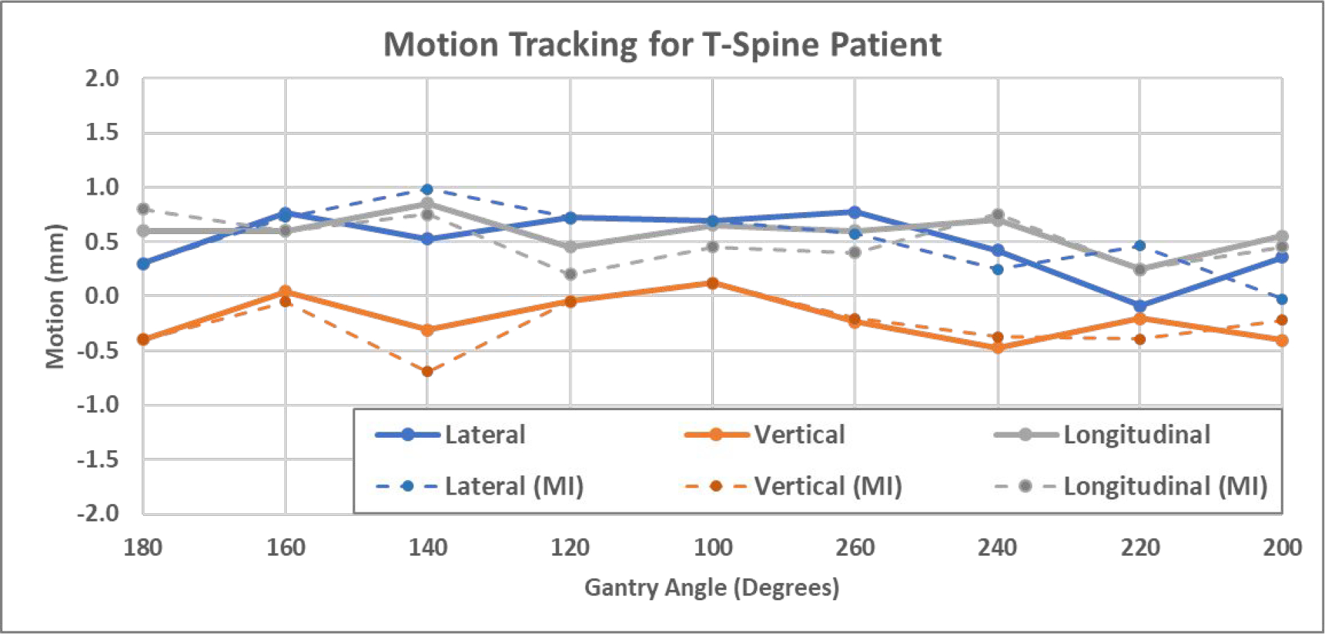
3D shifts of the T-spine patient calculated using both manual registration (solid) and MI-based registration (dashed).
Table 2.
Summary of absolute errors between manual results and MI-based results for patient studies
| Mean (mm) | STD (mm) | Max (mm) | Quart-75% (mm) | |
|---|---|---|---|---|
| T-spine patient | ||||
| Lateral | 0.16 | 0.19 | 0.61 | 0.18 |
| Vertical | 0.18 | 0.18 | 0.51 | 0.27 |
| Longitudinal | 0.17 | 0.20 | 0.65 | 0.20 |
| L-spine patient | ||||
| Lateral | 0.12 | 0.11 | 0.28 | 0.15 |
| Vertical | 0.15 | 0.10 | 0.29 | 0.21 |
| Longitudinal | 0.14 | 0.05 | 0.23 | 0.15 |
The second patient was treated at L3-L5 vertebral bodies. Figures 10 shows examples of MV, kV and DRR images, and Figure 11 shows 3D shifts calculated based on the MV-kV images. The second CBCT confirmed the motion was 0.7mm laterally, −0.3mm vertically and −0.6mm longitudinally. This agreed well with detected shifts using MV-kV tracking at the last beam (200 degrees), which were 0.4mm, −0.1mm and −0.5mm, respectively.
Figure 10.
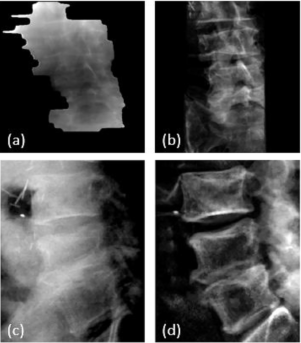
L-spine patient images: (a) synthetic MV image at gantry angle of 180 degrees, (b) DRR at MV angle, (c) kV image at kV angle of 90 degrees and (d) DRR at kV angle.
Figure 11.
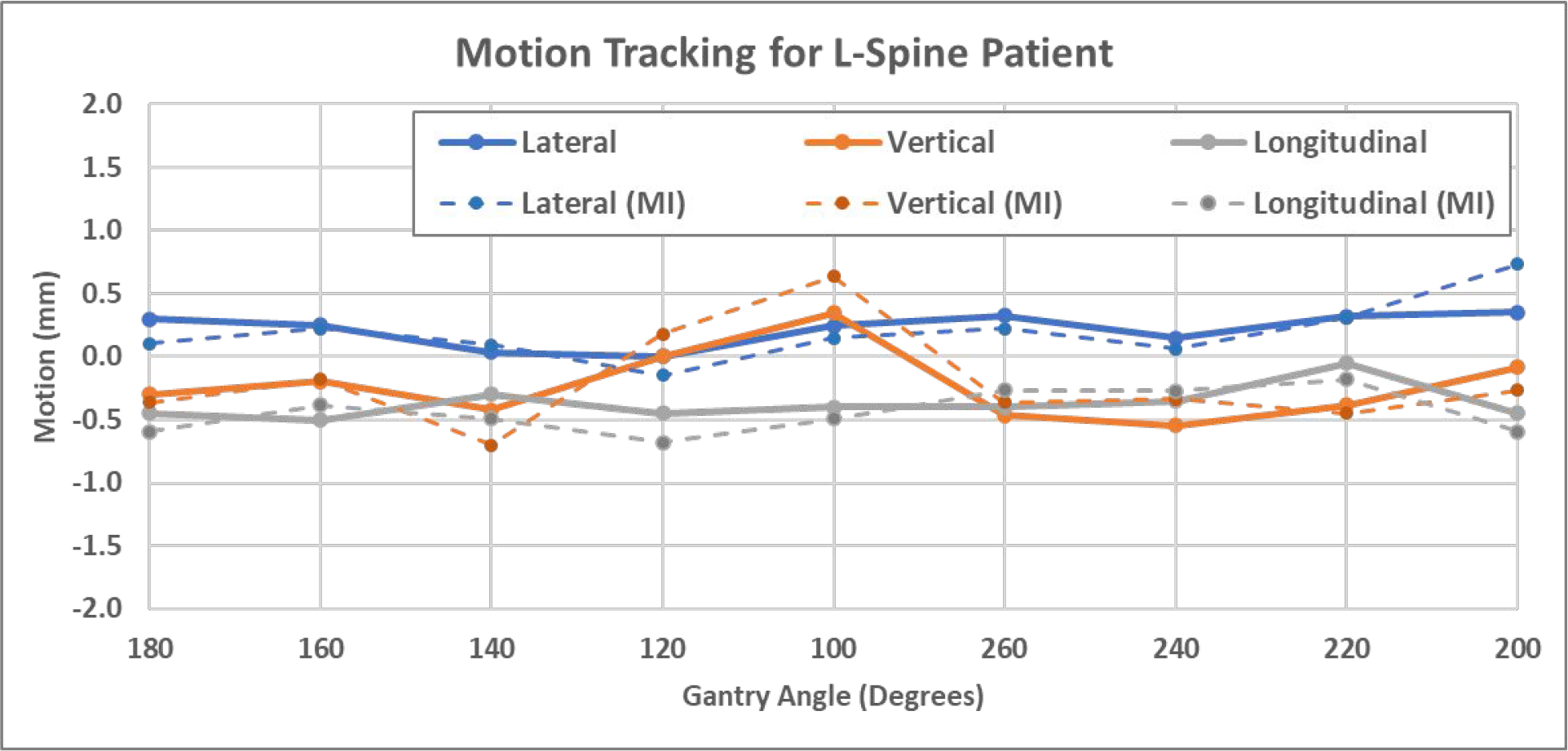
3D shifts of the L-spine patient calculated using manual registration (solid) and MI-based registration (dashed).
4. DISCUSSION
The proposed MV-kV motion tracking technique was quantitatively evaluated through a phantom study and further validated with two patient studies. The detected 3D shifts agreed well with the physical setup with an uncertainty of less than 0.3mm in all phantom studies. The patient study demonstrated that the proposed MV-kV motion tracking approach worked as expected for T-spine and L-spine treatment in a clinical setting.
MV-kV images provide complementary tracking information from orthogonal views, which is especially favorable over a single image system if one of the images shows inferior quality. For example, certain lateral kV images might show inferior image quality for large patients, however, the simultaneous MV images from the anterior-posterior direction usually show good image quality due to shorter x-ray path through the patient.
The MV-kV formulism was constructed based on the assumption of a perfect geometry, i.e. the mechanical isocenter is aligned perfectly with the kV imaging isocenter and the MV radiation isocenter. In reality, geometrical errors are introduced into the system by several sources, of which the main source is gantry sagging. For the linear accelerator systems used for this study, gantry sagging is about 0.22mm according to the vendors routine Preventive Maintenance Inspections (PMI). At this magnitude, gantry sagging may bring in some errors at certain gantry angles. This effect is already included in the uncertainty of 0.3mm in the phantom study.
The temporal resolution of tracking is basically determined by the length of the time window used for calculating synthetic MV images, and this time period can be shortened with the trade-off of increased registration uncertainties. Synthetic MV images can be calculated using raw MV frames acquired within different time windows (Li et al 2021) and they produce different regions of a patient’s anatomy with different MLC aperture sizes and shapes. As the example shown in Figure 12, the synthetic MV images were calculated for the beam at 100° gantry angle, where a total of 402 raw MV frames were collected. Figure 12(a) shows the synthetic MV image by combining all 402 raw MV frames, and (b) and (c) were obtained by combining 200 raw MV frames (frames 1–200 and 201–400), both of which showed sufficient FOV and decent anatomy contrast. Figures 12(d), 12(e) and 12(f) were selected from 100-frame combinations, using frames 1–100, 101–200 and 201–300, respectively. The FOVs were smaller and anatomies that can be useful for registration were limited. Figures 12(g), 12(h) and 12(i) were selected from 50-frame combinations (frames 1–50, 101–150 and 301–350), where useful anatomies shown in MLC apertures are very limited, thereby causing more uncertainties in MV-to-DRR registration. Deep learning-based rigid image registration approaches could be a helpful in automatically identifying meaningful image features and improving detection sensitivity and accuracy even with a smaller MV aperture, which are being investigated by our group. Neural network models for optical flow estimation approaches (Teo et al 2019 and Shi et al 2021) are a potential direction for improving the accuracy and efficiency of automatic motion detection.
Figure 12.
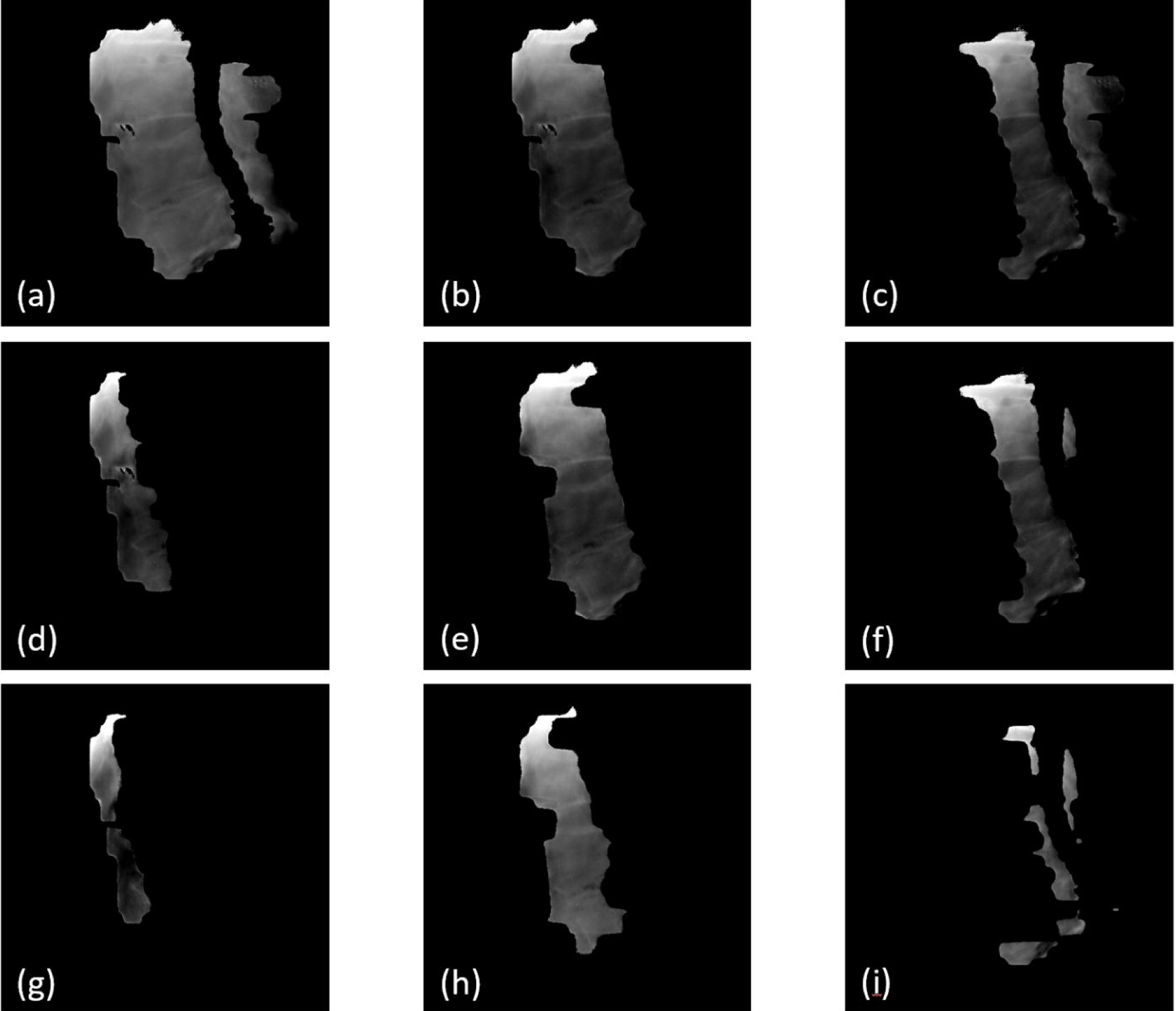
Synthetic MV images calculated by combining raw MV frames acquired in various time windows. (a) was calculated by combining all 402 raw MV frames; (b) and (c) are 200-frame combinations (frames 1–200 and 201–400, respectively); (d), (e) and (f) are 100-frame combinations (frames 1–100, 101–200 and 201–300), respectively; (g), (h) and (i) are 50-frame combinations (frames 1–50, 101–150 and 301–350, respectively).
The proposed MV-kV motion tracking approach for spinal treatment is not limited to IMRT beams at static gantry angles, and it can be expanded to volume modulated arc therapy (VMAT) plans with some modifications. As previously reported, the MV-kV technique has been used for motion tracking in prostate SBRT (Happersett et al 2019, Hunt et al 2016, Crotteau et al 2022). In this technique, when KV is triggered, MLC apertures are open wider to expose at least one fiducial and the dose rate is reduced to acquire MV images (Happersett et al 2019). This idea can be adapted for VMAT spinal treatment in the future.
It should be noted that only translational motions were considered in this study. 2D-2D registration tracks translational motion very well, and in many cases, it can give good estimates to correct for rotational motions (pitch, roll and yaw) by applying translational shifts only, as long as the center of rotational motion is away from PTV (which is often the case). This has been reported in MV-KV imaging-based motion tracking for prostate SBRT (Zhang et al 2016, Gorovets et al 2020, Happersett et al 2019, Hunt et al 2016, Crotteau et al 2022). However, in some cases, it is the intrinsic limitation that a 2D-2D registration together with translational shift cannot correct motion with rotational motion. 2D-3D registration algorithm can be applied to generate six-degree of freedom shifts (Furtado et al 2014, Munbodh et al 2014, Kuo et al 2020). However, for the task of motion detection (rather than realignment), 2D-2D registration is sufficient (Fan et al 2021).
While manual registration was used in this study as the golden standard, mutual information-based registration was also tested for patients to demonstrate the feasibility of automated MV-kV tracking in real clinical settings. MI-based registration is readily available for kV-to-DRR registration, and it generally worked well for MV-to-DRR registration if an appropriate ROI is defined. Our group is also working on novel methods to enhance kV and MV images and to segment bones out of KV and MV images to achieve more accurate and reliable automatic registration (He et al 2022). The manual matching results were also validated by the second CBCT scan, which further confirmed the feasibility of using our proposed MV-kV method in a clinic setting.
To implement the MV-KV tracking technique in clinical settings, there are some challenges that should be noted. A standalone workstation should be configured to efficiently perform high-resolution CBCT reconstruction and calculate DRR templates. The quality of MV and KV images and visibility of relevant anatomies vary across patients and view angles, which might produce uncertainties and failures in registration. These should be evaluated through pilot patient studies to determine action levels. The patient should be re-imaged and repositioned if motion exceeds thresholds.
5. CONCLUSIONS
The MV-KV imaging-based markerless motion tracking technique for paraspinal SBRT treatments was validated through a feasibility study. This technique can be readily integrated with our current clinical workflow, and it provides the radiation therapists with quantitative information of patient motion during beam delivery. This research is a step forward toward more effective motion tracking and accurate treatment delivery for spine SBRT.
ACKNOWLEDGEMENTS
Memorial Sloan Kettering Cancer Center has a research agreement with Varian Medical Systems. This research was partially supported by the NIH/NCI Cancer Center Support Grant/Core Grant (P30 CA008748).
References
- Bertholet J, Knopf A, Eiben B, et al. 2019. Real-time intrafraction motion monitoring in external beam radiotherapy Phys. Med. Biol. 64(15) 15TR01. [DOI] [PMC free article] [PubMed] [Google Scholar]
- Bryant J, Rottmann J, Lewis J, Mishra P, Keall P and Berbeco R 2014. Registration of clinical volumes to beams-eye-view images for real-time tracking Med. Phys. 41(12) 121703. [DOI] [PMC free article] [PubMed] [Google Scholar]
- Crotteau K, Lu W, Berry S, Happersett L, Burleson S and Cai W 2022. Retrospective analysis of MV-kV imaging-based fiducial tracking in prostate SBRT treatment J. Appl. Clin. Med. Phys. 23(6) e13593. [DOI] [PMC free article] [PubMed] [Google Scholar]
- De Bruin K, Dahele M, Mostafavi H, Slotman Band Verbakel W 2021. Markerless real-time 3-demensional kV tracking of lung tumors during free breathing stereotactic radiation therapy Adv. Radiat. Oncol. 6(4) 100705. [DOI] [PMC free article] [PubMed] [Google Scholar]
- Fan Q, Pham H, Zhang P, Li X, Li T 2022. Evaluation of a proprietary software application for motion monitoring during stereotactic paraspinal treatment J. Appl. Clin. Med. Phys. 23(6) e13594. [DOI] [PMC free article] [PubMed] [Google Scholar]
- Furtado H, Steiner E, Stock M, Georg D, Birkfellner W 2014. Real-time intensity based 2D/3D registration using kV-MV image pairs for tumor motion tracking in image guided radiotherapy Proc. SPIE 9034 90340H. [DOI] [PubMed] [Google Scholar]
- Furweger C, Drexler C, Kufeld M, Muacevi A and Wowra B 2011. Advances in fiducial-free image-guidance for spinal radiosurgery with CyberKnife - a phantom study J. Appl. Clin. Med. Phys. 12(2) 20–28 [DOI] [PMC free article] [PubMed] [Google Scholar]
- Gorovets D, Burleson S, Jacobs L, et al. 2020. Prostate SBRT With Intrafraction Motion Management Using a Novel Linear Accelerator-Based MV-kV Imaging Method Pract. Radiat. Oncology. 10(5) e388–e396 [DOI] [PubMed] [Google Scholar]
- Graeper G, Cetnar A, Ayan A and Weldon M 2021. Interpretation of intrafraction motion review data and method for verification J. Appl. Clin. Med. Phys. 22(11) 196–202 [DOI] [PMC free article] [PubMed] [Google Scholar]
- Greco C, Pares O, Pimentel N, Moser E, Louro V, Morales X, Salas B and Fuks Z 2015. Spinal metastases: From conventional fractionated radiotherapy to single-dose SBRT Reports of Practical Oncology & Radiotherapy 20(6) 454–463 [DOI] [PMC free article] [PubMed] [Google Scholar]
- Gurney-Champion O, Dahele M, Mostafavi H, Slotman B and Verbakel W 2013. Digital tomosynthesis for verifying spine position during radiotherapy: a phantom study Phys. Med. Biol. 58(16) 5717–5733 [DOI] [PubMed] [Google Scholar]
- Hall W, Stapleford L, Hadjipanayis C, Curran W, Crocker I and Shu H 2011. Stereotactic body radiosurgery for Spinal Metastatic Disease: an evidence-based review Int. J. Surg. Onc. 2011: 979214. [DOI] [PMC free article] [PubMed] [Google Scholar]
- Happersett L, Wang P, Zhang P, et al. 2019. Developing a MLC modifier program to improve fiducial detection for MV/kV imaging during hypofractionated prostate volumetric modulated arc therapy J. Appl. Clin. Med. Phys. 20(6) 120–124 [DOI] [PMC free article] [PubMed] [Google Scholar]
- Hazelaar C, Verbakel W, Mostafavi H, van der Weide L, Slotman B and Dahele M 2018. First experience with markerless online 3D spine position monitoring during SBRT delivery using a conventional LINAC Int. J. Radiat. Oncol. Biol. Phys. 101(5) 1253–1258 [DOI] [PubMed] [Google Scholar]
- He X, Cai W, Li F, Fan Q, Zhang P, Cuaron J, Cerviño L, Li X and Li T 2021. Decompose kV projection using neural network for improved motion tracking in paraspinal SBRT Med. Phys. 48(12) 7590–7601 [DOI] [PMC free article] [PubMed] [Google Scholar]
- Ho A, Fu D, Hancock S, et al. 2007. A study of the accuracy of CyberKnife spinal radiosurgery using skeletal structure tracking Neurosurgery 60(2) ONS147–156 [DOI] [PubMed] [Google Scholar]
- Hunt M, Sonnick M, Pham H, et al. 2016. Simultaneous MV-kV imaging for intrafractional motion management during volumetric modulated arc therapy delivery J. Appl. Clin. Med. Phys. 17(2) 473–486 [DOI] [PMC free article] [PubMed] [Google Scholar]
- Jiang S, Lu Y, Li H, Hartley R 2021. Learning optical flow from a few matches CVPR 2021 16592–16600 [Google Scholar]
- Jin J, Yin F, Tenn SE, Medin PM and Solberg T 2008. Use of the BrainLAB ExacTrac X-Ray 6D System in Image-Guided Radiotherapy Med. Dosi. 33(2) 124–134 [DOI] [PubMed] [Google Scholar]
- Kaur G, Lehmann J, Greer P and Simpson J 2019. Assessment of the accuracy of truebeam intrafraction motion review (IMR) system for prostate treatment guidance Australas. Phys. Eng. Sci. Med. 42(2) 585–598 [DOI] [PubMed] [Google Scholar]
- Keall P, Nguyen D, O’Brien R, et al. 2018. Review of real-time 3D IGRT on standard-equipped cancer radiotherapy systems: are we at the tipping point for the era of real-time radiotherapy Int. J. Radiat. Oncol. Biol. Phys. 102(4) 922–931 [DOI] [PMC free article] [PubMed] [Google Scholar]
- Kim J, Nguyen D, Booth J, et al. 2018a. The accuracy and precision of Kilovoltage Intrafraction Monitoring (KIM) six degree-of-freedom prostate motion measurements during patient treatments Radiother. and Oncol. 126(2) 236–243 [DOI] [PubMed] [Google Scholar]
- Kim J, Park Y, Edmunds D, Oh K, Sharp G and Winey B 2018b. Kilovoltage projection streaming-based tracking application (KiPSTA): first clinical implementation during spine stereotactic radiation surgery Adv in Radiat. Oncol. 3(4) 682–692 [DOI] [PMC free article] [PubMed] [Google Scholar]
- Kuo H, Lovelock M, Li G, Ballangrud A, Wolthuis B, Della-Biancia C, Hunt M and Berry S 2020. A phantom study to evaluate three different registration platform of 3D/3D, 2D/3D, and 3D surface match with 6D alignment for precise image-guided radiotherapy J. Appl. Clin. Med. Phys. 21(12) 188–196 [DOI] [PMC free article] [PubMed] [Google Scholar]
- Li T, Li F, Cai W, Zhang P and Li X 2021. Technical Note: Synthetic treatment beam imaging for motion monitoring during spine SBRT treatments - a phantom study Med. Phys. 48(1) 125–131 [DOI] [PMC free article] [PubMed] [Google Scholar]
- Mishra P, Li R, Mak R, Rottmann J, Bryant J, Williams C, Berbeco R and Lewis J 2014. An initial study on the estimation of time-varying volumetric treatment images and 3D tumor localization from single MV cine EPID images Med. Phys. 41(8) 081713. [DOI] [PMC free article] [PubMed] [Google Scholar]
- Montgomery C and Collins M 2017. An evaluation of the BrainLAB 6D ExacTrac/Novalis Tx system for image-guided intracranial radiotherapy J. Radiother. Pract. 16(3) 326–333 [Google Scholar]
- Munbodh R and Moseley D 2014. 2D-3D registration for brain radiation therapy using a 3D CBCT and a single limited field-of-view 2D kV radiograph J. Phys. Conf. Ser. 489(1) 012037. [DOI] [PubMed] [Google Scholar]
- Nankali S, Worm E, Hansen R, Weber B, Hoyer M, Zirak 2018. A and Poulsen P Geometric and dosimetric comparison of four intrafraction motion adaption strategies for stereotactic liver radiotherapy Phys. Med. Biol. 63 145010. [DOI] [PubMed] [Google Scholar]
- Roggen T, Bobic M, Givehchi N and Scheib S 2020. Deep learning model for markerless tracking in spinal SBRT Phys. Med. 74 66–73 [DOI] [PubMed] [Google Scholar]
- Rozario T, Chiu T, Chen M, Jia X, Lu W, Bereg S and Mao W 2018. A novel markerless lung tumor-tracking method using treatment MV beam imaging Appl. Sci. 8(12) 2525 [Google Scholar]
- Saenz D, Crownover R, Stathakis S and Papanikolaou N 2019. A dosimetric analysis of a spine SBRT specific treatment planning system J. Appl. Clin. Med. Phys. 20(1) 154–159 [DOI] [PMC free article] [PubMed] [Google Scholar]
- Shieh C, Keall P, Kuncic Z, Huang C, Feain I 2015. Markerless tumor tracking using short kilovoltage imaging arcs for lung image-guided radiotherapy Phys Med. Biol. 60(24) 9437. [DOI] [PMC free article] [PubMed] [Google Scholar]
- Teo PT, Guo K, Ahmed B, Alayoubi N, Kehler K, Fontaine G, Sasaki D and Pistorius S 2019. Evaluating a potential technique with local optical flow vectors for automatic organ-at-risk (OAR) intrusion detection and avoidance during radiotherapy Phys. Med. Biol. 64 145008. [DOI] [PubMed] [Google Scholar]
- Van Sornsen de Koste J, Dahele M, Mostafavi H, Sloutsky A, Senan S, Slotman B, Verbakel W 2015. Markerless tracking of small lung tumors for stereotactic radiotherapy Med. Phys. 42(4) 1640–1652 [DOI] [PubMed] [Google Scholar]
- Vellayappan B, Chao S, Foote M, Guckenberger M, Redmond K, Chang E, Mayr N, Sahgal A and Lo S 2018. The evolution and rise of stereotactic body radiotherapy (SBRT) for spinal metastases Expert Review of Anticancer Therapy 18(9) 887–900 [DOI] [PubMed] [Google Scholar]
- Verbakel W, Gurney-Champion O, Slotman B and Dahele M 2015. Sub-millimeter spine position monitoring for stereotactic body radiotherapy using offline digital tomosynthesis Radiother. and Oncol. 115(2) 223–228 [DOI] [PubMed] [Google Scholar]
- Yue Y, Aristophanous M, Rottmann J, Berbeco R 2011. 3-D fiducial motion tracking using limited MV projections in arc therapy Med. Phys. 38(6) 3222–3231 [DOI] [PubMed] [Google Scholar]
- Zarepisheh M, Hong L, Zhou Y, Oh J, Mechalakos J, Hunt M, Mageras G, Deasy J 2019. Automated intensity modulated treatment planning: The expedited constrained hierarchical optimization (ECHO) system Med. Phys. 46(7) 2944–2954 [DOI] [PMC free article] [PubMed] [Google Scholar]
- Zeng K, Tseng C, Soliman H, Weiss Y, Sahgal A and Myrehaug S 2019. Stereotactic Body Radiotherapy (SBRT) for Oligometastatic Spine Metastases: An Overview Frontiers in Oncology 9 337. [DOI] [PMC free article] [PubMed] [Google Scholar]
- Zhang P, Happersett L, Ravindranath B, et al. 2016. Optimizing fiducial visibility on periodically acquired megavoltage and kilovoltage image pairs during prostate volumetric modulated arc therapy Med. Phys. 43(5) 2024. [DOI] [PMC free article] [PubMed] [Google Scholar]


