

Abstract
199Three-dimensional (3D) scaffolds composed of various biomaterials, including metals, ceramics, and synthetic polymers, have been widely used to regenerate bone defects. However, these materials possess clear downsides, which prevent bone regeneration. Therefore, composite scaffolds have been developed to compensate these disadvantages and achieve synergetic effects. In this study, a naturally occurring biomineral, FeS2, was incorporated in PCL scaffolds to enhance the mechanical properties, which would in turn influence the biological characteristics. The composite scaffolds consisting of different weight fractions of FeS2 were 3D printed and compared to pure PCL scaffold. The surface roughness (5.77-fold) and the compressive strength (3.38-fold) of the PCL scaffold was remarkably enhanced in a dose-dependent manner. The in vivo results showed that the group with PCL/ FeS2 scaffold implanted had increased neovascularization and bone formation (2.9-fold). These results demonstrated that the FeS2 incorporated PCL scaffold might be an effective bioimplant for bone tissue regeneration.
Keywords: FeS2, PCL, 3D printed, Mechanical properties, Bone formation
1. Introduction
Bone is a dynamic tissue with a hierarchical structure composed of organic and inorganic components[1]. This complex tissue is responsible for important body functions, including locomotion, framework, as well as support and protection of internal organs[2]. The hierarchical and complex structure of the bone offers exceptional mechanical properties, which contributes to load-bearing functions[3]. Bones have the ability to 200self-repair without forming scar tissue when fractured through the bone healing process[4]. This process is based on a cascade of events, which include the restoration of vascularity, recruitment of adjacent cells, ossification, etc.[5]. However, in severe bone fractures, the bone healing process might be disrupted. In order to aid the healing of severe bone fractures, the use of bone grafts, such as autografts, allografts, and xenografts, has been considered as the ideal method[6]. However, issues including the lack of donors, donor site morbidity, and possibility of infection still prevail since these grafts are donor tissues[7-9].
These shortcomings have compelled the search for an alternative, leading to the development of a new field—tissue engineering. This field aims to restore or replace damaged tissues or organs based on the development of biological substitutes[10]. Viable cells, scaffolds, and growth factors are used to induce tissue development. The bioengineered scaffolds should provide an environment similar to the native tissue or organ to enable the maturation of cells into functional tissue or organ[11]. Therefore, the chemical composition and physical structure should be carefully determined depending on the target tissue. Some of the important characteristics that scaffolds should have for bone tissue engineering applications include mechanical properties matching those of the host tissue, fully interconnected porous structure, and surface properties in favor of cell adhesion, proliferation, and differentiation[12].
Tissue-engineered scaffolds can be fabricated using various techniques. Recently, there has been extensive research on three-dimensional (3D) bioprinting (3DBP), which enables the fabrication of complex 3D structures mimicking the native extracellular matrix structure. The most commonly used 3DBP techniques are inkjet, laser, and extrusion[13-18]. In inkjet printing, the solution is dispensed in the form of droplets through thermal, piezoelectric, or microvalve processes[19]. Although this technique is relatively inexpensive and has high printing speeds, there are some limitations, such as limited bioink viscosity and rapid drying of the bioink post-ejection. In the case of laser-assisted systems, laser is used as the energy source to deposit bioink[20]. Using laser-based methods, high printing resolution can be achieved. However, only photo-crosslinkable bioinks can be used. One of the most common 3DBP techniques is extrusion-based method, where the bioink is extruded using pneumatic pressure or mechanical force[21]. Extrusion-based systems compensates for the limitations of inkjet and laser-based methods. By utilizing the extrusion-based method, heterogeneous structures can be fabricated using various types of biomaterials. Another advantage is that extrusion-based systems are highly customizable, and recently, they have become more affordable.
Various biomaterials such as ceramics, metals, and synthetic polymers have been used to develop tissue-engineered scaffolds for bone tissue regeneration[22-24]. Regardless of their benefits, these biomaterials do not mimic the properties of natural bone tissue. Most metals are not biodegradable, ceramics are very brittle, and most of the synthetic polymers are non-osteoconductive[25-27]. In order to address these problems, blends of synthetic polymers and ceramics have been extensively investigated, benefitting from the favorable properties of each material. Since the main components of bone are composed of ceramic-based materials, ceramics have been used in various regenerative applications[23]. Moreover, the modifiability of synthetic polymers offers a wide variety of applications (Table 1)[28]. Liu et al. fabricated a composite scaffold composed of poly(e-caprolactone) (PCL) and strontium-containing hydroxyapatite (SrHA) using a 3D printing method for bone tissue regeneration[29]. The incorporation of SrHA not 201only improved the mechanical properties of the PCL-based scaffold, but also enhanced the osteogenic activities of the rat bone marrow-derived mesenchymal stem cells in vitro and in vivo. In another study, a PCL/gliadin scaffold was reinforced with mesoporous bioglass fibers of magnesium calcium silicate (mMCS), which improved the compressive strength and degradability of the scaffold[31]. The study found that an increase in mMCS enhanced new bone formation and ingrowth in a rabbit femur defect model. In our previous studies, we fabricated a biocomposite scaffold assembled from PCL and silica particles using a 3D bioprinting system[32,35]. The silica particles enhanced the mechanical properties, which were dependent on the silica size and weight fraction. In vitro results showed that cell proliferation and osteogenic differentiation increased with decreasing silica particle size and increasing silica content. Moreover, new bone formation was found to be more significant in the rat calvarial defect model when implanted with PCL scaffold incorporated with silica of the smallest size.
Table 1. Previous works on polymer/bioceramic-based composite scaffolds for bone tissue regeneration.
| Materials | Mechanical properties | Defect model | Degree of bone formation | Ref. |
|---|---|---|---|---|
| PCL/SrHA | Increased with the addition of SrHA to PCL | Rat skull defect | The repair performance of the PCL/SrHA scaffold was better than the control group | [29] |
| PCL/nHA | Compressive modulus: 109.6 ± 2.0 MPa | Rabbit calvarial defect | Percentage of defect reduction: 11.2% | [30] |
| Bioglass/mMCS/GA/PCL | Compressive modulus: 12.1 ± 2.1 MPa | Rabbit femoral defect | Percentage of new bone area: 80% | [31] |
| PCL/silica | Compressive modulus: 26.0 ± 2.2 MPa | Rat calvarial defect | Percentage of new bone area: 19% | [32] |
| dECM-coated CS/PCL | N/A | Rat calvarial defect | BT/TV value of 37.75% | [33] |
| Mg-P/KR-34839 | N/A | Rat calvarial defect | Newly formed bone increased by 2.3-fold | [34] |
Abbreviations: BT/TV, bone volume per tissue volume; CS, calcium silicate; dECM, decellularized extracellular matrix; GA, gliadin; Mg-P, Magnesium phosphate; mMCS, mesoporous bioglass fibers of magnesium calcium silicate; nHA, nano-hydroxyapatite; PCL, polycaprolactone; SrHA, strontium-containing hydroxyapatite.
In this study, we used another biomaterial called FeS2 to improve the mechanical properties based on our previous results. FeS2 is a naturally occurring biomineral with high insolubility[36]. For thousands of years, FeS2 has been prescribed as a traditional medicine for bone diseases. Various studies have also demonstrated the efficacy of FeS2 in terms of bone tissue regeneration[37-40]. Therefore, FeS2 was incorporated in PCL in this study to fabricate a scaffold using a 3D melt-printing system for bone tissue regeneration. Different weight fractions of FeS2 were mixed with PCL to evaluate the effect of weight fraction on physical properties such as surface chemistry, roughness, and mechanical properties. Moreover, FeS2 was found to be non-cytotoxic, as confirmed by in vitro evaluations performed on the samples using bone marrow derived mesenchymal stem cells. Finally, a rat calvarial defect model was used to evaluate the bone formation and neovascularization in the implanted samples. The results verified that PCL/FeS2 scaffolds can be a potential candidate for hard tissue regeneration.
2. Materials and methods
2.1. Materials
PCL (Mn = 45,000 g/mol) was purchased from KD R&D Center (South Korea), and FeS2 (particle size: 100.8 ± 13.1 mm) was purchased from a local oriental medical clinic (South Korea).
2.2. Scaffold fabrication
The scaffolds used in this study were prepared using a 3D printing system (Baobab Root-1, Baobab Healthcare Inc., South Korea). First, PCL pellets were melted at 110°C before FeS2 particles were incorporated. The FeS2 particles were sterilized in ethanol for 2 hours and under ultraviolet (UV) for 1 hour. Then, the PCL/FeS2 melt was printed through a 22G nozzle. The applied pressure and nozzle moving speed were 400 ± 20 kPa and 1.5 mm/s, respectively. Four scaffold types were fabricated: PCL (0 wt% FeS2), PF5 (5 wt% FeS2), PF10 (10 wt% FeS2), and PF20 (20 wt% FeS2).
2.3. Scaffold characterization
Fourier transform infrared (FT-IR) spectrometer (Nicolet 6700, Thermo Fisher Scientific, USA) and thermogravimetric analysis (TGA, TGA/SDTA-851, Mettler-Toledo, Switzerland) were used to analyze the materials used. The FT-IR spectra were measured in the range of 500 to 4000 cm-1 with 8 cm-1 resolution (30 scans). The TGA was performed under nitrogen atmosphere from room temperature to 750°C with a 20°C/min ramp.
Scanning electron microscopy (SEM; S-4700, Hitachi, Japan), energy-dispersive spectroscopy (EDS), and atomic force microscopy (AFM; Nanowizard AFM, JPK Instruments, Germany) were used for the characterization of the scaffold morphologies. For AFM, the surface roughness was measured at 50 points randomly selected on the scaffold surface.
The compressive modulus of the scaffolds was analyzed using a universal testing machine (Instron 3345, Instron, USA). The prepared samples (1.5 × 2.0 × 2.0 mm3) were compressed at a rate of 0.1 mm/s. All values were expressed as means ± standard deviation (n = 5).
2.4. In vitro evaluation
A cell recruitment model was designed as described in our previous study[32]. In brief, the prepared scaffolds were placed in a donut-shaped alginate-gelatin hydrogel with human mesenchymal stem cells (hMSCs) derived from bone marrow (PromoCell, Germany). Then, the hMSCs were cultured in Mesenchymal Stem Cell Growth Medium 2 (PromoCell, Germany) for 7 and 14 days. After the scheduled culture period, the samples were stained with 4′,6-diamidino-2-phenylindole and observed using a confocal microscope.
2.5. Animal model
This animal study was approved by the local animal ethics committee (approval number: DGMIF-20100801-00) and performed in accordance with ISO 10993-6: Biological evaluation of medical devices—Part 6: Tests for local effects after implantation. Forty-eight Sprague-Dawley rats (300 g, male, OrientBio, South Korea) were randomly divided into four groups (n = 12). The rats were anesthetized by injecting Zoletil (50 mg/mL) and Rompun (23.32 mg/mL) intraperitoneally. The scaffolds were then implanted into the holes (8 mm) that were created in the cranial bone 202using trephine bur. The animals were sacrificed after 6 and 12 weeks of implantation. Finally, the scaffolds were harvested and prepared for further examinations.
2.6. In vivo evaluation
In order to visualize the whole calvaria, a micro-computed tomography (CT) scanning was performed using the Quantum FX (PerkinElmer, USA) after 6 and 12 weeks. The samples were scanned with an X-ray tube voltage of 90 kVp, current intensity of 180 mA, and 40 mm voxel resolution. The field of view was 20 mm × 20 mm × 20 mm with a scan time of 4 minutes and 30 seconds. The reconstructed 3D images were acquired using Living Image® 4.4 software (PerkinElmer, USA).
For histological assessment, the harvested scaffolds were placed in 10% phosphate-buffered formalin solution and decalcified in ethylenediaminetetraacetic acid (EDTA) solution. Subsequently, the samples were fixed in 4% paraformaldehyde and paraffin, and then sectioned to a thickness of 5 mm. Next, the sectioned samples were stained with hematoxylin and eosin (H&E) (H&E Staining Kit, Abcam, United Kingdom [UK]) and Masson’s trichrome (MT) (Trichome Stain Kit, Sigma Aldrich, USA) following a standard protocol. Immunohistochemical (IHC) staining for bone morphogenetic protein (BMP)-2 was performed on the animals. The prepared sections were deparaffinized and blocked with 3% H2O2 solution. Then, the sections were exposed to citrate buffer for antigen retrieval and incubated with primary antibody (BMP-2, Bioss, USA) for 24 hours. Subsequently, the samples were incubated with secondary antibody (Goat Anti-Rabbit IgG H+L [HRP], Abcam, UK) for 2 hours. The antibody complexes were then stained with diaminobenzidine (DAB, Abcam, UK) solution. The stained images were acquired using an optical microscopy (Axio Scan.Z1, Carl Zeiss, Germany).
The harvested samples were perfused with MICROFIL® MV-122 Yellow (Flow Tech, USA) to evaluate blood vessel formation after 12 weeks. The anaesthetized rats were shaved and disinfected at the incision site. Then, 0.2 mL of heparin (5,000 IU/mL) was flushed through the tail vein. The heart was then exposed by incision of the thorax and the rib cage after 10 minutes. Next, the left ventricle was exposed and penetrated using a feeding tube. The blood vessels were rinsed with heparin (1 IU/mL) containing normal saline (200 mL). Thereafter, 20 mL of Microfil (10.5 mL of Microfil compound, 13.2 mL of specific diluent, and 1.3 mL of specific curing agent) was perfused via the feeding tube at a pressure of 120 mmHg and perfusion rate of 2 mL/min. Following the perfusion, the animals were stored at 4°C for 24 hours to allow Microfil’s primary setting. Finally, the animals were fixed in 10% buffered formaldehyde solution and were transparentized in 14% EDTA before scanning.
For western blot analysis, the prepared samples were minced and subjected to sodium dodecyl sulfatepolyacrylamide gel electrophoresis at 100 V for 2 hours. The obtained proteins were then transferred to polyvinylidene difluoride membrane. The membrane was blocked with 5% skim milk in Tris-buffered saline/Tween20 (TBST) for 30 minutes and incubated with the primary antibodies for 12 hours at 4ºC. The membrane was washed three times with TBST buffer and further incubated with secondary antibodies diluted 1:3,000 with 5% skim milk in TBST for 1 hour at room temperature. The protein bands were enhanced with chemiluminescent (Cat# 34577, Thermo Scientific, Rochford, USA). The density of the bands was quantified using ImageJ (National Institutes of Health, Bethesda, Maryland, USA).
2.7. Statistical analysis
Statistical analysis was performed with SPSS software 10.0 (SPSS Inc., Chicago, Illinois, USA) using one-way analysis of variance. We considered the differences to be statistically significant at p < 0.05.
3. Results and discussion
In this study, 3D scaffolds composed PCL and FeS2 were fabricated using a 3D bioprinting system to investigate the efficacy of FeS2 in bone regeneration. FeS2 was incorporated in three different weight fractions (5, 10, and 20 wt%) and compared to pure PCL scaffold. First, the physical characteristics (surface chemistry, surface roughness, and mechanical properties) were analyzed depending on the FeS2 content. Then, biocompatibility test was performed on the hMSCs prior to conducting in vivo studies using a rat calvarial defect model.
3.1. Scaffold fabrication and morphology
The schematic of this study is illustrated in Figure 1A. Before 3D bioprinting, FeS2 particles were incorporated in the barrel attached to the heating chamber together with the melted PCL solution. The size of the FeS2 particles was 100.8 ± 13.1 mm. The scaffold was 3D printed layer-bylayer to construct a stable structure with interconnected pores. The control scaffold was composed of pure PCL, whereas PF5, PF10, and PF20 were PCL-based scaffolds, comprising 5, 10, and 20 wt% FeS2, respectively. When printing the PCL melt consisting of 30 wt% (or greater) FeS2, the enormous amount of FeS2 caused clogging at the tip of the nozzle or resulted in discontinued struts. Therefore, PF30 scaffold was left out from this study. The final scaffolds were 8 mm in diameter and 2 mm in height.
Figure 1.
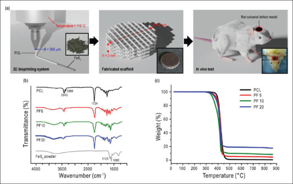
(A) Schematical illustration of this study showing the scaffold fabrication and animal model. (B) FT-IR results and (C) TGA curves for PCL, PF5, PF10, and PF20 scaffolds.
203FT-IR tests were conducted to confirm the incorporation of FeS2 particles in the PCL scaffolds. Figure 1B shows the FT-IR spectra of the scaffolds with the representative peaks. Main peaks of PCL at 2,943, 2,866, and 1,724 cm-1 corresponding to the vibrations of CH2 and C=O, respectively, were observed in all scaffolds[41]. In the case of FeS2, a broad peak ranging from 2,630 to 3,700 cm-1 was observed in iron sulfide containing scaffolds. This is attributed to O-H stretching. Additionally, sharp peaks at 1,123 and 1,080 cm-1 were assigned to FeS2[42].
Moreover, TGA curves in Figure 1C were characterized to confirm the weight fractions of the iron sulfide particles in the PCL scaffolds. The complete decomposition of pure PCL was at about 480°C, but in other scaffolds, residues were observed due to the embedded iron sulfide particles. The residues were approximately 5, 10, and 20%, which were in agreement with the weight fractions of FeS2 in the composite scaffolds. These results confirmed that the iron sulfide particles were well-incorporated in the prepared scaffolds.
3.2. Scaffold characteristics
Figure 2 illustrates the characteristics of the fabricated scaffolds, which include the surface morphology and roughness of the scaffolds. As seen in the optical images in Figure 2A, the FeS2 incorporated scaffolds (PF5, PF10, and PF20) showed a darker color owing to the iron sulfide content. Higher weight fractions of iron sulfide resulted in a darker color. All scaffolds were fabricated to be 8 mm in diameter and 2 mm in height. The strut size and porosity are also listed in Table 2. The geometry of the scaffold is an important factor that influences bone ingrowth in vivo. Pore interconnectivity and a pore size larger than 100 mm are required for bone ingrowth[43]. The interconnected pores act as a passage between the pores to support cellular and vascular penetration, thus favoring bone ingrowth.
Figure 2.

(A) Optical and (b) SEM images of the prepared scaffolds with the corresponding (C) EDS spectra. (D) Surface morphology of the scaffolds taken by AFM.
Table 2. Scaffold characteristics.
| Scaffold | Weight fraction (wt%) | Strut size (mm) | Pore size (mm) | Porosity (%) | |
|---|---|---|---|---|---|
| PCL | FeS2 | ||||
| PCL | 100 | 0 | 295.1 ± 33.4 | 265.7 ± 21.5 | 55.9 ± 1.5 |
| PF5 | 95 | 5 | 294.2 ± 26.8 | 266.7 ± 27.3 | 56.2 ± 2.1 |
| PF10 | 90 | 10 | 292.2 ± 31.7 | 268.6 ± 26.7 | 55.4 ± 1.9 |
| PF20 | 80 | 20 | 293.1 ± 32.7 | 2,667.4 ± 35.2 | 55.6 ± 1.8 |
Abbreviations: PCL, polycaprolactone; FeS2, iron sulfide.
For a closer observation of the scaffolds, SEM and optical microscopy images were evaluated. All scaffolds showed a proper porous structure, as observed in the SEM images. In addition, the particles were observable in the PF5, PF10, and PF20 scaffolds, as seen in the optical microscopy images (Figure 2B). The black dots in the PF scaffolds indicate the embedded FeS2 particles. In contrast, no black dots were visible in the PCL scaffold. The EDS results revealed that the FeS2 incorporated PCL scaffolds were composed of C, O, Fe, and S; however, Fe and S were not detected in the pure PCL scaffold (Figure 2C). The amount of Fe and S increased when the weight fraction of FeS2 in the scaffolds increased. These results demonstrated that FeS2 particles were successfully embedded in the PCL-based scaffolds.
Surface roughness was assessed to evaluate the surface characteristics of the scaffolds. In order to determine the outcome of cell-scaffold interactions, it is necessary to identify the topography of a scaffold surface, including cell morphology, attachment, proliferation, and migration[44-47]. A number of studies have shown the importance of surface roughness in osseointegration in vivo[48]. Figure 2D shows the AFM results. As expected, the addition of FeS2 particles significantly roughened the surface of the scaffolds. Surface roughness was found to be directly dependent on the FeS2 204content. The surface roughness (Ra) values were 2.36-, 4.13-, and 5.77-fold higher for PF5, PF10, and PF20 scaffolds, respectively, compared to that of PCL (Table 3). To date, FeS2 particles have an influence on the surface roughness of PCL scaffolds.
Table 3. Roughness values of the scaffold surfaces.
| PCL | PF5 | PF10 | PF20 | |
|---|---|---|---|---|
| Ra (nm) | 224.1 ± 23.5 | 528.6 ± 41.3 | 925.7 ± 82.6 | 1,293.3 ± 125.5 |
| Rms (nm) | 325.3 ± 36.8 | 613.3 ± 59.40 | 1,103.5 ± 115.4 | 1,471.7 ± 193.3 |
Abbreviations: Ra, roughness average; Rms, root mean square of a surface.
Another important factor in bone tissue engineering is the mechanical properties of the scaffold. The implanted scaffold should be able to withstand stress at the injury site for successful bone formation[49]. Moreover, the mechanical properties of the implanted scaffold strongly affect the adaptive remodeling of the host bone[50]. Figure 3A and B shows the stress–strain curve and the corresponding compressive modulus values, respectively. The incorporation of FeS2 particles significantly enhanced the compressive strength of the scaffolds. The modulus of PF5, PF10, and PF20 increased by 1.89-, 2.47-, and 3.38-fold, respectively, compared to pure PCL (Figure 3B). Moreover, compared to the silica/PCL scaffold (SiP) that was fabricated in our previous study, a 2.3-fold increase was observed when using FeS2 (20 wt%) instead of silica 205particles (20 wt%). The enhancement of the compressive modulus with increasing FeS2 content is visualized in Figure 3C. The strengthening effect was found to be dependent on FeS2 particles. During scaffold compression, the compressive load was endured not only by PCL, but also by FeS2 particles.
Figure 3.

Mechanical properties of the scaffolds, including (A) stress–strain curve and (B) compressive modulus. (C) Schematic showing the interaction during compressive stress.
3.3. In vitro studies
In order to simulate the bone formation process, we used a self-customized cell recruitment model[32]. Figure 4A shows the fluorescence images of the scaffolds after 1, 4, and 10 days of being placed in the cell recruitment model. We observed cell migration toward the scaffold from the surrounding in all groups. As seen in Figure 4B, an increase in cell number was also observed throughout the culture period in all scaffolds. However, a significantly higher number of viable cells were seen on the PF20 scaffold compared to other scaffolds. After 10 days, there were 1.29-, 1.92-, and 2.20-fold greater cells on the PF5, PF10, and PF20 scaffolds, respectively, than those on the control. It appears that the physical environment (mechanical strength and surface roughness) of the PF20 scaffold influenced the migration and proliferation of hMSCs.
Figure 4.

(A) Fluorescence images of 4′,6-diamidino-2-phenylindole (DAPI)-stained scaffolds for cell recruitment study. (B) Quantitative results showing the number of cells on the scaffolds.
3.4. In vivo studies
In order to evaluate the bone formation ability of the FeS2 incorporated scaffolds in vivo, osteogenic potency was analyzed in critical-size calvarial defects in male rats. Figure 5A shows the micro-CT images of the rats after 6 and 12 weeks following scaffold implantation. All animals survived after the surgery, and no evident inflammation or adverse reaction was observed. According to the micro-CT images, there was limited bone formation in the control group, in which PCL scaffold was implanted. However, in the groups implanted with PF scaffolds, the defect sizes decreased to an extent different from the initial size after 20612 weeks. The coronal CT images revealed that the new bone penetrated throughout the whole scaffold in the FeS2 containing groups, while limited bone formation and penetration were seen in the control group. The qualitative evaluations of the micro-CT results are shown in Figure 5B. The bone volume fraction (BV/TV%) of the control, PF5, PF10, and PF20 groups was analyzed, in which the values were 2.4 ± 1.0, 4.0 ± 1.8, 5.2 ± 3.0, and 6.6 ± 2.1% after 6 weeks and 3.3 ± 2.6, 5.4 ± 1.5, 7.2 ± 1.9, and 9.6 ± 1.1% after 12 weeks, respectively. The BV/TV values were significantly greater in the calvarial defect implanted with PF scaffolds than the control. These results indicated that the incorporation of FeS2 particles significantly affected the bone formation in the animal models, wherein a greater amount of FeS2 particles resulted in increased bone formation.
Figure 5.

(A) Representative micro-CT images of newly formed bone after 6 and 12 weeks. (B) Morphometric analysis showing the newly formed bone volume fraction.
For further evaluation, histological assessment was performed using H&E, MT, and IHC staining on the harvested scaffolds. Figure 6A demonstrates the H&E staining results of 6- and 12-week postoperative samples. Active bone formation was observed in all groups, as evident by the continuously growing fibrous tissue in the critical gap. After 6 weeks of implantation, the defect area was predominantly occupied with fibrous tissue. Within the fibrous-like tissue, blood vessels were found in all groups. However, osteoid formation was only observed in the PF10 and PF20 groups, among which only the latter showed evidence of newly formed bone island. Furthermore, multinucleated giant cells and inflammatory cells were recruited near the scaffold area. At 12 weeks post-surgery, newly formed bone tissues were observed at the defect sites of the PF groups. The control group, however, had limited new bone tissue with abundant fibrous tissue. In the PF10 and PF20 groups, osteoblasts and osteocytes were observed in the newly formed bone tissue. Accordingly, an increased FeS2 content resulted in enhanced bone formation. The PF20 group showed a greater number of osteoblasts differentiated from progenitor MSCs. These 207progenitor cells are known to be recruited from the dura mater and the edge of the host bone. An adequate number of cells should be recruited to the defect site for balanced bone formation. In Figure 6B, collagen (blue) and fibrous tissue (red) can be observed in all groups. However, abundant collagen and newly formed bone were observed in the PF groups compared to the control group after 6 and 12 weeks. Among the PF groups, the PF20 group showed the greatest new bone formation. Furthermore, from IHC staining, BMP-2 (yellow) was highly expressed in the PF groups, whereas the control group showed a weak expression of BMP-2. BMP-2 plays an important role in the repair process of bone fractures. As a member of the transforming growth factor-β superfamily, BMP-2 is known to direct MSCs differentiation into osteoblasts[51,52]. The increased BMP-2 expression in the PF20 group led to an upregulated differentiation of MSCs into osteoblasts, which in turn resulted in enhanced bone formation. According to the histologically analyzed results, the groups with PF scaffolds showed greater bone formation, which is in accordance with the micro-CT results. Specifically, the group implanted with scaffold composed of 20 wt% FeS2 had its defect site filled with the largest amount of bone.
Figure 6.

Histological analysis showing representative (A) H&E, (B) MT, and (C) IHC staining images of PCL, PF5, PF10, and PF20 groups at 6 and 12 weeks post-surgery. In the image, the rectangle indicates inflammatory cells; the star indicates osteoid; the black arrow indicates multinucleated giant cells; the blue arrow indicates blood vessel; the green arrow indicates osteocyte; the dotted green line indicates osteoblasts. Abbreviations: NB, new bone; SF, scaffold; FT, fibrous tissue.
In order to visualize the vasculature system in the implanted defect site, micro-CT images were obtained 208after perfusion of vasculature with Microfil (Figure 7A). The development of the vasculature system is one of the pivotal contributors to osteogenesis[53]. Not only are blood vessels needed to provide nutrients and transport waste but also to regulate bone cells such as osteoclasts, osteoblasts, and chondrocytes through angiocrine factor signaling[54]. Blood vessels can penetrate bone scaffolds only when the structure of the scaffolds is composed of interconnected pores. Superior sagittal sinuses with stemmed vessels were observed in all groups after 12 weeks, as seen in the images. This indicates that the pore size and the interconnectivity of the implanted scaffolds provided an adequate environment for vessel penetration. However, an increased number of vessels was observed with greater FeS2 content in the scaffolds. The increased number of blood vessels in the PF20 group may have contributed to the enhanced bone formation.
Figure 7.

(A) Micro-CT images showing Microfil-labeled blood vessels after 12 weeks. (B) Western blot analysis of COL1, OCN, and OPN expression after 2 weeks. Illustration of the bone formation process in this study showing (C) recruitment of progenitor MSCs and vessel formation as well as (D) VEGF/BMP-2 cycle.
The bone formation process is regulated by various genes expressed at different osteoblastic developmental stages. Collagen type 1 (COL1) is an early osteogenic marker that is expressed during the proliferative and maturation stage[55]. Osteocalcin (OCN) and osteopontin (OPN) are late osteogenic markers that are strongly expressed during the mineralization stage[56]. Besides, OCN and OPN have been found to be associated with the mechanical properties of bones[57,58]. Figure 7B shows the relative gene expression results assessed using western blot analysis of the harvested tissues after 2 weeks. As seen in the densitometry data, the PF20 group showed significantly greater expression of OCN and OPN compared to the other groups, where the expression was not significantly different. In the PF20 group, the expression was 2.74- and 1.65-fold greater for OCN and OPN, respectively, compared to that of the control group. In case of COL1, the PF5 (1.88-fold), PF10 (1.73-fold), and PF20 (1.67-fold) groups showed greater expression than the PCL group. However, the expression of COL1 was insignificant between the PF groups. It is noteworthy that the expression of the osteoblast markers was significantly greater in the PF20 groups compared to other groups.
Figure 7C is an overview of the bone formation process in this study. Osteogenesis progresses through the recruitment of progenitor MSCs and neovascularization. It has been documented that MSCs originate from the edge of the damaged host bone and the underlying dura mater. During bone regeneration, the release of several growth factors, including vascular endothelial growth factor (VEGF) and BMP-2, is crucial. VEGF is initially released by the adjacent osteoblasts in the hypoxic environment at the defect site (Figure 7D)[59]. This induces the migration 209and proliferation of endothelial cells, resulting in vessel formation. The new vessels supply nutrients and oxygen essential for the recruitment of progenitor MSCs to induce osteogenesis. Moreover, the differentiation of the recruited osteoprogenitors into osteoblasts relies on BMP-2, which is expressed by endothelial cells. The differentiated cells also secrete angiogenic factors, such as VEGF, to further regulate neovascularization. This cycle progresses throughout the bone formation process. In short, there was an upregulation of new bone formation and neovascularization when FeS2 particles were embedded in PCL scaffolds. Therefore, we assume that the increased compressive modulus due to the incorporation of FeS2 significantly influenced the healing process at the bone defect site.
4. Conclusion
Composite scaffolds composed of PCL and FeS2 particles were developed using a 3D bioprinting system for bone tissue regeneration. The fabricated scaffolds showed enhanced physical and biological properties, depending on the FeS2 content. A significant increase in surface roughness and compressive strength was observed in a dose-dependent manner. Additionally, the in vivo results revealed enhanced neovascularization and bone formation with increasing FeS2 content. Our study demonstrated the potential osteogenic effect of FeS2 for the first time in a rat calvarial defect model. However, hitherto the osteogenic efficacy of FeS2 is still not well-established. Therefore, further studies are required to provide detailed analyses of the efficacy of FeS2 which could advance the field of bone tissue engineering.
Acknowledgments
None.
Funding
This work was supported by the Technology R&D Project through the Korea Health Industry Development Institute (KHIDI) funded by the Ministry of Health & Welfare, Republic of Korea (Grant Number: HI18C0089); the Korea Medical Device Development Fund grant funded by the Korean government (Ministry of Science and ICT, Ministry of Trade, Industry and Energy, Ministry of Health & Welfare, and Ministry of Food and Drug Safety) (Project Number: RS-2022-00140622); and the Ministry of Trade, Industry and Energy (MOITE) and Korea Institute for Advancement of Technology (KIAT) through the International Cooperative R&D Program. (Project Number: P0022310).
Conflict of interest
The authors declare that they have no competing interests.
Author contributions
Project administration: Donggu Kang, Hojun Jeon, SangHyun An
Investigation – animal tests: Yoon Bum Lee, KyungHo Lee, Kil Soo Kim
Investigation – in vitro tests: Eunjeong Choi, Yoonju Nam, Jeong-Seok Lee
Writing – original draft: Donggu Kang, Gi Hoon Yang
Writing – review & editing: Donggu Kang, Gi Hoon Yang
Formal analysis: Gi Hoon Yang, Yoon Bum Lee, Donggu Kang
Visualization: Gi Hoon Yang, Yoon Bum Lee, Donggu Kang
Methodology: MyungGu Yeo, Gil-Sang Yoon
Software: Gi Hoon Yang, Yoon Bum Lee, Donggu Kang
Funding acquisition: Hojun Jeon, SangHyun An, Kil Soo Kim
Ethics approval and consent to participate
This animal study was approved by the local animal ethics committee (approval number: DGMIF-20100801-00).
Consent for publication
Not applicable.
Availability of data
Not applicable.
References
- 1.Boskey AL. Bone composition: Relationship to bone fragility and antiosteoporotic drug effects. Bonekey Rep . 2013;2:447. doi: 10.1038/bonekey.2013.181. [DOI] [PMC free article] [PubMed] [Google Scholar]
- 2.Datta H, Ng W, Walker J, et al. The cell biology of bone metabolism. J Clin Pathol . 2008;61(5):577–587. doi: 10.1136/jcp.2007.048868. [DOI] [PubMed] [Google Scholar]
- 3.Lanyon L. The success and failure of the adaptive response to functional load-bearing in averting bone fracture. Bone . 1992;13:S17–S21. doi: 10.1016/8756-3282(92)90191-x. [DOI] [PubMed] [Google Scholar]
- 4.Phillips A. Overview of the fracture healing cascade. Injury . 2005;36(3):S5–S7. doi: 10.1016/j.injury.2005.07.027. [DOI] [PubMed] [Google Scholar]
- 5.Baker CE, Moore-Lotridge SN, Hysong AA, et al. Bone fracture acute phase response—A unifying theory of fracture repair: Clinical and scientific implications. Clin Rev Bone Miner Metab . 2018;16(4):142–158. doi: 10.1007/s12018-018-9256-x. [DOI] [PMC free article] [PubMed] [Google Scholar]
- 6.Damien CJ, Parsons JR. Bone graft and bone graft substitutes: A review of current technology and applications. J Appl Biomater . 1991;2(3):187–208. doi: 10.1002/jab.770020307. [DOI] [PubMed] [Google Scholar]
- 7.Puelacher W, Vacanti J, Ferraro N, et al. Femoral shaft reconstruction using tissue-engineered growth of bone. Int J Oral Maxillofac Surg . 1996;25(3):223–228. doi: 10.1016/s0901-5027(96)80035-x. [DOI] [PubMed] [Google Scholar]
- 8.LaPrade RF, Botker JC. Donor-site morbidity after osteochondral autograft transfer procedures. Arthrosc J Arthrosc Relat Surg . 2004;20(7):e69–e73. doi: 10.1016/j.arthro.2004.06.022. [DOI] [PubMed] [Google Scholar]
- 9.210Laurencin C, Khan Y, El-Amin SF. Bone graft substitutes. Expert Rev Med Devices . 2006;3(1):49–57. doi: 10.1586/17434440.3.1.49. [DOI] [PubMed] [Google Scholar]
- 10.Vacanti JP, Langer R. Tissue engineering: The design and fabrication of living replacement devices for surgical reconstruction and transplantation. Lancet . 1999;354:S32–S34. doi: 10.1016/s0140-6736(99)90247-7. [DOI] [PubMed] [Google Scholar]
- 11.Chang H-I, Wang Y. In: Regenerative Medicine and Tissue Engineering—Cells and Biomaterials . Eberli D, editor. UK: InTech; 2011. [Google Scholar]
- 12.Bose S, Roy M, Bandyopadhyay A. Recent advances in bone tissue engineering scaffolds. Trends Biotechnol . 2012;30(10):546–554. doi: 10.1016/j.tibtech.2012.07.005. [DOI] [PMC free article] [PubMed] [Google Scholar]
- 13.Saunders RE, Derby B. Inkjet printing biomaterials for tissue engineering: Bioprinting. Int Mater Rev . 2014;59(8):430–448. [Google Scholar]
- 14.Gudapati H, Dey M, Ozbolat I. A comprehensive review on droplet-based bioprinting: Past, present and future. Biomaterials . 2016;102:20–42. doi: 10.1016/j.biomaterials.2016.06.012. [DOI] [PubMed] [Google Scholar]
- 15.Melchels FP, Feijen J, Grijpma DW. A review on stereolithography and its applications in biomedical engineering. Biomaterials . 2010;31(24):6121–6130. doi: 10.1016/j.biomaterials.2010.04.050. [DOI] [PubMed] [Google Scholar]
- 16.Skoog SA, Goering PL, Narayan RJ. Stereolithography in tissue engineering. J Mater Sci Mater Med . 2014;25(3):845–856. doi: 10.1007/s10856-013-5107-y. [DOI] [PubMed] [Google Scholar]
- 17.Ozbolat IT, Hospodiuk M. Current advances and future perspectives in extrusion-based bioprinting. Biomaterials . 2016;76:321–343. doi: 10.1016/j.biomaterials.2015.10.076. [DOI] [PubMed] [Google Scholar]
- 18.Paxton N, Smolan W, Böck T, et al. Proposal to assess printability of bioinks for extrusion-based bioprinting and evaluation of rheological properties governing bioprintability. Biofabrication . 2017;9(4):044107. doi: 10.1088/1758-5090/aa8dd8. [DOI] [PubMed] [Google Scholar]
- 19.Li X, Liu B, Pei B, et al. Inkjet bioprinting of biomaterials. Chem Rev . 2020;120(19):10793–10833. doi: 10.1021/acs.chemrev.0c00008. [DOI] [PubMed] [Google Scholar]
- 20.Ng WL, Lee JM, Zhou M, et al. Vat polymerizationbased bioprinting—Process, materials, applications and regulatory challenges. Biofabrication . 2020;12(2):022001. doi: 10.1088/1758-5090/ab6034. [DOI] [PubMed] [Google Scholar]
- 21.Jiang T, Munguia-Lopez JG, Flores-Torres S, et al. Extrusion bioprinting of soft materials: An emerging technique for biological model fabrication. Appl Phys Rev . 2019;6(1):011310. [Google Scholar]
- 22.Du X, Fu S, Zhu Y. 3D printing of ceramic-based scaffolds for bone tissue engineering: An overview. J Mater Chem B . 2018;6(27):4397–4412. doi: 10.1039/c8tb00677f. [DOI] [PubMed] [Google Scholar]
- 23.Liu X, Ma PX. Polymeric scaffolds for bone tissue engineering. Ann Biomed Eng . 2004;32(3):477–486. doi: 10.1023/b:abme.0000017544.36001.8e. [DOI] [PubMed] [Google Scholar]
- 24.Eivazzadeh‐Keihan R, Bahojb Noruzi E, Khanmohammadi Chenab K, et al. Metal‐based nanoparticles for bone tissue engineering. J Tissue Eng Regen Med . 2020;14(12):1687–1714. doi: 10.1002/term.3131. [DOI] [PubMed] [Google Scholar]
- 25.Porter JR, Ruckh TT, Popat KC. Bone tissue engineering: A review in bone biomimetics and drug delivery strategies. Biotechnol Prog . 2009;25(6):1539–1560. doi: 10.1002/btpr.246. [DOI] [PubMed] [Google Scholar]
- 26.Kikuchi M, Itoh S, Ichinose S, et al. Self-organization mechanism in a bone-like hydroxyapatite/collagen nanocomposite synthesized in vitro and its biological reaction in vivo. Biomaterials . 2001;22(13):1705–1711. doi: 10.1016/s0142-9612(00)00305-7. [DOI] [PubMed] [Google Scholar]
- 27.Rezwan K, Chen Q, Blaker JJ, et al. Biodegradable and bioactive porous polymer/inorganic composite scaffolds for bone tissue engineering. Biomaterials . 2006;27(18):3413–3431. doi: 10.1016/j.biomaterials.2006.01.039. [DOI] [PubMed] [Google Scholar]
- 28.Place ES, George JH, Williams CK, et al. Synthetic polymer scaffolds for tissue engineering. Chem Soc Rev . 2009;38(4):1139–1151. doi: 10.1039/b811392k. [DOI] [PubMed] [Google Scholar]
- 29.Liu D, Nie W, Li D, et al. 3D printed PCL/SrHA scaffold for enhanced bone regeneration. Chem Eng J . 2019;362:269–279. [Google Scholar]
- 30.Cho YS, Quan M, Kang N-U, et al. Strategy for enhancing mechanical properties and bone regeneration of 3D polycaprolactone kagome scaffold: Nano hydroxyapatite composite and its exposure. Eur Polym J . 2020;134:109814. [Google Scholar]
- 31.Zhang Y, Yu W, Ba Z, et al. 3D-printed scaffolds of mesoporous bioglass/gliadin/polycaprolactone ternary composite for enhancement of compressive strength, degradability, cell responses and new bone tissue ingrowth. Int J Nanomed . 2018;13:5433. doi: 10.2147/IJN.S164869. [DOI] [PMC free article] [PubMed] [Google Scholar]
- 32.Yang GH, Yeo M, Choi E, et al. Investigating the physical characteristics and cellular interplay on 3D-printed scaffolds depending on the incorporated silica size for hard tissue regeneration. Mater Des . 2021;207:109866. [Google Scholar]
- 33.Wu Y-HA, Chiu Y-C, Lin Y-H, et al. 3D-printed bioactive calcium silicate/poly-ε-caprolactone bioscaffolds modified with biomimetic extracellular matrices for bone regeneration. Int J Mol Sci . 2019;20(4):942. doi: 10.3390/ijms20040942. [DOI] [PMC free article] [PubMed] [Google Scholar]
- 34.Kim JA, Yun H-s, Choi Y-A, et al. Magnesium phosphate ceramics incorporating a novel indene compound promote osteoblast differentiation in vitro and bone regeneration in vivo. Biomaterials . 2018;157:51–61. doi: 10.1016/j.biomaterials.2017.11.032. [DOI] [PubMed] [Google Scholar]
- 35.Jeon H, Yun S, Choi E, et al. Proliferation and osteogenic differentiation of human mesenchymal stem cells in PCL/silanated silica composite scaffolds for bone tissue regeneration. J Ind Eng Chem . 2019;79:41–51. [Google Scholar]
- 36.Zhou J, Chen K-M, Zhi D-J, et al. Effects of pyrite bioleaching solution of Acidithiobacillus ferrooxidans on viability, differentiation and mineralization potentials of rat osteoblasts. Arch Pharm Res . 2015;38(12):2228–2240. doi: 10.1007/s12272-015-0650-3. [DOI] [PubMed] [Google Scholar]
- 37.Liu L, Zhao G, Gao Q, et al. Changes of mineralogical characteristics and osteoblast activities of raw and processed pyrites. RSC Adv . 2017;7(45):28373–28382. [Google Scholar]
- 38.Zhang L, Zheng Y, Xiong C. Fabrication and characterization of PDLLA/pyrite composite bone scaffold for osteoblast culture. Bull Mater Sci . 2015;38(3):811–816. [Google Scholar]
- 39.Pei Z, Zhang K, Li P, et al. Zi-Ran-Tong loaded brushite bone cement with enhanced osteoblast mineralization ability in vitro. Mater Lett . 2020;259:126908. [Google Scholar]
- 40.211Feng W, Fu W-Y, Zhang Y, et al. Effects of Chinese herb medicine on the biological functions of cultured osteoblasts in vitro. Acad J Shanghai Second Med Univ . 2004;24:542–544. [Google Scholar]
- 41.Chakrapani VY, Gnanamani A, Giridev V, et al. Electrospinning of type I collagen and PCL nanofibers using acetic acid. J Appl Polym Sci . 2012;125(4):3221–3227. [Google Scholar]
- 42.Rath R, Subramanian S, Pradeep T. Surface chemical studies on pyrite in the presence of polysaccharide-based flotation depressants. J Colloid Interface Sci . 2000;229(1):82–91. doi: 10.1006/jcis.2000.6990. [DOI] [PubMed] [Google Scholar]
- 43.Lu J, Flautre B, Anselme K, et al. Role of interconnections in porous bioceramics on bone recolonization in vitro and in vivo. J Mater Sci Mater Med . 1999;10(2):111–120. doi: 10.1023/a:1008973120918. [DOI] [PubMed] [Google Scholar]
- 44.Bettinger CJ, Langer R, Borenstein JT. Engineering substrate topography at the micro‐and nanoscale to control cell function. Angew Chem Int Ed . 2009;48(30):5406–5415. doi: 10.1002/anie.200805179. [DOI] [PMC free article] [PubMed] [Google Scholar]
- 45.Loesberg W, Te Riet J, Van Delft F, et al. The threshold at which substrate nanogroove dimensions may influence fibroblast alignment and adhesion. Biomaterials . 2007;28(27):3944–3951. doi: 10.1016/j.biomaterials.2007.05.030. [DOI] [PubMed] [Google Scholar]
- 46.Ivirico JE, Salmeron‐Sanchez M, Ribelles JG, et al. Proliferation and differentiation of goat bone marrow stromal cells in 3D scaffolds with tunable hydrophilicity. J Biomed Mater Res Part B Appl Biomater . 2009;91(1):277–286. doi: 10.1002/jbm.b.31400. [DOI] [PubMed] [Google Scholar]
- 47.Jansen EJ, Sladek RE, Bahar H, et al. Hydrophobicity as a design criterion for polymer scaffolds in bone tissue engineering. Biomaterials . 2005;26(21):4423–4431. doi: 10.1016/j.biomaterials.2004.11.011. [DOI] [PubMed] [Google Scholar]
- 48.Deng Y, Liu X, Xu A, et al. Effect of surface roughness on osteogenesis in vitro and osseointegration in vivo of carbon fiber-reinforced polyetheretherketone–nanohydroxyapatite composite. Int J Nanomed . 2015;10:1425. doi: 10.2147/IJN.S75557. [DOI] [PMC free article] [PubMed] [Google Scholar]
- 49.Salgado AJ, Coutinho OP, Reis RL. Bone tissue engineering: state of the art and future trends. Macromol Biosci . 2004;4(8):743–765. doi: 10.1002/mabi.200400026. [DOI] [PubMed] [Google Scholar]
- 50.Spector M. Anorganic bovine bone and ceramic analogs of bone mineral as implants to facilitate bone regeneration. Clin Plast Surg . 1994;21(3):437–444. [PubMed] [Google Scholar]
- 51.Li C, Vepari C, Jin H-J, et al. Electrospun silk-BMP-2 scaffolds for bone tissue engineering. Biomaterials . 2006;27(16):3115–3124. doi: 10.1016/j.biomaterials.2006.01.022. [DOI] [PubMed] [Google Scholar]
- 52.Riley EH, Lane JM, Urist MR, et al. Bone morphogenetic protein-2: Biology and applications. Clin Orthop Relat Res . 1996;324:39–46. [PubMed] [Google Scholar]
- 53.Kanczler J, Oreffo R. Osteogenesis and angiogenesis: The potential for engineering bone. Eur Cells Mater . 2008;15(2):100–114. doi: 10.22203/ecm.v015a08. [DOI] [PubMed] [Google Scholar]
- 54.Zhu S, Bennett S, Kuek V, et al. Endothelial cells produce angiocrine factors to regulate bone and cartilage via versatile mechanisms. Theranostics . 2020;10(13):5957. doi: 10.7150/thno.45422. [DOI] [PMC free article] [PubMed] [Google Scholar]
- 55.Köllmer M, Buhrman JS, Zhang Y, et al. Markers are shared between adipogenic and osteogenic differentiated mesenchymal stem cells. J Dev Biol Tissue Eng . 2013;5(2):18. doi: 10.5897/JDBTE2013.0065. [DOI] [PMC free article] [PubMed] [Google Scholar]
- 56.Franceschi R. The developmental control of osteoblastspecific gene expression: Role of specific transcription factors and the extracellular matrix environment. Crit Rev Oral Biol Med . 1999;10(1):40–57. doi: 10.1177/10454411990100010201. [DOI] [PubMed] [Google Scholar]
- 57.Thurner PJ, Chen CG, Ionova-Martin S, et al. Osteopontin deficiency increases bone fragility but preserves bone mass. Bone . 2010;46(6):1564–1573. doi: 10.1016/j.bone.2010.02.014. [DOI] [PMC free article] [PubMed] [Google Scholar]
- 58.Poundarik AA, Diab T, Sroga GE, et al. Dilatational band formation in bone. Proc Natl Acad Sci . 2012;109(47):19178–19183. doi: 10.1073/pnas.1201513109. [DOI] [PMC free article] [PubMed] [Google Scholar]
- 59.Wang Y, Wan C, Deng L, et al. The hypoxia-inducible factor α pathway couples angiogenesis to osteogenesis during skeletal development. J Clin Investig . 2007;117(6):1616–1626. doi: 10.1172/JCI31581. [DOI] [PMC free article] [PubMed] [Google Scholar]
Associated Data
This section collects any data citations, data availability statements, or supplementary materials included in this article.
Data Availability Statement
Not applicable.