

Abstract
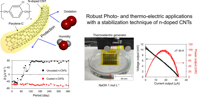
Stabilization techniques for n-doped carbon nanotubes (CNTs) are essential for the practical use of CNT devices. However, none of the reported n-dopants have sufficient robustness in a practical environment. Herein, we report a highly stable technique for fabricating n-doped CNT films. We elucidate the mechanism by which air stability can be achieved by completely covering CNTs with n-dopants to prevent oxidation; consequently, the stability is lost when exposed to scratches or moisture. Therefore, we introduce parylene as a protective layer for n-doped CNTs and achieve air stability for more than 365 d. Moreover, we demonstrate outstanding robust thermo-electric power generation from strong acids, alkalis, and alcohols, which cannot be realized with conventional air-stable n-dopants. The proposed stabilization technique is versatile and can be applied to various n-dopants. Thus, it is expected to be a key technology in the practical application of CNT devices.
Keywords: n-doped carbon nanotube films, air stability, stabilization technique, parylene coating, thermo-electric power generation
1. Introduction
Since their discovery in 1991 by Iijima,1 carbon nanotubes (CNTs) have attracted attention as promising materials beyond conventional solid-state materials and have been extensively studied in a variety of fields.2−5 The advantageous features of CNTs, which are one-dimensional nanostructures composed of carbon, are characterized by superior physical properties, such as electrical conductivity6 and thermo-electric power,7 broadband absorption spectra from near-infrared (NIR) to terahertz (THz) frequency range based on plasmon resonance in the length/diameter directions of CNTs,8−10 high robustness,11 and flexibility.12−14 These advantages have enabled the development of various applications and research on transistors,15,16 motion sensors,17,18 terahertz sensors,19,20 biosensors,21,22 thermo-electric generators,23,24 triboelectric generators,25,26 optical filters,27,28 and reinforced composites.29,30 As an example of the device mechanism, photo-thermo-electric devices, including thermo-electric generators and photothermal sensors, are primarily based on the Seebeck effect, which is expressed as ΔV = S × ΔT, where S denotes the Seebeck coefficient and ΔT indicates the temperature gradient.19 Therefore, improving the Seebeck coefficient of CNTs is a fundamental strategy for improving the performance of these photo-thermo-electric devices. The physical properties of CNTs are governed by their Fermi level; for instance, the Seebeck coefficient of CNTs can be changed from positive (p-type) to negative (n-type),31 and the NIR–THz absorbance (the plasmon resonance) can be tuned along with Fermi-level control using field-effect techniques.32 Meanwhile, chemical dopants are applied as a powerful technique for the Fermi-level control of CNT structures, such as fibers and films. Most chemical molecules adsorb onto CNTs via van der Waals interactions based on the π–π interaction, and charge carriers are injected into the CNTs based on the π-electron system. Hole (p-type) or electron (n-type) injection can be controlled by the molecular structure. To enhance the performance of photo-thermo-electric devices, p–n junctions are typically utilized to increase the alternative Seebeck coefficient of materials; therefore, as a pristine state under air conditions, n-dopants for p-CNTs are particularly important and have been developed in various methods, such as polyethyleneimine,33 nitrogen-containing molecules,34,35 amidine-based molecules,36 imidazolium salts,37−39 and supramolecular complexes.40,41 However, the critical problem of the n-doped stability in air remains because the CNTs gradually accept holes from oxygen molecules (oxidations) in air and are dedoped to p-type in several days up to months. Furthermore, although the features of these dopants, which are soluble in water and alcohol, make it easy to fabricate devices, they have the disadvantage of impeding the wearable and outdoor use of CNT devices. Previously, we reported CNT-based NIR–THz sensors and related photo-thermo-electric sensing applications.8,19,32,42−47 However, the air stability of the sensor has not been discussed thus far. In fact, our sensor malfunctioned after operating for several months under air conditions. The problem limits the practical use of CNT devices. Therefore, it is essential to develop a technology for stabilizing n-doped CNTs on a yearly basis in air conditions and additionally against physical/chemical stimuli, such as physical contact, scratching, sweating, and rain.
Herein, we report a stabilizing technique for n-doped CNTs. We clarify the factors that control stability and deterioration by investigating the transient thermo-electric properties. Based on these findings, we employed parylene coating technology to enhance the stability of the macroscopic device and achieve stabilization of n-doped CNTs for more than 1 year under atmospheric conditions. Furthermore, by utilizing the high physical and chemical resistance of parylene, we demonstrate thermo-electric power generation from a strongly alkaline solution of sodium hydroxide (NaOH). These ultra-robust n-doped CNTs far exceed the stability of conventional n-doped CNTs (several months under air conditions) and thus are expected to be widely employed in thermo-electric devices, wearable devices, and photothermal sensors.
2. Results
2.1. Investigation of Transient Thermo-Electric Properties of n-Doped CNTs
Although there are several reports on n-dopants, their stabilization and degradation mechanisms have not been elucidated in detail.33−41 Therefore, we aim to clarify the factor that governs n-dopant degradation by measuring the transient response of the thermo-electric properties of n-doped CNTs under various conditions. Figure 1 depicts the fundamental properties of the n-doped CNTs used in this experiment. We utilized supramolecular complexes made from benzo-18-crown-6 ether (B18C6) and potassium hydroxide (KOH) solution as n-dopants.40 In the solution, K+ cations were captured by the cavities of the B18C6 to form the inclusion complexes of [K-B18C6]+OH–. For [K-B18C6]+OH–, OH– is highly activated as the “naked anion”, which could promote the electron injection to the CNTs ideally as follows:
| 1 |
Figure 1.

Basic properties of n-doped CNTs. (a) Formation methods and n-doping of CNTs. CNTs and devices were formed via the mask-through filtration method and then immersed into the n-dopant solution of the B18C6 complex. (b) Photographic image of n-doped CNTs. (c) Height profile of the n-dopant, where the sampling line is indicated by the blue line in (b). (d) Thickness versus concentration of the n-dopant. (e) Schematics of the homemade thermoelectric property measurement system. (f) Doping characteristics of n-doped CNTs. The Seebeck coefficient of the pristine CNTs changed from positive (55 μV K–1) to negative (−50 μV K–1) with increasing concentration of n-dopants.
We expect that the B18C6 complex absorbed onto the surface of the CNTs stabilizes the transferred electrons, as illustrated in Figure 1a. The single-walled CNT film was filtered and transferred onto a polyimide film. Following that, by immersing the CNTs in an n-dopant solution, the benzocrown ether complex adsorbs and injects electrons into the CNTs (n-doping) (see Section 4 for more details). Figure 1b, the photograph of the interface between the pristine and n-doped CNTs, clearly shows that the n-doped CNTs are covered with the benzocrown ether complex. The thickness of the benzocrown ether complex is proportional to the concentration of the dopant solution (Figure 1c,d). Figure 1f illustrates the results of the Seebeck coefficient of CNTs immediately after n-doping measured using the homemade thermo-electric property measurement system depicted in Figure 1e. It can be observed that the Seebeck coefficient decreases as the dopant thickness (dopant concentration) increases and saturates at −60 μV K–1 when the dopant concentration exceeds 0.05 mol L–1. This is a general feature of chemical doping, which differs from field-effect techniques, which indicates that doping cannot exceed the electron injection capability derived from the structure of the dopant.
Subsequently, we stored the n-doped CNTs with different dopant concentrations in air and measured the transient response of the thermo-electric properties. Figure 2a–c indicates the transient response of the Seebeck coefficient S, electrical conductivity σ, and power factor PF of CNTs that are doped with a dopant concentration of 0.01 mol L–1. When doping with a low dopant concentration (0.01 mol L–1), it was found that electron dedoping started immediately after doping and returned to the original p-type after 60 min. This dedoping behavior was simultaneously observed for the Seebeck coefficient, electrical conductivity, and power factor. Figure 2d illustrates the transient response of the Seebeck coefficient with the variation of the dopant concentration from 0 to 0.5 mol L–1. The result clearly shows that the dopant lifetime increases as the dopant concentration increases, and it can be observed that the n-doped CNTs with a dopant concentration of 0.5 mol L–1 are stable in air conditions for more than 250 days. To clarify the mechanism of the stability improvement by increasing the dopant concentration, we conducted two durability tests: mechanical stimulation and humidity. For the former, we prepared two heavily n-doped CNTs of 0.5 and 1.0 mol L–1 and observed the transient response of the Seebeck coefficient. As shown in Figure 2d, the heavily n-doped CNTs were stable even when stored in air. Subsequently, we applied mechanical strain only on the CNTs doped with 1.0 mol L–1 on day 150 to crack the dopants adsorbed onto the CNTs (Figure 2e inset). Consequently, it was found that only the cracked n-doped CNTs experienced gradual electron dedoping after day 150 (cracked day). This is an interesting result, suggesting that the coating quality of n-dopants is more significant than the total amount of n-dopants (dopant concentration) for the stabilization of n-doping. For the latter, we prepared CNTs doped at the same concentration (0.15 mol L–1) and observed the transient response of the Seebeck coefficient when stored under humidity-controlled air (Figure 2f). The results clearly reveal that the CNTs stored at 5% humidity retained the n-type for over a year, whereas those stored at 75% humidity were gradually dedoped with electrons and returned to the pristine p-type after one year. Conventionally, atmospheric oxygen is considered the dominant cause of dedoping. However, this result clearly shows that humidity, apart from oxygen, directly affects the deterioration of n-doped CNTs, and it is a result that has never been reported before. We speculate that the deliquescence of the n-dopant is the mechanism of deterioration owing to humidity. As the n-dopant of the B18C6 complex is hydrophilic, it absorbs moisture and deliquesces. It is considered that the cation (K+ in this case) that had been captured by B18C6 was detached, and consequently, the electron stabilization ability was gradually lost. Another reason is that the molecular structure of the B18C6 complex was destroyed by hydrolysis in an oxygen/light atmosphere, similar to the underlying mechanism of the irreversible degradation of adhesives with water.48,49 However, although we measured the transient response of the IR spectrum for months (see Supporting Information), clear evidence has not yet been obtained.
Figure 2.

Transient thermoelectric properties of n-doped CNTs. (a–c) Transient Seebeck coefficient, electrical conductivity, and power factor of the n-doped CNTs with a concentration of 0.01 mol L–1, respectively. (d) Transient Seebeck coefficient of the n-doped CNTs with a concentration of 0.01–0.5 mol L–1. The lifetime of n-doped CNTs increases as the n-dopant concentration increases (from 60 min @ 0.01 mol L–1 to >250 days @ 0.5 mol L–1). (e) Durability test against mechanical strains. Mechanical strains were only applied on the CNTs doped with 1.0 mol L–1 on day 150 to crack the dopants adsorbed to the CNTs (inset). Consequently, only the cracked n-doped CNTs exhibited electron dedoping after day 150 (the cracked day). (f) Durability test against humidity. (g) Conceptual illustration of the deterioration of n-doped CNTs. Long-term air stabilization of the n-doped CNTs is achieved by the n-dopant completely covering the CNTs and preventing oxidation. However, electron dedoping occurs (N-dopant degradation) when the n-dopant layer degrades owing to mechanical friction or moisture.
Based on the above findings, we conclude the stabilizing mechanism that n-dopants play a dual role in CNTs doping: they inject electrons into CNTs and protect them from oxidation. Therefore, increasing the dopant concentration and forming a thick dopant layer are crucial for achieving long-term stabilization. However, the dopant is just a type of salt and is fragile, so the electron stabilization ability is easily lost by physical/chemical stimuli, causing the deterioration of n-CNTs (Figure 2g).
2.2. Parylene Coating for High Air Stability
According to the findings from the previous section, to improve the stability of n-type CNTs, the development of mechanically durable hydrophobic n-dopants is a problem in microscale science research. From a macroscale perspective, another approach is to utilize a protection layer, that is, the n-dopants only play the role of injecting electrons into the CNT and protect the n-doped CNTs with another highly durable material. Therefore, we used a protective layer of poly(chloro-p-xylylene) (parylene-C). Parylene is well known as a polymer with high physical/chemical resistance, flexibility, and biological conformity. Owing to such characteristics, it is used as a protective layer in transistors, thermo-electric generators, and flexible devices.50−55 However, the n-doping stabilization mechanism where n-dopants function as a protection layer has not been clarified thus far. Furthermore, the use of a parylene coating to improve the air stability of n-dopants has not been reported, and the effect remains unclear. Therefore, in this study, we investigated whether the introduction of a parylene coating as the protective layer of the n-dopants can improve the air stability of n-doped CNTs. Figure 3 illustrates the concept of parylene-coated n-doped CNTs. Initially, the CNTs were doped with the n-dopant of the B18C6 complex, and then, the protection layer of the parylene was deposited on the n-doped CNTs using a CVD process. In the deposition process, because parylene is applied as a gas, it penetrates the CNT network and provides complete encapsulation of the CNTs. Scanning electron microscopy images clearly show that the CNT bundle size increased with parylene deposition, and the CNTs were fully encapsulated with a parylene thickness of 100 nm (Figure 3b–e).
Figure 3.

Parylene coating for high air stability. (a) Conceptual image of the parylene coating. (b–e) SEM images of n-doped CNTs with parylene coating thicknesses of 0, 5, 10, and 100 nm, respectively. When the coating thickness is 100 mm, the CNTs is completely covered with the parylene, and no CNTs including the bundle are observed. Instead, parylene crystal growth is observed.
Figure 4 illustrates the transient response of the physical properties of the parylene-coated n-doped CNTs stored under air conditions, where the dopant concentration was 0.1 mol L–1. Without the parylene coating, the n-dopants gradually degrade under the influence of oxygen and moisture, similar to Figure 2b, returning to the pristine p-CNTs after approximately 120 days. In contrast, the parylene-coated n-doped CNTs exhibited high air stability, and the Seebeck coefficient did not change even after a year. This result clearly reveals that protecting the n-dopants with parylene from external stimuli significantly improves air stability. Regarding the relationship between coating thickness and stability, there was no difference in the Seebeck coefficient. However, when the resistivity, which is more sensitive to the Fermi-level fluctuations, is measured, we can observe that the thicker 10 μm-coated CNTs exhibit less fluctuation than that of the 100 nm-coated CNTs. The increase in resistivity correlates with humidity fluctuations at the measurement location (Saga, Japan, Figure 4c,d) and is therefore the effect of moisture adsorption on parylene. Because the n-dopants were not degraded in this case, the resistance fluctuation is a reversible reaction that increases/decreases in conjunction with humidity at the measurement location. We note that since the adsorption/desorption of moisture to/from the parylene coating is a very slow reaction compared to atmospheric humidity changes, there is a delay between humidity and resistance changes. To investigate the effect of this moisture absorption, two types of parylene (parylene-C and parylene-N, as sketched in Figure 4e), which have different water vapor transmission rates (WVTRs), were used to compare the air stability, where the WVTR of the parylene-C and parylene-N are 0.08 and 0.59 g mm m–2 day–1, respectively.56 We prepared parylene-C/parylene-N coated n-doped CNTs with the same dopant concentration (0.1 mol L–1) and a coating thickness of 500 nm and compared the transient response of the thermo-electric properties. Figure 4f,g illustrates that high n-type stabilization of more than one year can be achieved with both parylene coatings. In other words, no clear difference was observed between them during the one-year measurements. This result indicates that the introduction of the protection layer on n-dopants dramatically improves the air stability, and it was found that the difference in the WVTR does not affect the stability if the layer is sufficiently thick.
Figure 4.

Transient thermoelectric properties of parylene-coated n-doped CNTs. (a) Transient Seebeck coefficient of n-doped CNTs with/without parylene coating. Unlike uncoated CNTs (black dots), the negative Seebeck coefficient of the coated CNTs remained stable for over a year. (b) Transient resistivity of parylene-coated n-doped CNTs. (c) Humidity at the experimental location (Saga, Japan) during the measurement period. The resistivity reversely increases/decreases in conjunction with the humidity of the measurement location. (d) Humidity dependence of the changes in the resistance. (e) Molecule structures of parylene-C and parylene-N. (f–g) Comparison between the Seebeck coefficient and resistivity of n-doped CNTs with parylene-C/parylene-N coating.
2.3. Outstanding Robust Thermo-Electric Applications
As shown in Figure 2d, it was reported that simply increasing the n-dopant concentration can stabilize the n-type for a long time in the air. The advantage of utilizing parylene coatings is their overwhelming robustness to physical and chemical stimuli. Figure 5a illustrates the chemical durability of the n-doped CNTs. We immersed the n-doped CNTs in a variety of solutions, such as water (H2O), KOH, sulfuric acid (H2SO4), ethanol, and acetone for 7 days. The experimental results indicate that when the uncoated n-doped CNTs are immersed in water or alcohol, they return to p-CNTs with a positive Seebeck coefficient owing to the desorption of the n-dopants. Additionally, when immersed in a strong acid or alkaline solution, the polyimide of the substrate was dissolved, and the device was broken. The general response is that the n-dopant is a chemical material that dissolves in chemical solvents, making n-doped CNTs fragile. Parylene, on the other hand, is a polymer that is highly resistant to physical and chemical stimuli and is used as a protective film for semiconductor devices.50−55 Therefore, in the case of parylene-coated n-doped CNTs, the thermo-electric properties did not change even after immersion in strong acid, strong alkali, and alcohol for 7 d (Figure 5b). Utilizing the durability of this parylene coating, we fabricated an ultra-robust thermo-electric generator and demonstrated thermo-electric generation from a strongly alkaline solution (Figure 5c–e). This is a thermo-electric application in a high-load environment that cannot be conceived for thermo-electric generators using conventional n-dopants.
Figure 5.

Robust thermo-electric applications. (a) Photographic image and (b) results of the chemical durability test of n-doped CNTs. Compared with the uncoated n-doped CNTs that returned to p-type following 7 days of immersion, the Seebeck coefficient of the parylene-coated n-doped CNTs still remains n-type even after being immersed in strong acid, strong alkali, and alcohol. (c) Photographic image of the robust thermoelectric application (thermo-electric power generation from strong alkali solution). (d) Voltage output versus the temperature gradient. (e) Power output characteristics with a temperature gradient of 60 K.
2.4. Trade-off between the Robustness and Performance of Photo-Thermo-Electric Applications
Similar to thermo-electric applications, it is possible to improve the robustness of photo-thermo-electric applications by introducing a parylene coating. We measured the air stability of the broadband photosensors based on the detection mechanism of the photo-thermo-electric effect.19,44 The half area of the p-CNTs was n-doped by the B18C6 complex with a concentration of 0.1 mol L–1, and the photo-thermo-electric voltage generated by the IR irradiation at the p–n junction was measured using a multimeter (Figure 6a). Figure 6b illustrates the air stability of the photo-thermo-electric sensor. The response of the uncoated sensor decreased to zero after 120 d. The result indicates that the thermal properties of the CNTs reverted from n-type to p-type after 120 d, which is in good agreement with the n-dopant lifetime depicted in Figure 4a. In contrast, the response of the parylene-coated sensors remained the same after 180 d, indicating that the coating technique is useful for enhancing the durability of sensors, similar to thermo-electric applications. However, for photo-thermo-electric applications, the parylene coating deteriorated the sensing performance. In the case of photo-thermo-electric sensors that use light as a heat source, the heat capacity of the sensor governs the amount and speed of heat generation;8 in other words, the sensitivity and time constant of the sensor. Coating the sensor with parylene increased the total heat capacity of the sensor, which degraded the sensitivity and time constant. To quantitatively evaluate the performance degradation owing to the parylene coating, we performed heat transfer analysis using the finite element method8 (Figure 6c,d). Figure 6e–g presents a comparison between the simulation and experiment of the sensing performance. The experimental results are consistent with the simulations that the sensitivity of the sensor deteriorates by approximately 5% when the parylene is coated with 10 μm, which is smaller than the individual variation (10%) between the sensors and has a negligible effect. However, the adverse effect on the time constant is large, and it was found that the 10-μm coating deteriorates the time constant from 180 to 600 ms, which is approximately 3.5 times slower. Accordingly, the sensor robustness and performance are in a trade-off relationship; thus, instead of simply applying a thick layer of parylene, it is essential to select the optimum coating thickness based on the actual usage environment.
Figure 6.

Photo-thermo-electric response of the parylene-coated sensors. (a) Photograph of the photo-thermo-electric sensors. IR waves were irradiated at the p–n junction, and the generated voltage was measured. (b) Air-stability of the parylene-coated sensors. The response of uncoated sensor decreases to zero after 120 days; however, the response of the parylene-coated sensors remains the same after 180 days. (c) Models and (d) thermal distribution example of the thermal conduction analysis. (e) Response, (f) time constant, and (g) transient response of the parylene-coated sensors. As the coating thickness increases, the sensitivity and time constant of the sensor deteriorate.
3. Discussion
In this study, we clarified the deterioration mechanism of n-doped CNTs and developed a stabilization technique for use in photo-thermo-electric applications. The condition for stabilizing n-doped CNTs aims to prevent the contact of CNTs with oxygen, and the air stability can be improved by completely covering CNTs with n-dopants. However, because n-dopants are generally fragile salts, they are degraded by deliquescence owing to moisture and physical scratches, causing instability in n-doped CNTs. The result suggests that long-term n-type stabilization under air can be achieved with hydrophobic n-dopants, and such microscopic chemical research is desirable for the development of CNT research. From a macroscopic perspective, we developed a stabilizing technique that introduces parylene as a protective layer. In other words, the n-dopant and parylene play the roles of injecting electrons and preventing oxidation, respectively. Consequently, the parylene coating technique has proven to be extremely useful, achieving not only n-doped stabilization in air for more than a year but also durability to physical/chemical stimuli. Using this coating technique, we demonstrated robust thermo-electric generation from strong alkaline solutions, which was impossible with the stability of conventional n-type dopants. Moreover, we analyzed the effect of the parylene coating using the finite element method and clarified the trade-off between robustness and performance in photo-thermo-electric applications. At this point, the following aspects still remain: (a) the microscopic mechanism of how the B18C6 complex deteriorates owing to moisture, and (b) the mechanism by which even n-doped CNTs completely coated with parylene reversibly change their conductivity in conjunction with external humidity. Therefore, the change in the molecular structure should be investigated via spectral analysis methods, such as Fourier-transform infrared spectroscopy and X-ray electron spectroscopy, in future studies.
The stabilization of n-dopants is crucial for the practical implementation of devices, and various chemical dopants have been studied. Our results obtained using the parylene coating are applicable to various n-dopants. The versatile stabilization technology considerably improves the physical/chemical durability. It can be utilized for various applications, such as wearable biological monitoring, thermo-electric power generation from industrial strong acid/alkaline wastewater, and long-term non-destructive inspection using NIR–THz waves. Thus, we expect that this study will have a significant impact on CNT research, and the technique can be used in the practical applications of CNT devices.
4. Methods
4.1. Materials
We used a super-growth single-walled metallic-semiconducting mixed CNT dispersion (ZEON Corporation). Generally, the electrical conductivity and Seebeck coefficient are 500 S cm–1 and 60 μV K–1 (pristine)/–60 μV K–1 (n-doped), respectively. The n-dopant B18C6 was purchased from Tokyo Chemical Industry Co., Ltd. The concentrations of B18C6 and KOH complexes were adjusted by adding pure water. Parylene-C and parylene-N were purchased from Specialty Coating Systems Inc.
4.2. CNT Fabrication
CNTs and devices (Figures 2, 4, 5c, and 6a) were fabricated via the mask-through filtration method (see the Supporting Information for details). The 5-μm thickness polyimide was processed using the laser ablation method. The laser-patterned polyimide mask was attached to a polyvinylidene difluoride membrane filter (thickness: 125 μm; pore size: 0.1 μm), and the CNT dispersion was filtered through them. The CNTs were selectively filtered through the mask pattern and formed on a membrane filter with the desired shape. After drying, the CNTs were transferred to a polyimide film (thickness: 12.5 μm). The thickness of the CNTs could be controlled by varying the filtration amount of the CNT dispersion. The dimensions of the CNTs for each device were as follows: 500 × 3000 × 3 μm for thermal property measurement (Figures 2 and 4), 1000 × 30,000 × 3 μm, and eight elements for the thermo-electric generator (Figure 5c), and 500 × 8000 × 3 μm for the photo-thermo-electric sensor (Figure 6b).
4.3. Measurement Systems
The height profiles of the CNTs and n-dopants were measured by confocal laser microscopy (VK-X1000/1050, Keyence Corporation). The Seebeck coefficient of the CNTs was measured using a homemade thermo-electric property measurement system (Figure 1e). The CNTs were placed between a heater and cooler, and a pair of chromel–alumel thermocouples was placed on both sides of the CNTs. The voltages V1 between the chromel electrodes and V2 between the alumel electrodes were measured using a multimeter. In this situation, V1 and V2 can be expressed as follows:
| 2 |
| 3 |
where SCNT, SChromel, and SAlumel represent the Seebeck coefficients of CNTs, chromel, and alumel, respectively. From eqs 2 and 3, SCNT can be derived as follows:
| 4 |
The humidity of the air (Figure 2f) was controlled using a desiccator (5%) and saturated salt solution of sodium chloride (75%).57 Parylene was deposited using an SCS Labcoter 2 PDS 2010 (Specialty Coating Systems, Inc.). For the photo-thermo-electric sensors (Figure 6), an IR LED (L14336-0083R, Hamamatsu Photonics K.K., wavelength of 830 nm, and power of 1 mW) was used. The IR wave was collimated and focused by lenses on the p–n junction of the CNTs, and the generated voltage was measured using a multimeter.
4.4. Thermal Conductivity Analysis
The thermal distribution and transient thermal response of the photo-thermo-electric sensors (Figure 6c–g) were analyzed via the finite element method using ANSYS Mechanical software (Cybernet Systems Co., Ltd.). Thermal conduction was calculated based on the solution of the following heat equation:
| 5 |
where ρ symbolizes the density, c indicates the specific heat capacity, k represents the thermal conductivity, and Q denotes the total amount of heat applied.8 We assumed that the IR absorption rate was 100% and that heat was applied directly to the p–n junction of the CNTs. The physical parameters of materials employed in the simulation were as follows: the density, specific heat capacity, and thermal conductivities of the CNTs, lead wires, polyimide film, and parylene-C were 0.6 g cm–3, 0.66 J g–1 K–1, 10 W m–1 K–1 for the X-Y plane and 0.1 W m–1 K–1 for the Z-plane; 7.85 g cm–3, 0.434 J g–1 K–1, 60.5 W m–1 K–1; 1.4 g cm–3, 1.13 J g–1 K–1, 0.3 W m–1 K–1; and 1.289 g cm–3, 0.712 J g–1 K–1, 0.084 W m–1 K–1, respectively. The Seebeck coefficient of p – type (n – type) CNTs were 40(−40) μV K–1, and the heat transfer coefficient of air was 4.65 W m–2 K–1 at 300 K.
Acknowledgments
This work was supported by JSPS KAKENHI (Grant No. JP21K14501), JST ACT-X (Grant No. JPMJAX21K8), and JST FOREST (Grant No. JPMJFR2128); the TEPCO Memorial Foundation; the Murata Science Foundation; and the Iketani Science and Technology Foundation.
Supporting Information Available
The Supporting Information is available free of charge at https://pubs.acs.org/doi/10.1021/acsami.2c21347.
Additional experimental procedures including the CNT formation and the IR spectrum of n-doped CNTs; CNTs selectively filtrated through the laser-patterned polyimide mask; and transient IR spectrum of n-doped CNTs after 120 days in humidity of 95%, 298 K measured (PDF)
Author Contributions
D.S. proposed the idea, designed the experiment, fabricated the device, analyzed and measured the device performance, and wrote the manuscript. Y.N. and K.S. discussed the chemical characteristics of the dopant deterioration. N.T. supervised the study.
The authors declare no competing financial interest.
Notes
The authors declare that all data that support the findings of this study are available within the article and its Supporting Information files. The data that support the findings of this study are available from the corresponding author upon reasonable request.
Supplementary Material
References
- Iijima S. Helical Microtubules of Graphitic Carbon. Nature 1991, 354, 56–58. 10.1038/354056a0. [DOI] [Google Scholar]
- Kataura H.; Kumazawa Y.; Maniwa Y.; Umezu I.; Suzuki S.; Ohtsuka Y.; Achiba Y. Optical Properties of Single-Wall Carbon Nanotubes. Synth. Met. 1999, 103, 2555–2558. 10.1016/S0379-6779(98)00278-1. [DOI] [Google Scholar]
- Journet C.; Maser W. K.; Bernier P.; Loiseau A.; Lamy de la Chapelle M.; Lefrant S.; Deniard P.; Lee R.; Fischer J. E. Large-Scale Production of Single-Walled Carbon Nanotubes by the Electric-Arc Technique. Nature 1997, 388, 756–758. 10.1038/41972. [DOI] [Google Scholar]
- Hata K.; Futaba D. N.; Mizuno K.; Namai T.; Yumura M.; Iijima S. Water-Assisted Highly Efficient Synthesis of Impurity-Free Single-Walled Carbon Nanotubes. Science 2004, 306, 1362–1364. 10.1126/science.1104962. [DOI] [PubMed] [Google Scholar]
- Yang F.; Wang X.; Zhang D.; Yang J.; Luo D.; Xu Z.; Wei J.; Wang J. Q.; Xu Z.; Peng F.; Li X.; Li R.; Li Y.; Li M.; Bai X.; Ding F.; Li Y. Chirality-Specific Growth of Single-Walled Carbon Nanotubes on Solid Alloy Catalysts. Nature 2014, 510, 522–524. 10.1038/nature13434. [DOI] [PubMed] [Google Scholar]
- Ebbesen T. W.; Lezec H. J.; Hiura H.; Bennett J. W.; Ghaemi H. F.; Thio T. Electrical Conductivity of Individual Carbon Nanotubes. Nature 1996, 382, 54–56. 10.1038/382054a0. [DOI] [Google Scholar]
- Nakai Y.; Honda K.; Yanagi K.; Kataura H.; Kato T.; Yamamoto T.; Maniwa Y. Giant Seebeck Coefficient in Semiconducting Single-Wall Carbon Nanotube Film. Appl. Phys. Express 2014, 7, 025103 10.7567/APEX.7.025103. [DOI] [Google Scholar]
- Suzuki D.; Ochiai Y.; Kawano Y. Thermal Device Design for a Carbon Nanotube Terahertz Camera. ACS Omega 2018, 3, 3540–3547. 10.1021/acsomega.7b02032. [DOI] [PMC free article] [PubMed] [Google Scholar]
- Zhang Q.; Hároz E. H.; Jin Z.; Ren L.; Wang X.; Arvidson R. S.; Lüttge A.; Kono J. Plasmonic Nature of the Terahertz Conductivity Peak in Single-Wall Carbon Nanotubes. Nano Lett. 2013, 13, 5991–5996. 10.1021/nl403175g. [DOI] [PubMed] [Google Scholar]
- Morimoto T.; Joung S. K.; Saito T.; Futaba D. N.; Hata K.; Okazaki T. Length-Dependent Plasmon Resonance in Single-Walled Carbon Nanotubes. ACS Nano 2014, 8, 9897–9904. 10.1021/nn505430s. [DOI] [PubMed] [Google Scholar]
- Léonard F.; Jones F. E.; Talin A. A.; Dentinger P. M. Robustness of Nanotube Electronic Transport to Conformational Deformations. Appl. Phys. Lett. 2005, 86, 093112 10.1063/1.1873054. [DOI] [Google Scholar]
- Sun D. M.; Timmermans M. Y.; Tian Y.; Nasibulin A. G.; Kauppinen E. I.; Kishimoto S.; Mizutani T.; Ohno Y. Flexible High-Performance Carbon Nanotube Integrated Circuits. Nat. Nanotechnol. 2011, 6, 156–161. 10.1038/nnano.2011.1. [DOI] [PubMed] [Google Scholar]
- Fukaya N.; Kim D. Y.; Kishimoto S.; Noda S.; Ohno Y. One-Step sub-10 μm Patterning of Carbon-Nanotube Thin Films for Transparent Conductor Applications. ACS Nano 2014, 8, 3285–3293. 10.1021/nn4041975. [DOI] [PubMed] [Google Scholar]
- Kumar S.; Pavelyev V.; Tripathi N.; Platonov V.; Sharma P.; Ahmad R.; Mishra P.; Khosla A. Review-Recent Advances in the Development of Carbon Nanotubes Based Flexible Sensors. J. Electrochem. Soc. 2022, 167, 047506 10.1149/1945-7111/ab7331. [DOI] [Google Scholar]
- Qui C.; Zhang Z.; Xiao M.; Yang Y.; Zhong D.; Peng L. M. Scaling Carbon Nanotube Complementary Transistors to 5-nm Gate Lengths. Science 2017, 355, 271–276. 10.1126/science.aaj1628. [DOI] [PubMed] [Google Scholar]
- Hills G.; Lau C.; Wright A.; Fuller S.; Bishop M. D.; Srimani T.; Kanhaiya P.; Ho R.; Amer A.; Stein Y.; Murphy D.; Arvind; Chandrakasan A.; Shulaker M. M. Modern Microprocessor Built from Complementary Carbon Nanotube Transistors. Nature 2019, 572, 595–602. 10.1038/s41586-019-1493-8. [DOI] [PubMed] [Google Scholar]
- Suzuki D.; Serien D.; Obata K.; Sugioka K.; Narazaki A.; Terasaki N. Improvement in Laser-Based Micro-Processing of Carbon Nanotube Film Devices. Appl. Phys. Express 2022, 15, 026503 10.35848/1882-0786/ac4d06. [DOI] [Google Scholar]
- Kong L.; Chen W. Carbon Nanotube and Graphene-Based Bioinspired Electrochemical Actuators. Adv. Mater. 2014, 26, 1025–1043. 10.1002/adma.201303432. [DOI] [PubMed] [Google Scholar]
- Suzuki D.; Oda S.; Kawano Y. A Flexible and Wearable Terahertz Scanner. Nat. Photon. 2016, 10, 809–813. 10.1038/nphoton.2016.209. [DOI] [Google Scholar]
- Llinas J. P.; Hekmaty M. A.; Talin A. A.; Léonard F. Origami Terahertz Detectors Realized by Inkjet Printing of Carbon Nanotube Inks. ACS Appl. Nano Mater. 2020, 3, 2920–2927. 10.1021/acsanm.0c00182. [DOI] [Google Scholar]
- Gruner G. Carbon nanotube transistors for biosensing applications. Anal. Bioanal. Chem. 2005, 384, 322–335. 10.1007/s00216-005-3400-4. [DOI] [PubMed] [Google Scholar]
- Vamvakaki V.; Fouskaki M.; Chaniotakis N. Electrochemical Biosensing Systems based on Carbon Nanotubes and Carbon Nanofibers. Anal. Lett. 2007, 40, 2271–2287. 10.1080/00032710701575520. [DOI] [Google Scholar]
- Kim S.; Mo J. H.; Jang K. S. Solution-Processed Carbon Nanotube Buckypapers for Foldable Thermoelectric Generators. ACS Appl. Mater. Interfaces 2019, 11, 35675–35682. 10.1021/acsami.9b10335. [DOI] [PubMed] [Google Scholar]
- Kim S. L.; Choi K.; Tazebay A.; Yu C. Flexible Power Fabrics Made of Carbon Nanotubes for Harvesting Thermoelectricity. ACS Nano 2014, 8, 2377–2386. 10.1021/nn405893t. [DOI] [PubMed] [Google Scholar]
- Matsunaga M.; Hirotani J.; Kishimoto S.; Ohno Y. High-Output, Transparent, Stretchable Triboelectric Nanogenerator Based on Carbon Nanotube Thin Film toward Wearable Energy Harvesters. Nano Energy 2020, 67, 104297 10.1016/j.nanoen.2019.104297. [DOI] [Google Scholar]
- Matsunaga M.; Hirotani J.; Ohno Y. In-Plane Dual-Electrode Triboelectric Nanogenerator Based on Differential Surface Functionalization. Appl. Phys. Exp. 2022, 15, 027006 10.35848/1882-0786/ac4d07. [DOI] [Google Scholar]
- Liu L.; Das A.; Megaridis C. M. Terahertz Shielding of Carbon Nanomaterials and Their Composites – A Review and Applications. Carbon 2014, 69, 1–16. 10.1016/j.carbon.2013.12.021. [DOI] [Google Scholar]
- Kirtania S. G.; Elger A. W.; Hasan M. R.; Wisniewska A.; Sekhar K.; Karacolak T.; Sekhar P. K. Flexible Antennas: A Review. Micromachines 2020, 11, 847. 10.3390/mi11090847. [DOI] [PMC free article] [PubMed] [Google Scholar]
- Zakaria M. R.; Akil H. M.; Kudus M. H. A.; Ullah F.; Javed F.; Nosbi N. Hybrid Carbon Fiber-Carbon Nanotubes Reinforced Polymer Composites: A Review. Compos. B-Eng. 2019, 176, 107313 10.1016/j.compositesb.2019.107313. [DOI] [Google Scholar]
- Harris P. J. F. Carbon Nanotube Composites. Int. Mater. Rev. 2022, 49, 31–43. 10.1179/095066004225010505. [DOI] [Google Scholar]
- Yanagi K.; Kanda S.; Oshima Y.; Kitamura Y.; Kawai H.; Yamamoto T.; Takenobu T.; Nakai Y.; Maniwa Y. Tuning of the Thermoelectric Properties of One-Dimensional Material Networks by Electric Double Layer Techniques using Ionic Liquids. Nano Lett. 2014, 14, 6437–6442. 10.1021/nl502982f. [DOI] [PubMed] [Google Scholar]
- Suzuki D.; Ochiai Y.; Nakagawa Y.; Kuwahara Y.; Saito T.; Kawano Y. Fermi-Level-Controlled Semiconducting-Separated Carbon Nanotube Films for Flexible Terahertz Imagers. ACS Appl. Nano Mater. 2018, 1, 2469–2475. 10.1021/acsanm.8b00421. [DOI] [Google Scholar]
- Park J.; Lee Y.; Choi B.; Yoon J.; Kim Y.; Kim H. J.; Kang M. H.; Kim D. H.; Kim D. M.; Choi S. J. Directly Drawn Top-Gate Semiconducting Carbon Nanotube Thin-Film Transistors and Complementary Inverters. Nanotechnology 2020, 31, 32LT01. 10.1088/1361-6528/ab8c06. [DOI] [PubMed] [Google Scholar]
- Sarabia-Riquelme R.; Craddock J.; Morris E. A.; Eaton D.; Andrews R.; Anthony J.; Weisenberger M. C. Simple, Low-Cost, Water-Processable N-type Thermoelectric Composite Films from Multiwall Carbon Nanotubes in Polyvinylpyrrolidone. Synth. Met. 2017, 225, 86–92. 10.1016/j.synthmet.2016.11.014. [DOI] [Google Scholar]
- Hata S.; Yanagawa Y.; Oshima K.; Tomotsu J.; Du Y.; Shiraishi Y.; Toshima N. Highly-Stable N-type Carbon Nanotube Material under Accelerated Aging Conditions: Conjunctive Effect of Hydrazine Derivatives and Commodity Polymers. Chem. Lett. 2019, 48, 1109–1111. 10.1246/cl.190407. [DOI] [Google Scholar]
- Horike S.; Wei Q. S.; Akaike K.; Kirihara K.; Mukaida M.; Koshiba Y.; Ishida K. Bicyclic-Ring Base Doping Induces N-type Conduction in Carbon Nanotubes with Outstanding Thermal Stability in Air. Nat. Commun. 2022, 13, 3517. 10.1038/s41467-022-31179-6. [DOI] [PMC free article] [PubMed] [Google Scholar]
- Yamaguchi R.; Ishii T.; Matsumoto M.; Borah A.; Tanaka N.; Oda K.; Tomita M.; Watanabe T.; Fujigaya T. Thermal Deposition Method for P–N Patterning of Carbon Nanotube Sheets for Planar-type Thermoelectric Generator. J. Mater. Chem. A 2021, 9, 12188. 10.1039/D1TA02206G. [DOI] [Google Scholar]
- Cheng X.; Wang X.; Chen G. A Convenient and Highly Tunable Way to N-type Carbon Nanotube Thermoelectric Composite Film using Common Alkylammonium Cationic Surfactant. J. Mater. Chem. A 2018, 6, 19030–19037. 10.1039/C8TA07746K. [DOI] [Google Scholar]
- Horike S.; Wei Q.; Kirihara K.; Mukaida M. Water-Processable N-type Doping of Carbon Nanotubes via Charge Transfer with Imidazolium Chloride Salt. Chem. Phys. Lett. 2020, 755, 137801 10.1016/j.cplett.2020.137801. [DOI] [Google Scholar]
- Nonoguchi Y.; Nakano M.; Murayama T.; Hagino H.; Hama S.; Miyazaki K.; Matsubara R.; Nakamura M.; Kawai T. Simple Salt-Coordinated N-type Nanocarbon Materials Stable in Air. Adv. Funct. Mater. 2016, 26, 3021–3028. 10.1002/adfm.201600179. [DOI] [Google Scholar]
- Nonoguchi Y.; Kojiyama K.; Kawai T. Electrochemical N-type Doping of Carbon Nanotube Films by Using Supramolecular Electrolytes. J. Mater. Chem. A 2018, 6, 21896–21900. 10.1039/C8TA03948H. [DOI] [Google Scholar]
- Suzuki D.; Li K.; Ishibashi K.; Kawano Y. A Terahertz Video Camera Patch Sheet with an Adjustable Design based on Self-aligned, 2D, Suspended Sensor Array Patterning. Adv. Funct. Mater. 2021, 31, 2008931 10.1002/adfm.202008931. [DOI] [Google Scholar]
- Suzuki D.; Takida Y.; Kawano Y.; Minamide H.; Terasaki N. Carbon Nanotube-Based, Serially Connected Terahertz Sensor with Enhanced Thermal and Optical Efficiencies. Sci. Technol. Adv. Mater. 2022, 23, 424–433. 10.1080/14686996.2022.2090855. [DOI] [PMC free article] [PubMed] [Google Scholar]
- Suzuki D.; Kawano Y. Flexible terahertz imaging systems with single-walled carbon nanotube films. Carbon 2020, 162, 13–24. 10.1016/j.carbon.2020.01.113. [DOI] [Google Scholar]
- Li K.; Yuasa R.; Utaki R.; Sun M.; Tokumoto Y.; Suzuki D.; Kawano Y. Robot-Assisted, Source-Camera-Coupled Multi-View Broadband Imagers for Ubiquitous Sensing Platform. Nat. Commun. 2021, 12, 3009. 10.1038/s41467-021-23089-w. [DOI] [PMC free article] [PubMed] [Google Scholar]
- Li K.; Araki T.; Utaki R.; Tokumoto Y.; Sun M.; Yasui S.; Kurihira N.; Kasai Y.; Suzuki D.; Marteijn R.; den Toonder J. M. J.; Sekitani T.; Kawano Y. Stretchable Broadband Photo-Sensor Sheets for Nonsampling, Source-Free, and Label-Free Chemical Monitoring by Simple Deformable Wrapping. Sci. Adv. 2022, 8, eabm4349 10.1126/sciadv.abm4349. [DOI] [PMC free article] [PubMed] [Google Scholar]
- Zubair A.; Wang X.; Mirri F.; Tsentalovich D. E.; Fujimura N.; Suzuki D.; Soundarapandian K. P.; Kawano Y.; Pasquali M.; Kono J. Carbon Nanotube Woven Textile Photodetector. Phys. Rev. Mater. 2018, 2, 015201 10.1103/PhysRevMaterials.2.015201. [DOI] [Google Scholar]
- Shimamoto K.; Akiyama H. Estimating the Mechanical Residual Strength from IR Spectra using Machine Learning for Degraded Adhesives. J. Adhes. 2022, 98, 2423–2445. 10.1080/00218464.2021.1978293. [DOI] [Google Scholar]
- Shimamoto K.; Batorova S.; Houjou K.; Akiyama H.; Sato C. Accelerated Test Method for Water Resistance of Adhesive Joints by Interfacial Cutting of Open-Faced Specimens. J. Adhes. 2021, 97, 1255–1270. 10.1080/00218464.2020.1747446. [DOI] [Google Scholar]
- Stauss S.; Honma I. Biocompatible Batteries-Materials and Chemistry, Fabrication, Applications, and Future Prospects. Bull. Chem. Soc. Jpn. 2018, 91, 492–505. 10.1246/bcsj.20170325. [DOI] [Google Scholar]
- Koshi T.; Okawa K.; Amagai Y.; Sakamoto N.; Nomura K.; Yoshida M. High-Performance Stretchable Thermoelectric Generator using Serpentine Interconnects, Encapsulated in an Ultrasoft Silicone Sponge. Flex. Print. Electron. 2022, 7, 025008 10.1088/2058-8585/ac699c. [DOI] [Google Scholar]
- Selvarasah S.; Li X.; Busnaina A.; Dokmeci M. R. Parylene-C Passivated Carbon Nanotube Flexible Transistors. Appl. Phys. Lett. 2010, 97, 153120 10.1063/1.3499758. [DOI] [Google Scholar]
- Ichinose Y.; Yoshida A.; Horiuchi K.; Fukuhara K.; Komatsu N.; Gao W. L.; Yomogida Y.; Matsubara M.; Yamamoto T.; Kono J.; Yanagi K. Solving the Thermoelectric Trade-off Problem with Metallic Carbon Nanotubes. Nano Lett. 2019, 19, 7370–7376. 10.1021/acs.nanolett.9b03022. [DOI] [PubMed] [Google Scholar]
- Corletto A.; Shapter J. G. Nanoscale Patterning of Carbon Nanotubes: Techniques, Applications, and Future. Adv. Sci. 2021, 8, 2001778 10.1002/advs.202001778. [DOI] [PMC free article] [PubMed] [Google Scholar]
- Matsunaga Y.; Hirotani J.; Omachi H. Highly Temperature-Tolerant P-type Carbon Nanotube Transistor Doped with 1,4,5,8,9,11-hexaazatriphenylenehexacarbonitrile. AIP Adv. 2022, 12, 045322 10.1063/5.0087868. [DOI] [Google Scholar]
- Specialty Coating Systems, https://scscoatings.com/ (accessed 2023-01-16)
- Rockland L. B. Saturated Salt Solutions for Static Control of Relative Humidity between 5° and 40° C. Anal. Chem. 1960, 32, 1375–1376. 10.1021/ac60166a055. [DOI] [Google Scholar]
Associated Data
This section collects any data citations, data availability statements, or supplementary materials included in this article.