Abstract
Monitoring blood flow is critical to treatment efficacy in many surgical settings. Laser speckle contrast imaging (LSCI) is a simple, real-time, label-free optical technique for monitoring blood flow that has emerged as a promising technique but lacks the ability to make repeatable quantitative measurements. Multi-exposure speckle imaging (MESI) is an extension of LSCI that requires increased complexity of instrumentation, which has limited its adoption. In this paper, we design and fabricate a compact, fiber-coupled MESI illumination system (FCMESI) that is substantially smaller and less complex than previous systems. Using microfluidics flow phantoms, we demonstrate that the FCMESI system measures flow with an accuracy and repeatability equivalent to traditional free space MESI illumination systems. With an in vivo stroke model, we also demonstrate the ability of FCMESI to monitor cerebral blood flow changes.
1. Introduction
Monitoring cerebral blood flow (CBF) plays an important role in a myriad of neurosurgical and neuroscience applications [1–8]. In the operating room, applications of CBF monitoring range from tumor resections, cerebral artery bypasses, arteriovenous malformation removals, and the microvascular clipping of cerebral aneurysms [1–6]. In neuroscience and preclinical studies, CBF monitoring can play a large role in understanding the effects of stroke and stroke recovery [7,8]. Numerous imaging techniques are available for monitoring CBF, ranging from optical techniques such as indocyanine green angiography to radiography techniques such as digital subtraction angiography (DSA); however, these techniques suffer from requiring contrast agents, a disruption to the surgical procedure if used intraoperatively, and radiation exposure in the case of DSA [3,9–13].
Laser speckle contrast imaging (LSCI) has emerged as a powerful technique for imaging CBF without use of a contrast agent [14–16]. LSCI has been applied to both studying stroke and a variety of surgical and neurosurgical applications [1,2,7,8,14,15]. LSCI is a label-free optical technique that can provide continuous, widefield monitoring of CBF using simple instrumentation [14,16]. However, LSCI suffers from several drawbacks that limits its impact in quantifying blood flow. Although LSCI reliably detects qualitative changes in flow, LSCI cannot accurately quantify changes in flow or differences in flow between different regions or types of tissue [17]. This is largely because LSCI measurements are highly dependent upon instrumentation, cannot account for the effect of static scatterers that are present in actual tissue, and do not account for noise [17]. Due to these limitations, LSCI is typically limited to measurements of the relative changes in blood flow within a single subject during a single experiment.
To address these limitations, multi-exposure speckle imaging (MESI) was developed as an extension of LSCI. MESI requires collecting LSCI images over a wide range of exposure times, and from this sequence of images quantitatively accurate measures of CBF can be extracted. This is possible because MESI allows for separating out the influences of instrumentation, static scattering, and noise from the actual CBF [17]. MESI has been shown to quantify changes in flow with substantially higher accuracy than LSCI, even in the presence of strong static scattering [17].
As MESI requires a variation in exposure times, the intensity of light incident upon the camera must be modulated for several reasons; first, to ensure sufficient signal at short exposure times, second, to prevent saturation at longer exposure times, and, lastly, to create similar average intensities across exposure times to minimize changes in camera and shot noise [17]. Although there are many ways to modulate laser intensity, very few are practical solutions for MESI. In MESI, rapid rise/fall times and high bandwidths are needed to match the changes in power to the exposures of the camera. These requirements both preserve data quality and ensure an adequate frame rate. Most importantly, MESI, like the LSCI techniques it is dependent on, requires stability in the wavelength output of the laser in order to preserve a large coherence length [18]. Due to these restraints, modulation of light intensity is best accomplished with a device external to the laser itself. These restrictions have traditionally led to the use of an acousto-optic modulator (AOM), which acts as a variable amplitude gate to the illumination [17,19]. This additional instrumentation significantly increases the complexity of MESI compared to traditional, single-exposure LSCI. A pilot clinical study of intraoperative MESI during brain tumor resection surgeries found improved quantitative measurements of CBF compared to single-exposure LSCI, but this study was limited to very low temporal resolutions since the constraints of the clinical environment precluded the use of an AOM and required manual adjustments of light intensity [1].
In this paper, we demonstrate a novel, optical fiber-coupled illumination MESI (FCMESI) system using a fiber-coupled laser and a fiber-coupled AOM (FCAOM). This system is compact, has an optical instrumentation complexity on the level of a single-exposure LSCI system, and is to the best of our knowledge the first MESI system to utilize an FCAOM. This FCMESI system is based upon the same principles as prior free space MESI systems, but due to the use of fiber-based components it reduces the instrumentation challenges of prior systems. Furthermore, we demonstrate that the FCMESI system performs comparably to a traditional MESI system in both microfluidic and in vivo experiments.
2. Materials and methods
2.1. MESI system design
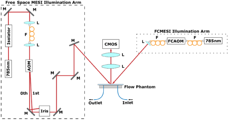
The free space MESI illumination system (Fig. 1) uses a volume-holographic grating (VHG) stabilized laser diode (λ=785 nm, LD785-SEV300, Thorlabs Inc.) [20]. Optical correction of the abnormal beam shape is applied by coupling the light into an optical fiber and then terminating the fiber with a collimating lens to produce a circular beam (Fig. 1). The collimated output is passed through a free space AOM (AOMO 3100-125, Gooch and Housego; rise time of 160 ns) and an iris is then used to select the first diffraction order of the AOM. Using mirrors, the light is directed towards the sample. The imaging optics consists of two lenses (AF Nikkor 50 mm f/1.8D, Nikon, and AF Micro-Nikkor 105 mm f/2.8D, Nikon) and gives the system an approximately 2x magnification. The collected light is imaged onto a monochrome camera (acA1920-155um, Basler). Light throughput of the AOM is controlled by a radiofrequency (RF) driver (97-03307-34, Gooch and Housego). To synchronize image acquisition at the camera with the AOM modulation, a data acquisition device (DAQ) from National Instruments (USB-6363) is used. Figure 1 shows the key components of this optical system. Data acquisition was handled with custom software that interfaced with the camera and DAQ. This software allowed for collecting a set number of frames at different exposure times and saved the resulting images. With our hardware and software setup, a sequence of MESI images was acquired at approximately 2.1 frames per second (fps).
Fig. 1.
Schematics for each of the MESI system designs tested in this work. Left) The traditional free space MESI system requires optical correction of the beam output before passing it through the AOM and selecting the first diffraction order with an iris. Mirrors are then used to steer the beam towards the sample and backscattered light is collected by a 2x magnification lens system and imaged onto a camera. Right) The FCMESI system uses a fiber-coupled laser and FCAOM before terminating the fiber in a collimating lens to illuminate the sample. These components replace the entirety of the illumination optics required in previous MESI systems. The collection optics were the same as before. M: Mirror. L: Lens. F: Fiber.
The working principles of the FCMESI illumination system (Fig. 1) are identical to those of the free space system. The only differences are related to redesigning the illumination arm of the system by choosing fiber-coupled hardware to reduce the instrumentation complexity. For the FCMESI system, the VHG-stabilized laser diode was also fiber-coupled (LD785-SAV50, Thorlabs Inc.) and its output was connected to the FCAOM (T-M150-0.5C2W-3-F2S, Gooch and Housego; rise time 50 ns) input fiber via a mating sleeve. The maximum optical throughput of this configuration was measured to be 60%. The FCAOM fiber output was connected to an adjustable focal length collimating optic that was adjusted to illuminate the desired field of view (FOV). The collection optics were identical to those used in the free space system. A DAQ (USB-6351, National Instruments) and RF driver (1150AF-AINA-2.5HCR, Gooch and Housego) were used as before to modulate light throughput and to trigger the camera, and this system achieved a framerate of 2.1 fps. A schematic of the FCMESI system is also shown in Fig. 1. The exclusive use of fiber-coupled components for the illumination arm provided a substantially simpler and more compact system than before. Furthermore, the use of fiber-based components and mating sleeves removes the need for careful alignment and realignment of optical components, as well as minimizes the number of pieces that can collect dust, which is especially important in clinical settings and in laboratories outside of the field of optics.
The ability of both the AOM and FCAOM to gate the laser illumination was tested using an appropriate photodiode (DET10N, Thorlabs Inc.). A pulse sequence, covering the first ten exposure times in the MESI pulse sequence, was supplied to each of the two AOMs and the optical power was measured. The stability of the amplitude gating across exposure times was also tested by collecting 100 MESI frames at 15 exposure times each and finding the mean pixel intensity over a 100 × 100 region of interest (ROI) in each frame.
2.2. Microfluidic experiment
Microfluidic flow phantoms were used to test the ability of the FCMESI system to quantify changes in flow [21]. The flow phantoms are made of polydimethylsiloxane (PDMS) with the addition of titanium dioxide to mimic the scattering properties of tissue [21,22]. A 300 × 300 µm square channel was embedded within the phantom with a glass coverslip bonded on top, and plastic tubing was connected to produce an inlet and outlet to the channel.
A solution of 1.1 µm diameter polymer microspheres in deionized water was used to produce a solution to mimic the optical properties of blood at 785 nm [23]. Specifically, Mie theory was used to calculate the scattering coefficient of the microspheres and the concentration was then adjusted to mimic the reduced scattering coefficient of blood (1.3 mm-1) [23]. By volume, the solution consisted of 4.8% microsphere solution (5100A, Thermo Fisher Scientific), 0.1% Tween 20 (P1379-100 ML, Sigma-Aldrich) to prevent the clumping of the microspheres, and the remainder was deionized water.
Flow within the system was regulated with a flow control system as in [20]. In summary, the microsphere solution was stored in a reservoir connected to a pressure regulator (MFCS-EZ, Fluigent, Inc.). The outlet of the reservoir was connected to plastic tubing that connected the reservoir to the microfluidic channel inlet; the outlet of the microfluidic channel was placed in a separate collection reservoir. Flow was monitored at two different points using two separate flow sensors (FLU_M, Fluigent, Inc.), one before the channel and one after. Both flow sensors were connected to a control hub (FRP, Fluigent, Inc.) that interfaced with the control computer.
Flow speed was set using Microfluidics Automation Tool software (Fluigent, Inc.), and a protocol was designed to create a step function in flow speeds, ranging from 1-10 mm/s at an interval of 1 mm/s. Each step was held for 90 seconds, and the entire protocol was followed by a 30 second period where flows was set to 0 mm/s. The total experiment time was 15.5 minutes. This protocol was run both while imaging with the free space MESI system and the FCMESI system. MESI images were acquired continuously throughout the protocol for a total of 1950 image sequences, with each sequence consisting of 15 images collected at 15 different exposure times ranging from 50 µs to 80 ms [17]. For both MESI systems, the protocol was run 3 separate times, with the start of each trial separated by approximately 20 minutes.
2.3. Animal preparation
Animal procedures followed protocols approved by the Institutional Animal Care and Use Committee at The University of Texas at Austin. The preparation of mice with cranial windows and the subsequent imaging techniques have been detailed before [24,25]. Mice were anesthetized with isoflurane and body temperature was maintained with a heating pad during all procedures. Craniotomies were performed in two mice (C57, Charles River) to remove a portion of the skull and replace it with a glass coverslip held in place by dental cement [24]. A photothrombotic stroke was induced in one of the mice by retro-orbitally injecting Rose Bengal dye (15 mg/kg) and then focusing 532 nm light on a penetrating arteriole in the motor cortex [7,24]. MESI was performed 11 days after stroke induction, and each mouse was imaged through the cranial window using both the free space and FCMESI systems. For each imaging session, 56 sequences of 15 frames at 15 different exposure times were acquired.
2.4. MESI image analysis
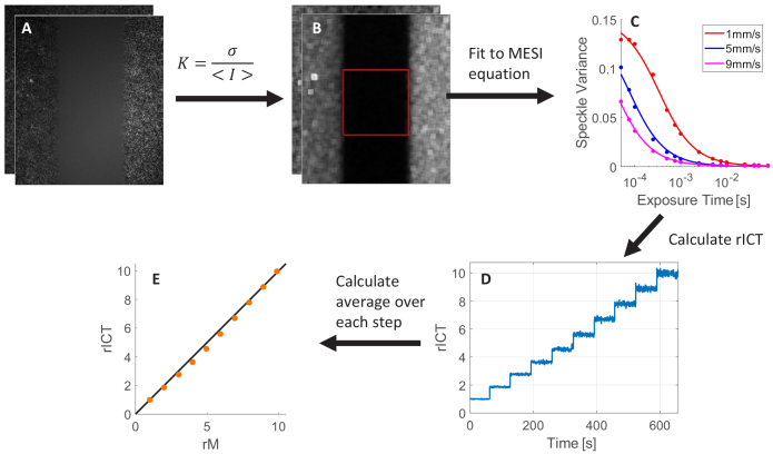
For every raw image collected (Fig. 2.A), the speckle contrast was calculated over a 7 × 7 pixel sliding window to produce the speckle contrast image (Fig. 2.B) according to the definition of speckle contrast (K):
| (1) |
where is the standard deviation and is the average of intensity over a sliding window of pixels [14,16]. For the microfluidics experiments, a 90 × 90 pixel ROI was chosen to correspond to the width of the microfluidic channel in the images. Within this ROI in the speckle contrast images, the arithmetic mean was calculated to produce a single speckle contrast value (Fig. 2.C) at each exposure time. Using this average value, the inverse correlation time (ICT), a measure of flow, was found by fitting the measured speckle variance K2(T) to the MESI equation:
| (2) |
where is a constant instrumentation factor, T is the exposure time, is the correlation time ( is the ratio of collected photons undergoing dynamic scattering events to the total number of collected photons, and is the noise arising from experimental noise and due to simplifying assumptions made in the model [17]. Given issues in the numerical stability of fitting results in Eq. (2), was chosen to be a constant value during the fitting process to remove 1 of 4 variables from the fitting process [17]. The value of was chosen by finding the median value of K for each exposure time for frames in the 1 mm/s step in the microfluidics step function, fitting this data to Eq. (2), and selecting the resulting value as its true constant value.
Fig. 2.
Image Processing steps for microfluidics analysis. A) Raw images were collected as sequences of 15 images at different exposure times. B) A 90 × 90 pixel ROI, denoted by the highlighted red box, was chosen in the speckle images. C) Speckle contrast is averaged over the ROI for each exposure time and the data (dots) is then fit to the MESI equation (curves). D) From the speckle contrast data, rICT was found, producing a timecourse of rICT values. E) Averaging the rICT for each step in the step profile and comparing it to relative microfluidics flow shows the ability of MESI to quantify changes in flow.
To remove the impact of the transition time between flow speeds in the flow protocol, 25 frames of data on each side of the midpoint of the transition between speeds were removed. This cropping of the data and the subsequent fitting to the MESI equation produced a sequence of ICT values corresponding to the 10 steps in the step function. All ICT values were normalized to the mean ICT value for the slowest flow speed to produce a timecourse of relative ICT (rICT) values (Fig. 2.D). The relative microfluidics flow (rM) was found by taking the mean flow value of the two flow sensors and then taking the mean at each flow speed, normalizing to the first step. The rICT was then plotted against relative microfluidics flow for each flow speed (Fig. 2.E).
For each step in the step function, the arithmetic mean of the ICT was found for each trial. Furthermore, using the rICT and the mean of the values at each step allowed us to calculate the mean percent deviation in accuracy (ΔACC) and in repeatability (ΔREP) at each step according to the following equations:
| (3) |
| (4) |
where is the mean rM value at a step and is the mean rICT value.
These metrics allow for quantifying the ability to accurately determine changes in flow (ΔACC) and the stability of those measurements (ΔREP). Three separate trials were performed on each system and the mean and standard deviation of ΔACC and ΔREP were found for each.
For in vivo imaging, the speckle contrast was calculated for each of the images. All images captured at the same exposure were averaged together to produce one dataset consisting of 15 average images for each of the 15 different exposure times used. The ICT was then found over the entire relevant FOV by fitting the data at each pixel to the MESI equation. For the imaging of the stroke model, three ROIs were chosen, corresponding to a vessel, the parenchyma, and the infarct, and the goodness of fit to the MESI equation was determined for each system.
3. Results
3.1. AOM gating
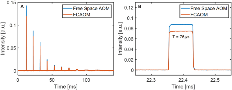
Both the free space AOM and the FCAOM showed similar ability to gate the optical signal for a MESI sequence of different exposure times (Fig. 3.A). For the ten different exposure times, each AOM modulated the optical throughput to decrease instantaneous optical power as the exposure times increased. As the free space AOM and FCAOM had unique calibration curves, the absolute value of the optical power is different between each pulse sequence, but each produces a pulse sequence of comparable shape. Furthermore, each individual pulse within the sequence had similar shape, form, and rise time, despite different absolute measured values (Fig. 3.B). Similarly, the results from acquiring 100 MESI sequences over a 100 × 100 pixel ROI on each system showed that for free space MESI the standard deviation in pixel intensity across all exposure times and all frames was 1.2% and for FCMESI was 0.98%. These results indicate that there is no substantial difference in ability between the two systems to generate MESI pulse sequences.
Fig. 3.
Gating of the MESI pulse sequence. A) For a sequence of 10 separate exposure times, the free space AOM and FCAOM were both able to gate the signal for all 10 exposure times, although unique calibrations lead to different intensity values for each case. B) A zoomed in view of the second pulse with exposure time T of 75 µs shows that both the free space AOM and FCAOM can resolve the pulse with the same pulse shape.
3.2. Microfluidics
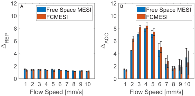
For the 6 runs of the microfluidics flow protocol (3 for each system), rICT is plotted against rM for each of the 10 speeds in the step function (Fig. 4). Although rICT and rM are not equal across all steps, they are similar throughout the entire step function. Significantly, the rICT from the free space MESI system and from the FCMESI trials follow the same general pattern, indicating that the performance of the FCMESI system when measuring changes in flow in a microfluidic channel is comparable to that of more traditional free space MESI. The ΔREP was excellent in all trials, with the upper bound always being less than 2% across all flow speeds (Fig. 5.A). The maximum ΔACC for both systems was less than 10% for both systems, and although the free space MESI system has lower error in accuracy at a few flow speeds, the difference was well within the potential measurement error in flow from the flow sensor (Fig. 5.B). Altogether, this data demonstrates that the FCMESI system had comparable accuracy and repeatability as compared to the free space MESI illumination system, despite the changes in hardware.
Fig. 4.
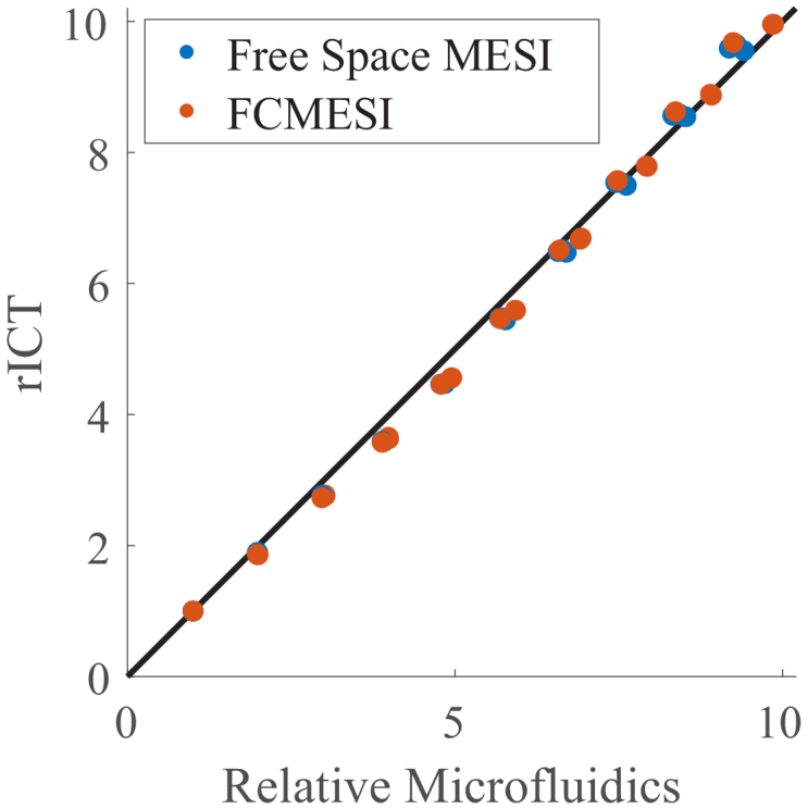
Relative flow at each step for all 6 runs. The mean rICT at each step is shown by each marker, with the FCMESI results indicated by orange and free space MESI by blue. Performance was worst at the middle speeds and consistently underestimated the relative ICT there by a small amount. All trials show significant agreement between each run and the true flow value
Fig. 5.
Percent deviation in accuracy and repeatability measurements, with error bars denoting the standard deviation. The FCMESI performance is denoted by the orange bars while the free space MESI system performance is shown in in blue. A) Percent deviation in Repeatability. For both systems, the error in repeatability is similar and minimal. B) Percent Deviation in Accuracy. The error in accuracy is less than 10% at all flow speeds, although it is worst at the middle speeds, consistent with observations from Fig. 4. Even though free space MESI has substantially lower error in accuracy at speeds of 2-3 mm/s, these differences are still small in amplitude and fall within the range of potential error in the measurements of actual flow speed.
As the flow speed in the microfluidics system has been demonstrated to be remarkably stable, issues in accuracy and repeatability in rICT are caused by errors in MESI imaging and fitting to the MESI equation [20]. In terms of accuracy, MESI seems to systematically underestimate flow in the majority of cases, especially for the speeds of 3-5 mm/s, consistent with previous results [20]. This issue is likely caused by the stability of the numeric calculations, especially the fact that was viewed as a constant, potentially introducing a systematic bias. This could be addressed with a different way of fitting , a different fitting algorithm, or even utilizing a different model or using several models depending upon flow conditions [26]. Despite these potential numerical shortcomings, FCMESI is able to quantify changes in flow with accuracy and repeatability on the level of previous MESI systems, and these systems have been shown to have significant benefits in quantifying changes in flow compared to single-exposure LSCI [17].
3.3. In vivo imaging
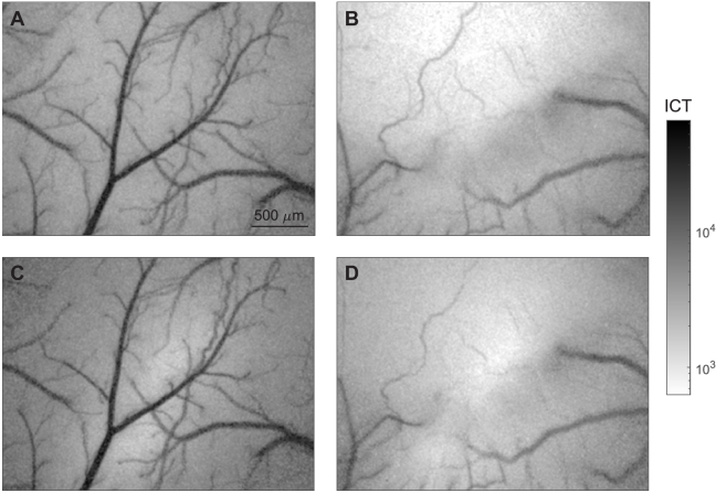
In the mouse imaging, both the FCMESI system and free space MESI system were able to detect the infarct in the case of the stroke mouse and map the vasculature of the healthy mouse (Fig. 6). Qualitatively, all major features on the cortical surface are clearly visible in both sets of images, showing that FCMESI can image neurovascular networks. Interestingly, both show the infarct beginning to recanalize, showcasing the ability of both systems to find longitudinal changes in CBF.
Fig. 6.
In vivo Imaging. A) Image of control mouse collected on the free space MESI system. B) Image of stroke model collected on the free space MESI system with the infarct at the top half. C) Image of control mouse collected on the FCMESI system. D) Image of stroke model collected on the FCMESI system with the infarct in the top half. All images have the same scale.
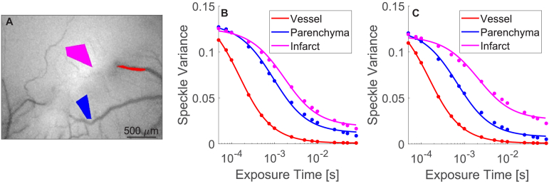
To further demonstrate the ability of FCMESI in widefield mouse imaging, 3 different ROIs were chosen within the stroke model. Each of these 3 ROIs corresponded to a different significant feature: a vessel, the parenchyma, and the infarct (Fig. 7.A). Speckle contrast was averaged across each ROI and fit to Eq. (2) and the fits were plotted against the measured data (Fig. 7.B). These results were compared to the fits for the same ROIs in the free space image (Fig. 7.C). Table 1 compiles the ICT values extracted from these curves, the mean squared error (MSE) between each fit and the data, as well as the relative percent difference between ICT measurements in each system. For both systems, ICT was highest in the vessel and lowest in the infarct, consistent with expectations. MSE increased from vessel to parenchyma to infarct for each system, suggesting a correlation between increased flow and increased goodness of fit to the MESI equation. The ICT values in the vessel showed remarkable agreement between the systems (less than 1% difference), whereas the parenchyma and infarct showed an increased percent relative difference. This is likely in part due to the quality of fits decreasing from vessel to infarct, as increased MSE is consistent with increased disagreement between ICT values. Furthermore, the fact that the disagreement increases with decreasing flow indicates that the model used may be impacting performance [26,27]. Finally, these comparisons also assumed that CBF was constant between using each system, which also introduces another source of error. Despite the disagreement between ICT values, these fits demonstrate that FCMESI can discriminate between the different flow rates in different tissue structures in a mouse brain, especially within the larger vasculature structure.
Fig. 7.
ROI analysis in stroke model. A) Three ROIs were chosen, corresponding to a vessel (red), parenchyma (blue), and the infarct (magenta). B) The average speckle variance in each ROI (colored dots) from the FCMESI image was plotted against the fit from the MESI equation. C) The average speckle variance in each ROI (colored dots) from the free space MESI image was plotted against the fit from the MESI equation. Qualitatively, these curves look similar, although the parenchyma curve is shifted downwards from the FCMESI case to the free space MESI case.
Table 1. ROI Comparison Between Systems.
| System | ICT [1/s] | MSE | Relative Percent Difference in ICT | |
|---|---|---|---|---|
| Vessel | Free Space MESI | 8595 | 0.0158 | 0.675 |
| FCMESI | 8537 | 0.0161 | ||
| Parenchyma | Free Space MESI | 2336 | 0.0262 | 19.8 |
| FCMESI | 1873 | 0.0299 | ||
| Infarct | Free Space MESI | 857 | 0.0359 | 25.2 |
| FCMESI | 1073 | 0.0342 |
4. Conclusion
In this paper, we have demonstrated a redesigned fiber-coupled MESI illumination arm using an FCAOM. We demonstrated that FCMESI can gate optical signals with similar accuracy and time resolution to previous systems. Both systems achieved a frame rate of 2.1fps, sufficient for imaging transient events on the order of the human heartbeat. This framerate could be increased on both systems by reducing the number and duration of the exposure times used [28]. Through microfluidics experiments, we demonstrated the ability of FCMESI to detect and quantify changes in flow, ranging in speed from 1–10 mm/s. Compared to previous free space MESI illumination systems, FCMESI quantified changes in flow with a similar accuracy and repeatability, indicating that the hardware changes in an FCMESI system do not negatively affect performance in detecting changes in flow. In a mouse model, FCMESI was able to image the cortical surface comparably to previous MESI systems. Inside the vasculature, both systems showed a high degree of agreement in ICT measurements, although this significantly decreased in the parenchyma and infarct, suggesting the need for adopting a model that accounts better for low flow conditions outside of larger vasculature [26,27].
This FCMESI illumination system has identical working principles to previously described systems but with more simple and compact hardware. These hardware changes are significant in that they produce a system with simple optical requirements on the level of LSCI while still maintaining the same interpretation of results as in the previous literature. This advantage differentiates FCMESI from synthetic MESI (syMESI), a MESI technique that avoids the need for an AOM by acquiring all images at the same exposure time and then adding them together to synthetically create longer exposure time images [29–31]. In general, syMESI requires a more expensive high speed detector and comes at the expense of spatial resolution; although it has been demonstrated with a widefield camera and spatial resolution comparable to other MESI methods, questions remain about the interpretation of in vivo results due to the constraints required for adequate temporal sampling [29–31]. Although syMESI shows promise, the more limited literature on its use and adoption, especially in vivo, leaves the need for improving current AOM-based MESI systems.
The hardware changes in FCMESI remove a barrier for the adoption of MESI to new applications, both intraoperatively and in novel research settings. Given the benefits of MESI, the adoption of FCMESI in settings where LSCI is currently used will allow for accurate monitoring of CBF in a host of applications, ranging from neurosurgery to neuroscience.
Funding
University of Texas at Austin10.13039/100008562 (Portugal Program); National Institutes of Health10.13039/100000002 (EB011556, NS108484, T32EB007507).
Disclosures
The authors declare that there are no conflicts of interest related to this article.
Data availability
Data underlying the results presented in this paper are not publicly available at this time but may be obtained from the authors upon reasonable request.
References
- 1.Richards L. M., Kazmi S. S., Olin K. E., Waldron J. S., Douglas J., Fox J, Dunn A. K., “Intraoperative multi-exposure speckle imaging of cerebral blood flow:,” J. Cereb. Blood Flow Metab. 37(9), 3097–3109 (2017). 10.1177/0271678X16686987 [DOI] [PMC free article] [PubMed] [Google Scholar]
- 2.Parthasarathy A. B., Weber E. L., Richards L. M., Fox D. J., Dunn A. K., “Laser speckle contrast imaging of cerebral blood flow in humans during neurosurgery: a pilot clinical study,” J. Biomed. Opt. 15(6), 066030 (2010). 10.1117/1.3526368 [DOI] [PMC free article] [PubMed] [Google Scholar]
- 3.Raabe A., Beck J., Gerlach R., Zimmermann M., Seifert V., “Near-infrared indocyanine green video angiography: a new method for intraoperative assessment of vascular flow,” Neurosurgery 52(1), 132–139 (2003). 10.1227/00006123-200301000-00017 [DOI] [PubMed] [Google Scholar]
- 4.Raabe A., Van De Ville D., Leutenegger M., Szelényi A., Hattingen E., Gerlach R., Seifert V., Hauger C., Lopez A., Leitgeb R., Unser M., Martin-Williams E. J., Lasser T., “Laser Doppler imaging for intraoperative human brain mapping,” NeuroImage 44(4), 1284–1289 (2009). 10.1016/j.neuroimage.2008.10.049 [DOI] [PubMed] [Google Scholar]
- 5.Prinz V., Hecht N., Kato N., Vajkoczy P., “FLOW 800 allows visualization of hemodynamic changes after extracranial-to-intracranial bypass surgery but not assessment of quantitative perfusion or flow,” Oper. Neurosurg. 10(2), 231–239 (2014). 10.1227/NEU.0000000000000277 [DOI] [PubMed] [Google Scholar]
- 6.Foster C. H., Morone P. J., Tomlinson S. B., Cohen-Gadol A. A., “Application of indocyanine green during arteriovenous malformation surgery: evidence, techniques, and practical pearls,” Front. Surg. 6, 70 (2019). 10.3389/fsurg.2019.00070 [DOI] [PMC free article] [PubMed] [Google Scholar]
- 7.Williamson M. R., Franzen R. L., Fuertes C. J. A., Dunn A. K., Drew M. R., Jones T. A., “A window of vascular plasticity coupled to behavioral recovery after stroke,” J. Neurosci. 40(40), 7651–7667 (2020). 10.1523/JNEUROSCI.1464-20.2020 [DOI] [PMC free article] [PubMed] [Google Scholar]
- 8.He F., Sullender C. T., Zhu H., Williamson M. R., Li X., Zhao Z., Jones T. A., Xie C., Dunn A. K., Luan L., “Multimodal mapping of neural activity and cerebral blood flow reveals long-lasting neurovascular dissociations after small-scale strokes,” Sci. Adv. 6(21), eaba1933 (2020). 10.1126/sciadv.aba1933 [DOI] [PMC free article] [PubMed] [Google Scholar]
- 9.Sato T., Suzuki K., Sakuma J., Saito K., “Clipping Cerebral Aneurysm,” in Video Atlas of Intraoperative Applications of Near Infrared Fluorescence Imaging , Aleassa E. M., El-Hayek K. M., eds. (Springer International Publishing, 2020), pp. 27–34. [Google Scholar]
- 10.Gruber A., Dorfer C., Standhardt H., Bavinzski G., Knosp E., “Prospective comparison of intraoperative vascular monitoring technologies during cerebral aneurysm surgery,” Neurosurgery 68(3), 657–673 (2011). 10.1227/NEU.0b013e31820777ee [DOI] [PubMed] [Google Scholar]
- 11.Martin N. A., Bentson J., Viñuela F., Hieshima G., Reicher M., Black K., Dion J., Becker D., “Intraoperative digital subtraction angiography and the surgical treatment of intracranial aneurysms and vascular malformations,” J. Neurosurg. 73(4), 526–533 (1990). 10.3171/jns.1990.73.4.0526 [DOI] [PubMed] [Google Scholar]
- 12.Matthew U., Saksham G., Nicholas J., Marissa L., Nguyen V., Joanne D., Aaron L., Stefania P., Ayaz M. K., Linda S. A., Ali A.-S. M., Hasan Z., Timothy R. S., Rania A M., “Computed tomography angiography versus digital subtraction angiography for postclipping aneurysm obliteration detection,” Stroke 50(2), 381–388 (2019). 10.1161/STROKEAHA.118.023614 [DOI] [PubMed] [Google Scholar]
- 13.Dashti R., Laakso A., Niemelä M., Porras M., Hernesniemi J., “Microscope-integrated near-infrared indocyanine green videoangiography during surgery of intracranial aneurysms: the Helsinki experience,” Surg. Neurol. 71(5), 543–550 (2009). 10.1016/j.surneu.2009.01.027 [DOI] [PubMed] [Google Scholar]
- 14.Boas D. A., Dunn A. K., “Laser speckle contrast imaging in biomedical optics,” J. Biomed. Opt. 15(1), 011109 (2010). 10.1117/1.3285504 [DOI] [PMC free article] [PubMed] [Google Scholar]
- 15.Dunn A. K., “Laser speckle contrast imaging of cerebral blood flow,” Ann. Biomed. Eng. 40(2), 367–377 (2012). 10.1007/s10439-011-0469-0 [DOI] [PMC free article] [PubMed] [Google Scholar]
- 16.Fercher A. F., Briers J. D., “Flow visualization by means of single-exposure speckle photography,” Opt. Commun. 37(5), 326–330 (1981). 10.1016/0030-4018(81)90428-4 [DOI] [Google Scholar]
- 17.Parthasarathy A. B., Tom W. J., Gopal A., Zhang X., Dunn A. K., “Robust flow measurement with multi-exposure speckle imaging,” Opt. Express 16(3), 1975–1989 (2008). 10.1364/OE.16.001975 [DOI] [PubMed] [Google Scholar]
- 18.Postnov D. D., Cheng X., Erdener S. E., Boas D. A., “Choosing a laser for laser speckle contrast imaging,” Sci. Rep. 9(1), 2542 (2019). 10.1038/s41598-019-39137-x [DOI] [PMC free article] [PubMed] [Google Scholar]
- 19.Kazmi S. M. S., Parthasarthy A. B., Song N. E., Jones T. A., Dunn A. K., “Chronic imaging of cortical blood flow using multi-exposure speckle imaging:,” J. Cereb. Blood Flow Metab. 33(6), 798–808 (2013). 10.1038/jcbfm.2013.57 [DOI] [PMC free article] [PubMed] [Google Scholar]
- 20.Sullender C. T., Santorelli A., Richards L. M., Mannava P. K., Smith C., Dunn A. K., “Using pressure-driven flow systems to evaluate laser speckle contrast imaging,” 2022.09.16.508276 (2022). [DOI] [PMC free article] [PubMed]
- 21.Richards L. M., “Laser Speckle Contrast Imaging for Intraoperative Monitoring of Cerebral Blood Flow,” The University of Texas at Austin (2015).
- 22.Kazmi S. M. S., Faraji E., Davis M. A., Huang Y.-Y., Zhang X. J., Dunn A. K., “Flux or speed? Examining speckle contrast imaging of vascular flows,” Biomed. Opt. Express 6(7), 2588–2608 (2015). 10.1364/BOE.6.002588 [DOI] [PMC free article] [PubMed] [Google Scholar]
- 23.Bosschaart N., Edelman G. J., Aalders M. C. G., van Leeuwen T. G., Faber D. J., “A literature review and novel theoretical approach on the optical properties of whole blood,” Lasers Med. Sci. 29(2), 453–479 (2014). 10.1007/s10103-013-1446-7 [DOI] [PMC free article] [PubMed] [Google Scholar]
- 24.Sullender C. T., Mark A. E., Clark T. A., Esipova T. V., Vinogradov S. A., Jones T. A., Dunn A. K., “Imaging of cortical oxygen tension and blood flow following targeted photothrombotic stroke,” Neurophoton. 5(03), 1 (2018). 10.1117/1.NPh.5.3.035003 [DOI] [PMC free article] [PubMed] [Google Scholar]
- 25.Hassan A. M., Wu X., Jarrett J. W., Xu S., Yu J., Miller D. R., Perillo E. P., Liu Y.-L., Chiu D. T., Yeh H.-C., Dunn A. K., “Polymer dots enable deep in vivo multiphoton fluorescence imaging of microvasculature,” Biomed. Opt. Express 10(2), 584–599 (2019). 10.1364/BOE.10.000584 [DOI] [PMC free article] [PubMed] [Google Scholar]
- 26.Postnov D. D., Tang J., Erdener S. E., Kılıç K., Boas D. A., “Dynamic light scattering imaging,” Sci. Adv. 6(45), eabc4628 (2020). 10.1126/sciadv.abc4628 [DOI] [PMC free article] [PubMed] [Google Scholar]
- 27.Liu C., Kılıç K., Erdener S. E., Boas D. A., Postnov D. D., “Choosing a model for laser speckle contrast imaging,” Biomed. Opt. Express 12(6), 3571–3583 (2021). 10.1364/BOE.426521 [DOI] [PMC free article] [PubMed] [Google Scholar]
- 28.Kazmi S. M. S., Balial S., Dunn A. K., “Optimization of camera exposure durations for multi-exposure speckle imaging of the microcirculation,” Biomed. Opt. Express 5(7), 2157–2171 (2014). 10.1364/BOE.5.002157 [DOI] [PMC free article] [PubMed] [Google Scholar]
- 29.Dragojević T., Bronzi D., Varma H. M., Valdes C. P., Castellvi C., Villa F., Tosi A., Justicia C., Zappa F., Durduran T., “High-speed multi-exposure laser speckle contrast imaging with a single-photon counting camera,” Biomed. Opt. Express 6(8), 2865–2876 (2015). 10.1364/BOE.6.002865 [DOI] [PMC free article] [PubMed] [Google Scholar]
- 30.Chammas M., Pain F., “Synthetic exposure with a CMOS camera for multiple exposure speckle imaging of blood flow,” Sci. Rep. 12(1), 4708 (2022). 10.1038/s41598-022-08647-6 [DOI] [PMC free article] [PubMed] [Google Scholar]
- 31.Safi A. M., Hernandez-Isidro C., Cini S., Moka S., Harrah M., Passaglia C. L., Parthasarathy A. B., “Quantitative Cerebral Blood Flow Imaging with Synthetic Single-Shot Multi-Exposure Laser Speckle Imaging,” in Biophotonics Congress 2021 (2021), Paper BW3B.4 (Optica Publishing Group, 2021), p. BW3B.4. [Google Scholar]
Associated Data
This section collects any data citations, data availability statements, or supplementary materials included in this article.
Data Availability Statement
Data underlying the results presented in this paper are not publicly available at this time but may be obtained from the authors upon reasonable request.


