Abstract
Neuromonitoring in naturalistic environments is of increasing interest for a variety of research fields including psychology, economics, and productivity. Among functional neuromonitoring modalities, functional near-infrared spectroscopy (fNIRS) is well regarded for its potential for miniaturization, good spatial and temporal resolutions, and resilience to motion artifacts. Historically, the large size and high cost of fNIRS systems have precluded widespread adoption of the technology. In this article, we describe the first open source, fully integrated wireless fNIRS headband system with a single LED-pair source and four detectors. With ease of operation and comfort in mind, the system is encased in a soft, lightweight cloth and silicone enclosure. Accompanying computer and smartphone data collection software have also been provided, and the hardware has been validated using classic fNIRS tasks. This wear-and-go design can easily be scaled to accommodate a larger number of fNIRS channels and opens the door to easily collecting fNIRS data during routine activities in naturalistic conditions.
Keywords: functional near infrared spectroscopy, neuroimaging, hemodynamics, brain imaging
Specifications table.
| Hardware name | Do-it-yourself functional near-infrared spectroscopy (DIY-fNIRS) headband |
| Subject area | • Psychology • Neuroscience • Educational Tools and Open Source Alternatives to Existing Infrastructure |
| Hardware type | • Measuring physical properties and in-lab sensors • Field measurements and sensors • Electrical engineering and computer science |
| Open Source License | Creative Commons Attribution-ShareAlike license |
| Cost of Hardware | $215 |
| Source File Repository | http://doi.org/10.17605/OSF.IO/AG46P |
1. Hardware in Context
Better understanding of how the brain works in naturalistic environments (e.g., at home, work, or while performing an activity that is typically done outside of the laboratory) can have tremendous impact on the fields of psychology, physiology, behavior science, economics and productivity [1–4]. Functional neuroimaging is a general term for technologies that spatially map brain activity over time. Such technologies include functional magnetic resonance imaging (fMRI), positron emission tomography (PET), electroencephalography (EEG), and functional near-infrared spectroscopy (fNIRS). Unfortunately, most of these technologies are not well adapted for use in naturalistic environments [5]. For example, fMRI and PET are bulky, expensive, and require immobilization of subjects; thus, they can only be used in a laboratory or clinical setting to test a limited number of activities. EEG and fNIRS systems are typically smaller and more economical; thus, they can assess a broader range of activities. However, portable EEG technology typically suffers from poor spatial resolution and susceptibility to motion artifacts. Among these neuromonitoring options, fNIRS provides the best compromise: acceptable tolerance to motion artifacts, good spatial (cm) and temporal resolutions (8 to 10 Hz) and portability [6,7].
fNIRS systems consist of light sources and detectors placed on the scalp to quantify relative changes in oxygenated and deoxygenated hemoglobin in different cortical regions. A single channel for fNIRS sensing is typically referred to as an “optode” and consists of a light source and a detector. A light source may be shared by multiple detectors and vice versa to create multiple sensing channels without adding components. The distance between a source and detector controls the depth of imaging, and source-detector distances can be as little as 5 mm to 10 mm (“short channel”) for detecting and correcting shallow physiological signals or motion artifacts not from the brain [1,8–11] or as much as 20 to 60 mm (“long channel”) [10–13] for detecting hemodynamic activity in the brain. Source-detector distances for “long channels” are selected based on the light source and how deep a user wishes to image into brain tissue: low-cost LED sources have a low depth of penetration in tissue and are used with shorter source-detector distances of 20 to 35 mm, and expensive laser-based sources have greater depth of penetration in tissue and can image deeper into the brain with larger source-detector separations [1,13]. Light source wavelengths are typically selected in near-infrared pairs, wherein the first source ranges from 650 nm - 750 nm and the second source is above 820 nm [14]. Recently, three-wavelength fNIRS systems speculating detection of analytes other than hemoglobin such as water [15] or cytochrome C-oxidase [16,17] have also been developed to either improve calculations of changes in hemoglobin concentrations or to utilize an alternate biomarker for cerebral activity. Three wavelengths have also been used for hemoglobin-only systems, where the third wavelength is selected at a point such as 805 nm, close to the isobestic point of hemoglobin [18,19]. However, most commercial and research systems utilize two wavelengths for their studies. Since our system was intended to be as low-cost as possible, we only utilized two LEDs at 740 nm and 850 nm.
A number of studies have demonstrated the potential use of fNIRS in naturalistic environments using either commercial or custom wearable systems capable of wirelessly transmitting hemodynamic neuromonitoring data to an external device [1,2,4,20–23]. Companies such as Artinis [24] market wireless whole-brain wearable fNIRS cap systems, and research groups such as Von Lühmann et al. [25,26] and Zimmerman et al. [27] (“NinjaNIRS”) have even made their wireless fNIRS hardware designs open source. Unfortunately, large component enclosures and exposed cabling interfacing their subcomponents (source or detector probes, data acquisition circuitry, and broadcasting microcontrollers) have frequently rendered such designs susceptible to damage during use in naturalistic conditions [1,4,11,28–31]. Recently, fully integrated and portable head-mounted systems have been designed by companies such as OBELAB and Newman Brain, which fully enclose all system subcomponents (enclosures, cabling, and electronics) inside headgear shaped similarly to virtual reality (VR) devices. Such systems provide multiple advantages: lower dependence on skilled experts for experimental setup, reduced susceptibility to damage, and easy-to-use accompanying software. Unfortunately, no fully integrated open source systems have been made available to the fNIRS research community. Additionally, available fully integrated systems also struggle from sizeable weight (OBELAB NIRSIT-Lite: 190 g [32], OBELAB NIRSIT: 550 g [33], NewmanBrain, 290 g [34]), which makes them uncomfortable to use over a long period of time.
In this manuscript, we describe a scalable prototype of a low-cost, lightweight, and wireless single-channel fNIRS headband platform that is easy to assemble and use for neuroimaging studies in naturalistic conditions. We have designed single-channel fNIRS hardware and accompanying data collection software (for Android phones and Windows/Mac Computers) that can be assembled for approximately $215. In addition to collecting fNIRS signals, the system can reduce artifacts due to motion and other superficial signals [10,11,13]. We demonstrate the use of this technology to yield reliable results during various fNIRS maneuvers including a breath-holding test, which is known to modulate cortical hemodynamics and is commonly used to validate fNIRS systems.
2. Hardware Description
The technical objective of this manuscript is to lay the foundation for a fully integrated fNIRS headband that is 1) easy for researchers to assemble, 2) simple for research subjects to use at home, and 3) affordable for most users. To meet the first objective, ease-of-assembly and future scalability were adopted as guiding principles in the design process. For the second, anticipated requirements for usability in the home environment were considered, such as child-friendliness and tolerance to mechanical wear and tear, by using cushioning and maximizing use of soft and conformal materials.
The complete hardware system consists of multiple subcomponents: electro-optical components for fNIRS sources and detectors, control electronics for data acquisition and wireless broadcasting, and a lightweight conformal enclosure.
Electro-optical components were chosen as functions of the optical properties, form factor, and cost required to achieve fNIRS signals. For the source of our system, an LED pair consisting of light at 740 nm and 850 nm was selected based on the absorption spectra of oxy- and deoxy-hemoglobin on either side of where the spectra intersect (“isobestic point”). The chosen near-infrared wavelength LEDs has an output radiant intensity not more than 3 mW, which is below the IEC (International Electrotechnical Commission) 60825–1 suggested limit, assuming an area of > 2 mm2. Both LEDs also have relatively narrow spectral bandwidths with peak emission wavelengths at 740 nm and 850 nm with aberrations of approximately +/− 30 nm at 20% of their peak intensities. For the detector, a silicon photodiode was selected with a spectral sensitivity bandwidth encompassing the wavelengths of interest. The dark current of the photodiode is specified to be 2 nA at room temperature. A voltage follower circuit and current-to-voltage conversion circuit are used to activate the LEDs and read the signal detected from the photodiodes, respectively. Both circuits can alternatively be built using low-power, low-noise transimpedance op-amps such as those by Texas Instruments (OPA2380 or OP2377).
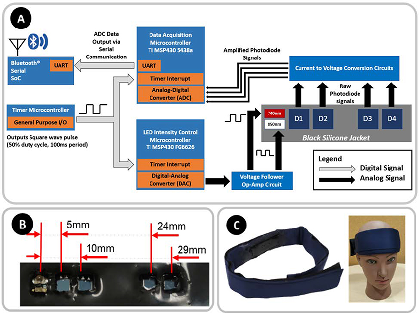
The control electronics for this system were designed for modularity and ease of scalability by any member of the fNIRS community. Unfortunately, not all members of this community have the expertise in hardware engineering necessary to adapt fNIRS technology to their unique experimental requirements. Hence, a divide-and-conquer approach to the design was adopted: three ultra-low-power microcontrollers by Texas Instruments® were selected to manage data-acquisition, LED intensity, and system timing, respectively. The analog-to-digital converter (ADC) of the data-acquisition microcontroller is a 12-bit linear successive-approximation-register (SAR) ADC typically used for data acquisition. The aggregated data are wirelessly transmitted through a peripheral Bluetooth® Serial system-on-a-chip device by Microchip®. Dividing responsibilities across multiple controllers allows the system to be easily scaled up for future endeavors since the firmware development process becomes simpler for any non-engineering professional (or early-career engineers) to learn and customize without needing to learn complex firmware technologies for multitasking on embedded systems. Unsharing of the computational load also enables advanced audiences to add other sensors (e.g., accelerometers) and manage the distribution of system weight over different parts of the head to maximize comfort. The interconnectivity of the subcomponents of the circuit is represented in Figure 1A.
Figure 1:
A) Block diagram illustrating the interconnectivity of the various subcomponents constituting the fNIRS sensing control circuitry. B) Photograph (not to scale) of a prototype optode. C) Photograph showing a model wearing our fNIRS headband device.
For demonstration purposes, the assembled system presented in this manuscript consists of a single near-infrared LED pair (740 nm and 850 nm) and four silicon photodiode detectors placed collinearly at distances of 5 mm, 10 mm, 23 mm, and 28 mm (Figure 1B). This layout of source and detectors was selected to facilitate future decision-making regarding short- and long-channel placement in a prospective multichannel fNIRS system. This system can be scaled up to include 10 detectors and three sets of LED sources, wherein a “set” would constitute a group of multiple sources which can be illuminated together.
The control electronics and electro-optical components are jacketed in a soft, conformal headband enclosure consisting of silicone and cloth components. The electro-optical components are jacketed inside molded silicone that is “glued-on” to a laser-cut cloth. The remaining control electronics and battery are connected to the electro-optical components with flat and flexible cables (FFC) and are enclosed inside a pocket created by attaching folds of the cloth enclosure using Velcro®.
Once fully assembled (Figure 1C), our open source fNIRS headband broadcasts data at 10 Hz, weighs only 142 grams and has a battery life of up to 5 hours (peak current consumption of 84 mA, tested using a 400-mAh lithium-ion polymer, LiPo, battery). The system unit cost is approximately $215 in single-unit volume and is expected to be significantly lower when it is mass-produced. This device has the following advantages for research:
The device will allow home-based use
The device will allow large-scale studies
The device will allow long-duration studies (hours)
The device will allow longitudinal studies
The device will allow treatment response feedback and optimization
The device will allow discovery of new fNIRS applications and knowledge
3. Design files
| Design file name | File type | License Type | File Location |
|---|---|---|---|
| circuitDesigns | ExpressPCB circuit file | CC – sa* | OSF |
| circuitSchematics | Image file for circuitSchematics | CC – sa* | OSF |
| timerMCU | IAR embedded workbench project | CC – sa* | OSF |
| sourceIntensityControlMCU | IAR embedded workbench project | CC – sa* | OSF |
| dataAcquisitionMCU | IAR embedded workbench project | CC – sa* | OSF |
| sw_collectDataMATLAB | MATLAB® AppDesigner project | CC – sa* | OSF |
| sw_collectDataCpp | Visual Studio (C++) project | CC – sa* | OSF |
| sw_collectDataAndroid | Visual Studio (Xamarin.Android C#) project | CC – sa* | OSF |
| 3D_CAD_SiliconeMold | Autodesk Inventor file | CC – sa* | OSF |
| 2D_CAD_ClothEnclosure | LibreCAD file | CC – sa* | OSF |
Creative Commons Attribution-ShareAlike license
circuitDesigns:
ExpressPCB PCB schematic (.sch) and design files (.pcb) with multiple circuits to be cut out along dotted lines on the silk screen.
timerMCU:
IAR Embedded Workbench Firmware project for programming a MSP430F2001 microcontroller to output timing signals to trigger interrupt events in other microcontrollers.
ledIntensityMCU:
IAR Embedded Workbench Firmware project for programming a MSP430FG6626 microcontroller to control LED activation sequences. Additional functionality for controlling LED intensity and reading its digital-to-analog converters is also provided.
dataAcquisitionMCU:
IAR Embedded Workbench Firmware project for programming the main MSP430F5438A microcontroller, which communicates with both the MSP430FG6626 microcontroller and Bluetooth System-on-a-Chip to wirelessly broadcast data. It is responsible for analog-to-digital conversion of the photodiode signal in synchrony with LED pulsing as guided by timer signals.
sw_collectDataCpp:
A bare-bones 2017 Visual C++ program developed to receive and parse through raw wireless Bluetooth® for fNIRS data broadcasted from the fNIRS device.
sw_collectDataAndroid:
An Android application and code for plotting and storing real-time data from the fNIRS device. Additionally, the GUI can be used to annotate when a stimulus is provided to the data.
sw_collectDataMATLAB:
A MATLAB® GUI application for collecting and storing real-time data from the fNIRS device. Additionally, the GUI can be used to annotate when a stimulus is provided to the data.
3D_CAD_SiliconeMold:
An Autodesk Inventor file for making the mold used for enclosing the optodes in soft silicone.
2D_CAD_ClothEnclosure:
A LibreCAD file used as the input for the laser cutter to cut the cloth headband that holds the circuits and silicone-jacketed electronics in place.
4. Bill of Materials
List of Electronic Subcomponents
| Designator on PCB | Description | Manufacturer | Part Number | Qty | Unit Cost | Total Cost |
|---|---|---|---|---|---|---|
| C1, C2 | 100 pF capacitor | KEMET | C0603C101J3GACTU | 2 | $ 0.15 | $ 0.30 |
| C3, C4, C5, C6 | 18 pF capacitor | Vishay Vitramon | VJ0603A180JXACW1BC | 6 | $ 0.12 | $ 0.72 |
| C7, C8 | 12 pF capacitor | Yageo | CC0603JRNPO0BN120 | 2 | $ 0.10 | $ 0.20 |
| C9, C13, C17 | 1 uF capacitor | Vishay Vitramon | VJ0603Y104KXAAC | 3 | $ 0.34 | $ 1.02 |
| C10, C11, C15, C16 | 18 pF capacitor | Vishay Vitramon | VJ0603A180JXACW1BC | 2 | $ 0.12 | $ 0.24 |
| C12 | 0.1 uF capacitor | Vishay Vitramon | VJ0603Y104KXAAC | 1 | $ 0.34 | $ 0.34 |
| C14 | 1 nF capacitor | KEMET | C0603C102K4RECAUTO | 1 | $ 0.19 | $ 0.19 |
| D1, D2, D3, D4 | Photodiode | Vishay | VBPW34S | 5 | $ 1.19 | $ 5.95 |
| D5 | 850 nm LED source | Wurth | 15412085A3060 | 1 | $ 0.53 | $ 0.53 |
| D6 | 740 nm LED source | Marktech | MTSM0074-843-IR | 1 | $ 3.45 | $ 3.45 |
| J1 | 2.54 mm pitch male headers for assembling programming pins | Samtec Inc. | TSW-150-07-T-S | 9 | $ 2.18 | $ 19.62 |
| J2 | 10-pin FFC cable connector | Molex | 522071033 | 2 | $ 1.16 | $ 2.32 |
| R1 | 1 MOhm resistor | Yageo | RC0603FR-071ML | 1 | $ 0.10 | $ 0.10 |
| R2 | 5.1 MOhm resistor | Yageo | RC0603JR-075M1L | 1 | $ 0.10 | $ 0.10 |
| R3 | 20 MOhm resistor | Vishay Dale | CRCW060320M0JPEAHR | 1 | $ 0.48 | $ 0.48 |
| R4 | 50 MOhm resistor | Stackpole Electronics | HMC0603JT50M0 | 1 | $ 0.42 | $ 0.42 |
| R5, R6, R10 | 47 kOhm resistor | Panasonic Electronic Components | ERJ-3GEYJ473V | 4 | $ 0.10 | $ 0.40 |
| R7, R9 | 200 Ohm resistor | Panasonic Electronic Components | ERJ-1GN0R00C | 2 | $ 0.10 | $ 0.20 |
| R8, R18 | 0 Ohm resistor | Stackpole Electronics Inc. | RMCF0603ZT0R00 | 2 | $ 0.10 | $ 0.20 |
| U1, U4 | Op-Amp for LED controller microcontroller | Texas Instruments | OPA2380 | 2 | $ 2.41 | $ 4.82 |
| U2 | Clock timer microcontroller | Texas Instruments | MSP430F2001 | 1 | $ 1.38 | $ 1.38 |
| U3 | LED intensity control microcontroller | Texas instruments | MSP430FG6626 | 1 | $ 10.89 | $ 10.89 |
| U5 | LDO voltage regulator | Texas Instruments | TPS73630DBVT | 1 | $ 2.30 | $ 2.30 |
| U6 | Op-Amp for photodiode signal amplification | Texas Instruments | OPA2377 | 1 | $ 1.60 | $ 1.60 |
| U7 | Data acquisition microcontroller | Texas Instruments | MSP430F5438AIPZR | 1 | $ 7.01 | $ 7.01 |
| U8 | Bluetooth 2.1 classic module | Microchip Technology | RN42N-I/RM | 1 | $ 15.73 | $ 15.73 |
| X2, X3 | 18 MHz crystal | Citizen Finedevice Co Ltd | HC-49/U-S18000000ABJB | 2 | $ 0.66 | $ 1.32 |
| W1 | 6 pos 10” FFC cable with 1.00 mm pitch | Assmann WSW Components | AFFC-100-06-254-11 | 2 | $2.27 | $ 4.54 |
| W2 | 10 pos 4” FFC cable with 1.00 mm pitch | Molex | 152670251 | 1 | $1.86 | $ 1.86 |
| B1 | Lithium-Polymer battery | Adafruit Industries | 1578 | 1 | $7.95 | $ 7.95 |
| B2 | LiPo charger | SparkFun Electronics | PRT-10217 | 1 | $8.95 | $ 8.95 |
| PCB | Single PCB to be cut and separated into pieces | ExpressPCB | Miniboard Pro | 1 | $100.00 | $ 100.00 |
| Total Electronics Related Costs | $204.83 | |||||
Multi-Use Consumable Supplies:
| Item | Description | Manufacturer | Part Number | Qty | Unit Cost | Cost |
|---|---|---|---|---|---|---|
| Dragon Skin FX-Pro (910 g) | 2-Part silicone solution | Smooth-On, Inc. | SODragonskinfxprokit | 28 g | $42.60 | $1.71 |
| Black Silicone Pigment (118 ml) | Black pigment for silicone | Smooth-On, Inc. | SilcPigBLACK4oz | 7 ml | $34.95 | $2.10 |
| Ultimaker 3D Printing Material (750 g) | Black 2.85 mm PLA material | Ultimaker | 1613 | 40 g | $49.95 | $3.00 |
| Polytechno Two Way Stretch Fabric (36” x 60”) | 1 square meter of 97% Polyester, 3% Spandex cloth to be laser-cut into headband enclosure | Shason Textile | WS-B436-424 | 0. 5 | $4.97 | $2.485 |
| Total Multi-Use Consumables Cost | $9.30 | |||||
Cost values rounded up to two significant values
Other Equipment Utilized:
| Item | Description | Manufacturer | Part Number | Cost |
|---|---|---|---|---|
| Ultimaker 3 3D printer | Desktop 3D printer | Ultimaker | B07YN8LTJ4 | $3,850.00 |
| PCB Cutter | Black pigment | Circuit Specialists | PCB CUTTER | $389.00 |
| PLS6.75 Laser Cutter | Laser cutter | Universal Laser Systems | PLS6.75 | $19,400.00 |
| Total Equipment Cost (Multi-Use) | $23,639 | |||
5. Build Instructions
The proposed wearable is an electro-mechanical assembly consisting of three subcomponents: control and sensing electronics, a silicone polymer skin, and a cloth and Velcro® casing. Once assembled, the wearable can be strapped the head of a user to broadcast fNIRS data to the Android Phone application or MATLAB® computer application provided. The assembly of the individual subcomponents and their integration are discussed below.
a. Control and sensing electronics
The control and sensing electronics consist of four small circuits for 1) power management, 2) LED control, 3) data acquisition, and 4) fNIRS sensing that require assembly by soldering relevant components and programming the microcontrollers. The data acquisition board also contains a Bluetooth® data module for broadcasting the fNIRS data. The fNIRS sensing circuits are two small circuits that are connected to each other using two small snippets of wire and to other circuits using cables. All circuits have been designed using ExpressPCB to fit onto a single, 4-layer printed circuit board (PCB) as a cost-savings mechanism; the board can be cut into individual circuits along the outline markers in the provided PCB file in the OSF repository. The fourth circuit (by Sparkfun®) is a detachable power management circuit that provides connection and charging to a LiPo battery.
The circuit components have been selected with both miniaturization and ease-of-assembly in mind. The components (integrated circuits, resistors, capacitors, cable connectors, etc.) need to be soldered onto their respective locations, which can be identified using the provided bill of materials (BOM) and the silk-screen layer of the provided PCB file. Additionally, it is also recommended that the PCBs be cut prior to soldering components onto them.
To functionalize the various microcontrollers in the circuit, they need to be programmed. In this project, programming entails either downloading a file to a microcontroller using a programmer device (U2, U3, U8) or wirelessly configuring a microcontroller using external Bluetooth® devices such as phones and computers (U8). With the exception of components U1 and U8, which must be programmed prior to soldering, all components can be programmed or re-programmed after being mounted onto the board. Hence, it is recommended that U1 and U8 be soldered onto the PCBs at the very end.
U2 is a Texas Instruments (T.I.) MSP430F2001 microcontroller used to manage the timing and synchronization of the system. It can be programmed using a T.I. MSP-TS430PW28A target board and a T.I. Flash Emulation Tool (F.E.T.) programmer. Using the IAR Embedded Workbench software, the “timerMCU” project code can be downloaded to the MSP430F2001 microcontroller. U8 is a Microchip Technology RN42-I/RM system-on-a-chip (SoC) that is used to broadcast Bluetooth® data. The SoC must be wirelessly programmed to a baud rate of 19,200 by following instructions in the “RN41/42 Evaluation Kit User’s Guide” published by Microchip®. Once these devices are programmed, they can be soldered onto their PCBs.
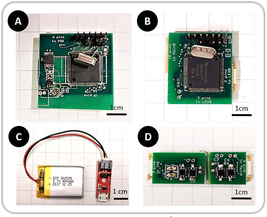
Once the system soldering is complete (Figure 2), the remaining microcontrollers U3 and U7 can be programmed. Prior to programming, the system must be powered using the detachable battery circuit or other voltage source. Using IAR Embedded Workbench, the data acquisition board and LED control board need to be programmed using the “dataAcquisitionMCU” and “sourceIntensityControlMCU” project codes, respectively.
Figure 2:
Images of assembled control circuits: A) Data acquisition and Bluetooth® broadcasting board, B) LED Intensity control board, C) Detachable Sparkfun® LiPo Charger with 400mAh LiPo battery, D) fNIRS sensing electronics
b. Silicone polymer skin
A silicone polymer skin is used to encase the fNIRS sensing electronics into a soft, comfortable, and protective casing that interfaces with forehead skin. The polymer is mixture of a commercially available translucent silicone rubber (Dragon Skin™, BOM: S1) and black-colored color pigment (Silc Pig Silicone Pigment, BOM: S2). This dark liquid polymer mixture, which blocks out ambient light, becomes a flexible solid in the shape of any mold it is provided. The mold was iteratively designed to house the fNIRS sensing electronics in a manner wherein the final LED and photodiode positions are roughly 1 mm away from the head. The polymer mold ensures the fNIRS sensing electronics conform snuggly to the forehead and minimizes movement between the optode and the skin.
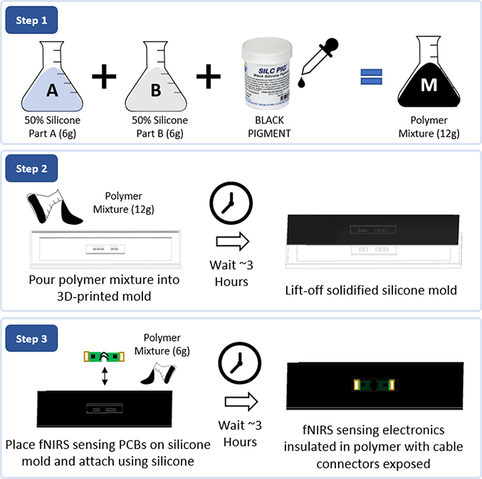
The polymer skin preparation process begins by 3D printing the provided mold design. The polymer skin material is prepared (Figure 3) by mixing an equal amount of the two-part Dragon Skin™ solution (10 g each) by weight (BOM: S1) and 6 drops of a black pigment (BOM: S2). After stirring, the viscous liquid mixture is poured into a 3D-printed mold until the mold is full and is then allowed to cure in air for three hours. To accelerate the curing process, temperature can be elevated, although the mixture will also cure at room temperature. After the mixture is cured, the cured polymer forms a template to fit the fNIRS sensing PCBs with the holes aligned with LEDs and photodiodes on the PCBs. Once the PCBs are correctly aligned and placed in the template, another batch of the silicone-pigment solution (3 g per part, 1 drop) should be poured over the PCBs and left to cure. Note, while pouring the second batch of silicone, the liquid must not rise above the cable connectors at the edges of the fNIRS sensing PCBs. After curing, the assembly needs to be visually inspected to ensure neither the LED nor the photodiode windows were accidentally covered with the polymer. The final system can be wiped clean using rubbing alcohol (70% Ethyl Alcohol).
Figure 3:
Silicone polymer skin assembly for insulating and protecting the fNIRS sensing electronics: Step 1) Prepare polymer mixture by mixing equal parts of silicone parts A and B with 6 drops of black pigment. Step 2) Pour silicone and set polymer mold for three hours, then lift-off. Step 3) Place fNIRS sensing electronics on lifted-off silicone mold and set in place using a fresh batch of polymer mixture.
c. Cloth and Velcro® casing
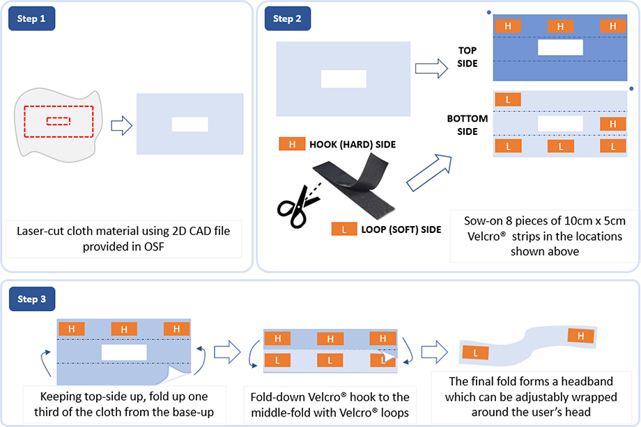
The final subcomponent is a laser-cut cloth enclosure with a rectangular cut at the center for attaching it to the silicone jacketed fNIRS sensing electronics. Assembly is described in Figure 4. The cloth cutout will have an overall size of 68 cm x 23 cm, with a rectangular cut-out at the center sized at 7 cm x 5 cm. Although this cut can be achieved without using a laser cutter, a laser cutting file “clothLaserCut” has been provided in the OSF repository. After laser cutting, small 10-cm pieces of 5-cm wide Velcro® need to be sown onto the select locations as shown in Figure 4. The resulting assembly constitutes a Velcro®-patched cloth that can be attached together into a tube-like formation and wrapped around the head like an adjustable headband.
Figure 4:
Cloth enclosure assembly. Step 1) Laser-cut cloth material using the provided “clothLaserCut” file in the OSF repository. Step 2) Sew on Velcro® hook and loop sides to designated areas to form an enclosable headband. Step 3) Fold cloth enclosure to form a “tube” (held together with Velcro®) to be wrapped around the head of a user.
d. System consolidation
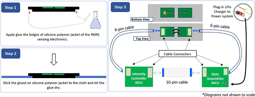
As described in Figure 5, the final step for completing the system is to “glue” the polymer-jacketed fNIRS sensing array onto the cloth and Velcro® casing using the same two-part translucent silicone polymer utilized earlier (1 g per part). Using a small spatula, glue is applied to the tapered edges of the polymer-jacketed fNIRS array and pressed down into the cloth. Once the glue has dried, the remainder of the electronics can be assembled. Interfacing the data acquisition and LED-control PCBs with the polymer-jacketed fNIRS sensing array requires two types of FPC cables: one ten-pin cable between the data acquisition and LED boards and two six-pin cables connecting both the data acquisition and LED boards to the sensing electronics board. The data-acquisition board will be connected to the photodiode end of the fNIRS sensing board, and the LED controller board will be connected to the LED source end of the fNIRS sensing board. At the conclusion of the assembly and programming, the LiPo charger circuit can be plugged in to power the board. After the circuit is powered, the two LEDs in the fNIRS electronics will alternatingly pulse, and the data acquisition board will broadcast Bluetooth® data.
Figure 5:
Consolidation of the remaining components of the fNIRS headband system: Step 1) Apply a small amount of silicone polymer (2 g each of Part A and B) along the tapered edges of the silicone polymer encasing the fNIRS electronics and let dry for three hours. Step 2) Connect flat 6-pin and 10-pin cables as demonstrated in the diagram above to complete assembly of the system. The system can be powered by plugging in the LiPo Charger using the provided female headers.
6. Operation Instructions
The fNIRS headband is very simple to use:
Install either interfacing software (the Android App on the phone or MATLAB®/C++ applications on computer) shared in the repositories above. This “installation” process requires prior installation of Android Studio, MATLAB®, or Visual Studio based on the chosen data collection tool.
Turn on the fNIRS headband by connecting the detachable battery.
Place the fNIRS headband on the forehead of the user and wrap it around the head.
Pair the fNIRS headband and your device wirelessly using your phone or computer operating system: open your Android phone or Bluetooth®-interfacing computer and select the name of the Bluetooth® module associated with the fNIRS headband on the Android-compatible device.
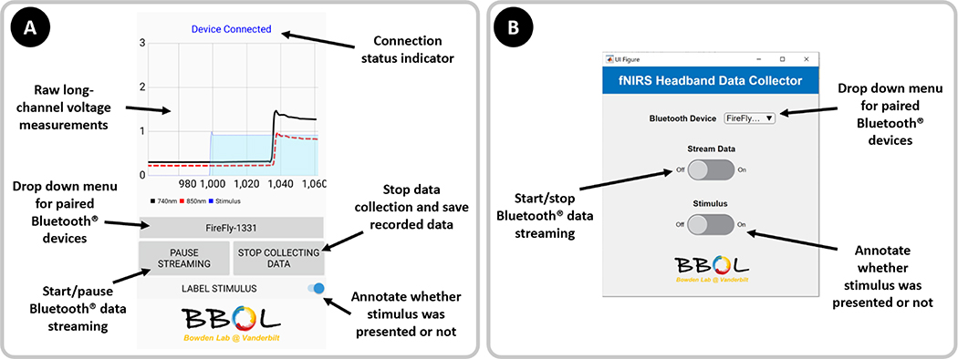
In the interfacing software, select the desired Bluetooth® device from the “drop down menu for paired Bluetooth® devices” of the respective graphical user interface (GUI) in Figure 6.
Press or toggle the “Start/Pause Bluetooth Data Streaming” (Android) or “Start/Stop Bluetooth Data Streaming” (MATLAB®) buttons to start collecting data, and perform experimental activities as desired with the fNIRS headband on (data will be automatically saved locally on the chosen computer or phone). Periods involving a stimulus such as presentation of audio-visual cues or performing neurologically engaging activities can be annotated by toggling the “Label Stimulus” (Android) or “Stimulus” (MATLAB®) buttons shown above.
At the conclusion of the experiment, press the button to “Stop data collection and save recorded data” (Android) or simply toggle the button to “Start/Stop Bluetooth® Data Streaming” (MATLAB®). On the Android phone, data will be saved in the “DCIM/NIRS” directory. For the MATLAB® application, data will be saved in the “data” subdirectory of the current project.
Figure 6:
A) Screenshot of the Android phone application developed using Xamarin.Android. The application allows users to collect raw voltage readings from the fNIRS headband system on the phone for access later. During data collection, users can check the device connection status and annotate data when “stimuli” are applied. B) Screenshot of the MATLAB® computer application to easily connect to and save data from the fNIRS headband system.
7. Validation and Characterization
To validate our fNIRS headband device, we acquired hemodynamic measurements during a breath-holding test, an arithmetic test, and resting states with IRB approval.
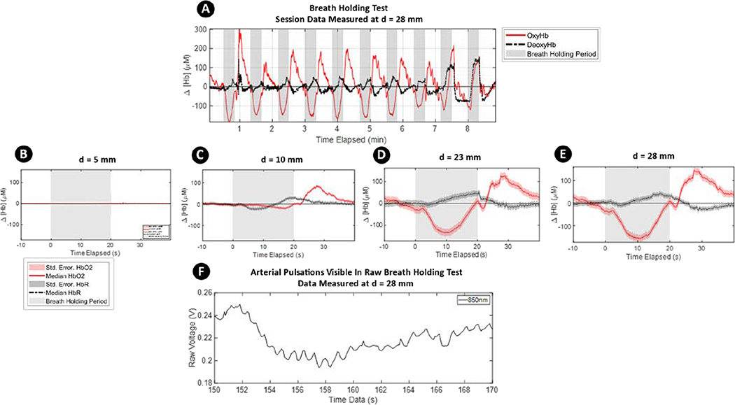
Breath-holding results in a uniform blood oxygenation level dependent (BOLD) response throughout the gray matter of the brain that does not originate from cognitive activity [35,36]. During the experiment, a healthy adult subject was requested to alternate between breathing normally for 30s and holding their breath for 20s. Before each breath-holding period, the subject was instructed to take a deep breath. The breathing and breath-holding cycle were repeated 10 times. The results of the experiment are shown in Figure 7. Figure 7A shows the complete session data from the experiment. The red curve represents the oxyhemoglobin concentration while the dashed black curve represents the deoxyhemoglobin concentration. These raw voltage data were band-pass filtered (0.05Hz to 2Hz) to remove various physiological noises (cardiac, respiratory, Mayer waves) and signal drift. The photodiode readings were then converted to hemoglobin concentrations using the Modified Beer- Lambert Law [37] (). The clear areas in the plot represent normal breathing periods, while the gray background areas represent data collected during breath-holding periods. Block medians (with standard error of the median) of the fNIRS data for the different source-detector separations are shown in Figures 7B to 7E. For each figure, 10 seconds of baseline data before breath holding have been subtracted. It can be observed that as source-detector separation increases, characteristic drops in OxyHb measurements during breath holding periods become more visible, and this trend is reproducible across multiple breath holding cycles. The drop in OxyHb at the onset of breath holding followed by a sharp recovery is consistent with both fNIRS [38–40] and fMRI [41,42] studies and demonstrates that the grey matter of the brain was successfully imaged.
Figure 7:
Physiological validation using a breath-holding test. A) Complete session data. The solid red lines represent OxyHb, dashed black lines are DeoxyHb, and shaded gray areas represents breath-holding periods. Characteristic dips and recovery in OxyHb are visible in these data. B thru E) Block median with highlighted standard error of the median of 10 cycles measuring the change in baseline measurement with respect to the 10 seconds preceding the breath-holding period. An increase in source-detector separation results in deeper imaging into the head F) A segment of raw, unprocessed data from our fNIRS device during 850-nm LED light input is shown. Arterial pulsations are visible in the figure
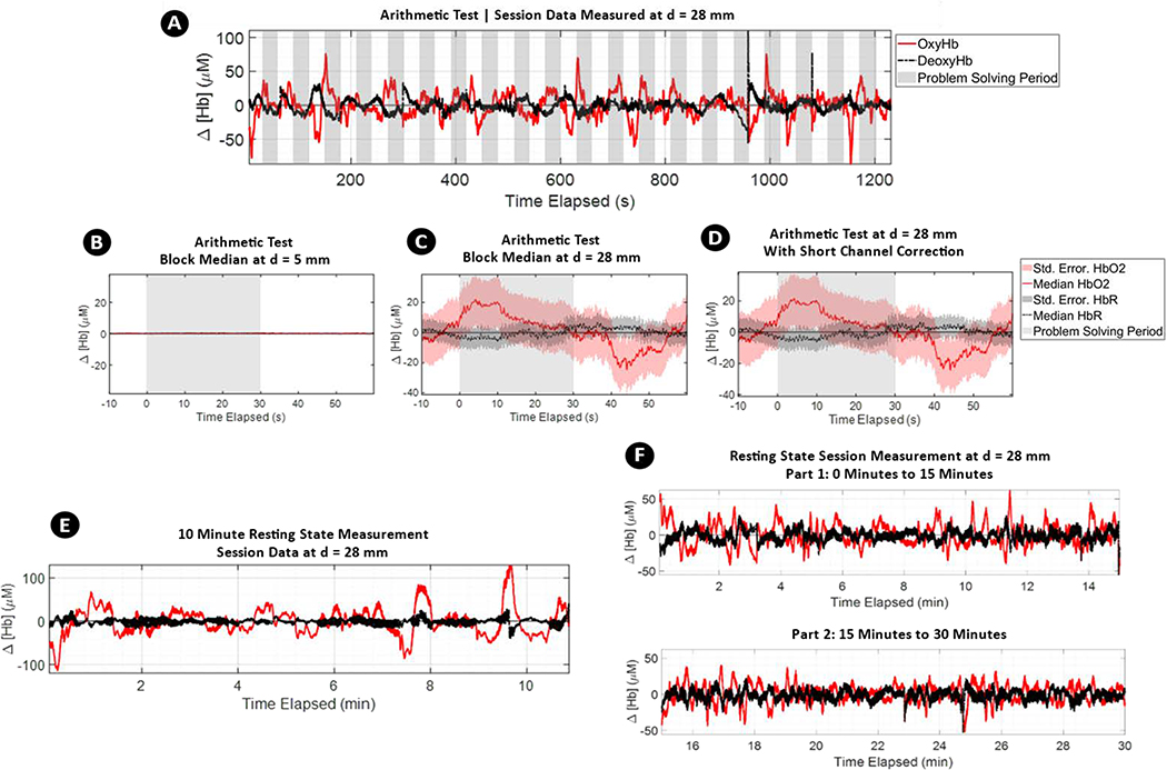
Data from shorter channels, such as those featured in Figures 7C and 7D, are typically used by researchers for sensing non-cortical hemodynamic activity and can be subtracted from long-channel data to restrict imaging to cortical activity [10,43,44]. An example of short channel correction can be seen in Figure 8, which presents results from an arithmetic test. The arithmetic test was conducted for 20 minutes and consisted of 20 cycles of 30s of relaxation and 30s of problem solving. The device was positioned at the F2 location on the forehead of a subject. In Figure 8A, uncorrected arithmetic test data for the complete 20-minute session are presented. For this duration, a recurrent rise in OxyHb can be observed at the beginning of each problem-solving phase. In Figures 8B and 8C, processed data for the short channel at d = 5mm and long channel at d = 28mm are shown. Simply subtracting Figure 8B from 8C gives us 8D: a “short-channel corrected” fNIRS measurement without non-cortical data. While various other methods exist for such short-channel correction [45,46], all such methods serve to remove signal features such as motion or respiratory artefacts unrelated to cognitive activity. The recurrent rise in OxyHb during the problem-solving phase of the arithmetic test correctly reproduces other cognitive load experiments evaluating cognitive load and presents a visible hemodynamic response [47,48]. To demonstrate the stability of the fNIRS measurement, 10-minute and 30-minute resting-state fNIRS measurements of a subject seated on a chair are also shown in Figures 8E and 8F, respectively.
Figure 8:
A) Complete session data of Arithmetic Test. The solid red lines represent OxyHb, dashed black lines DeoxyHb, and shaded gray area represent problem solving periods. Characteristic rises of OxyHb during problem solving phases are visible. B thru D) Block median with highlighted standard error median of 20 cycles measuring change in baseline measurement with respect to the 10 seconds preceding arithmetic problem-solving period. In B and C, change in hemoglobin concentrations are shown from the shortest detector at d = 5 mm and the farthest detector d = 28 mm. In D, the short channel signal from d = 5 mm is subtracted from long channel signal at d = 28 mm to demonstrate short channel correction. E) Resting state fNIRS measurements for 10 minutes. F) Resting state fNIRS measurements for 30 minutes. Both data demonstrate stability of the measurements throughout the imaging durations.
8. Acknowledgement
This work was funded by the Dorothy J. Wingfield Phillips Chancellor Faculty Fellowship and National Institutes of Health (NIH) grant # 1 R21 MH123873–01.
Footnotes
9. Declaration of interest
Declarations of interest: none
10. Human and animal rights
We have carried out our work in accordance with The Code of Ethics of the World Medical Association (Declaration of Helsinki) and Uniform Requirements for manuscripts submitted to Biomedical journals. This work was conducted under approval of IRB#192103 at Vanderbilt University.
References
- [1].Pinti P, Aichelburg C, Gilbert S, Hamilton A, Hirsch J, Burgess P, Tachtsidis I, A Review on the Use of Wearable Functional Near-Infrared Spectroscopy in Naturalistic Environments, Jpn. Psychol. Res. 60 (2018) 347–373. 10.1111/jpr.12206. [DOI] [PMC free article] [PubMed] [Google Scholar]
- [2].Hamilton A, Pinti P, Paoletti D, Ward JA, Seeing into the Brain of an Actor with Mocap and fNIRS, in: ISWC’18 Proc. 2018 ACM Int. Symp. Wearable Comput., 2018: pp. 216–217. 10.1145/3267242.3267284. [DOI] [Google Scholar]
- [3].(舟根司) Funane T, (敦森洋和) Atsumori H, (鈴木敦) Suzuki A, (木口雅史) Kiguchi M, Noncontact brain activity measurement system based on near-infrared spectroscopy, Appl. Phys. Lett. 96 (2010) 123701. 10.1063/1.3367737. [DOI] [Google Scholar]
- [4].McKendrick R, Mehta R, Ayaz H, Scheldrup M, Parasuraman R, Prefrontal Hemodynamics of Physical Activity and Environmental Complexity During Cognitive Work, Hum. Factors. 59 (2017) 147–162. 10.1177/0018720816675053. [DOI] [PubMed] [Google Scholar]
- [5].Izzetoglu K, Bunce S, Izzetoglu M, Onaral B, Pourrezaei K, Functional near-infrared neuroimaging, in: Proc. 26th Annu. Int. Conf. IEEE Eng. Med. Biol. Soc. Vols 1–7, 2004: pp. 5333–5336. [DOI] [PubMed] [Google Scholar]
- [6].Zhang Q, Yan X, Strangman GE, Development of motion resistant instrumentation for ambulatory near-infrared spectroscopy, J. Biomed. Opt. 16 (2011) 87008. 10.1117/1.3615248. [DOI] [PMC free article] [PubMed] [Google Scholar]
- [7].Khan B, Wildey C, Francis R, Tian F, Delgado MR, Liu H, Macfarlane D, Alexandrakis G, Improving optical contact for functional near‑infrared brain spectroscopy and imaging with brush optodes, Biomed. Opt. Express. 3 (2012) 878–898. 10.1364/BOE.3.000878. [DOI] [PMC free article] [PubMed] [Google Scholar]
- [8].von Lühmann A, Wabnitz H, Sander T, Müller K, M3BA: A Mobile, Modular, Multimodal Biosignal Acquisition Architecture for Miniaturized EEG-NIRS-Based Hybrid BCI and Monitoring, IEEE Trans. Biomed. Eng. 64 (2017) 1199–1210. 10.1109/TBME.2016.2594127. [DOI] [PubMed] [Google Scholar]
- [9].Kassab A, Le Lan J, Tremblay J, Vannasing P, Dehbozorgi M, Pouliot P, Gallagher A, Lesage F, Sawan M, Nguyen DK, Multichannel wearable fNIRS-EEG system for long-term clinical monitoring, Hum. Brain Mapp. 39 (2018) 7–23. 10.1002/hbm.23849. [DOI] [PMC free article] [PubMed] [Google Scholar]
- [10].Gagnon L, Perdue K, Greve DN, Goldenholz D, Kaskhedikar G, Boas DA, Improved recovery of the hemodynamic response in diffuse optical imaging using short optode separations and state-space modeling, Neuroimage. 56 (2011) 1362–1371. 10.1016/j.neuroimage.2011.03.001. [DOI] [PMC free article] [PubMed] [Google Scholar]
- [11].Wyser D, Lambercy O, Scholkmann F, Wolf M, Gassert R, Wearable and modular functional near-infrared spectroscopy instrument with multidistance measurements at four wavelengths, NEUROPHOTONICS. 4 (2017). 10.1117/1.NPh.4.4.041413. [DOI] [PMC free article] [PubMed] [Google Scholar]
- [12].Almajidy RK, Hofmann UG, On the design of a multi-channel NIR system to monitor functional brain activity., NIR2013 Proc. (2013) 335–338. [Google Scholar]
- [13].Strangman GE, Li Z, Zhang Q, Depth Sensitivity and Source-Detector Separations for Near Infrared Spectroscopy Based on the Colin27 Brain Template, PLoS One. 8 (2013). 10.1371/journal.pone.0066319. [DOI] [PMC free article] [PubMed] [Google Scholar]
- [14].Dempsey LA, Cooper RJ, Roque T, Correia T, Magee E, Powell S, Gibson AP, Hebden JC, Data-driven approach to optimum wavelength selection for diffuse optical imaging, J. Biomed. Opt. 20 (2015) 016003. 10.1117/1.jbo.20.1.016003. [DOI] [PubMed] [Google Scholar]
- [15].Bhutta MR, Hong KS, Kim BM, Hong MJ, Kim YH, Lee SH, Note: Three wavelengths near-infrared spectroscopy system for compensating the light absorbance by water, Rev. Sci. Instrum. 85 (2014) 2012–2015. 10.1063/1.4865124. [DOI] [PubMed] [Google Scholar]
- [16].Bale G, Elwell CE, Tachtsidis I, From Jöbsis to the present day: a review of clinical near-infrared spectroscopy measurements of cerebral cytochrome-c-oxidase, J. Biomed. Opt. 21 (2016) 091307. 10.1117/1.jbo.21.9.091307. [DOI] [PubMed] [Google Scholar]
- [17].Lange F, Dunne L, Hale L, Tachtsidis I, MAESTROS: A Multiwavelength Time-Domain NIRS System to Monitor Changes in Oxygenation and Oxidation State of Cytochrome-C-Oxidase, IEEE J. Sel. Top. Quantum Electron. 25 (2019). 10.1109/JSTQE.2018.2833205. [DOI] [PMC free article] [PubMed] [Google Scholar]
- [18].Holtzer R, Mahoney JR, Izzetoglu M, Izzetoglu K, Onaral B, Verghese J, fNIRS study of walking and walking while talking in young and old individuals, Journals Gerontol. - Ser. A Biol. Sci. Med. Sci. 66 A (2011) 879–887. 10.1093/gerona/glr068. [DOI] [PMC free article] [PubMed] [Google Scholar]
- [19].Chénier F, Sawan M, A new brain imaging device based on fNIRS, Conf. Proc. - IEEE Biomed. Circuits Syst. Conf. Healthc. Technol. BiOCAS 2007. (2007) 1–4. 10.1109/BIOCAS.2007.4463294. [DOI] [Google Scholar]
- [20].Curtin A, Ayaz H, The Age of Neuroergonomics: Towards Ubiquitous and Continuous Measurement of Brain Function with fNIRS, Jpn. Psychol. Res. 60 (2018) 374–386. 10.1111/jpr.12227. [DOI] [Google Scholar]
- [21].Obrig H, NIRS in clinical neurology a `promising’ tool?, Neuroimage. 85 (2014) 535–546. 10.1016/j.neuroimage.2013.03.045. [DOI] [PubMed] [Google Scholar]
- [22].Atsumori H, Kiguchi M, Katura T, Funane T, Obata A, Sato H, Manaka T, Iwamoto M, Maki A, Koizumi H, Kubota K, Noninvasive imaging of prefrontal activation during attention-demanding tasks performed while walking using a wearable optical topography system, J. Biomed. Opt. 15 (2010). 10.1117/1.3462996. [DOI] [PubMed] [Google Scholar]
- [23].Liu Y, Ayaz H, Speech Recognition via fNIRS Based Brain Signals, Front. Neurosci. 12 (2018). 10.3389/fnins.2018.00695. [DOI] [PMC free article] [PubMed] [Google Scholar]
- [24].Brite, (1902) 1–2. [Google Scholar]
- [25].von Lühmann A, Herff C, Heger D, Schultz T, Toward a Wireless Open Source Instrument: Functional Near-infrared Spectroscopy in Mobile Neuroergonomics and BCI Applications, Front. Hum. Neurosci. 9 (2015) 617. 10.3389/fnhum.2015.00617. [DOI] [PMC free article] [PubMed] [Google Scholar]
- [26].Tsow F, Bowden A, Wearable Functional Near-Infrared ( FNIR ) Technology and Its Applications in Naturalistic Conditions, 5 (2019). 10.34297/AJBSR.2019.05.000869. [DOI] [Google Scholar]
- [27].Zimmermann BB, Tamborini D, Selb J, Ortega A, Boas DA, Development of a Wearable and Scalable fNIRS System, (2019) 104096. [Google Scholar]
- [28].Merzagora AC, Schultheis MT, Onaral B, Izzetoglu M, FUNCTIONAL NEAR-INFRARED SPECTROSCOPY-BASED ASSESSMENT OF ATTENTION IMPAIRMENTS AFTER TRAUMATIC BRAIN INJURY, J. Innov. Opt. Health Sci. 4 (2011) 251–260. 10.1142/S1793545811001551. [DOI] [Google Scholar]
- [29].Quaresima V, Ferrari M, Functional Near-Infrared Spectroscopy (fNIRS) for Assessing Cerebral Cortex Function During Human Behavior in Natural/Social Situations: A Concise Review, Organ. Res. Methods. 22 (2016) 46–68. 10.1177/1094428116658959. [DOI] [Google Scholar]
- [30].Yamada T, Umeyama S, Kamoshida A, Method for leveling the signal-to-noise ratio in multichannel functional near-infrared spectroscopy, in: Proc.SPIE, 2017. 10.1117/12.2250239. [DOI] [Google Scholar]
- [31].Yaqub MA, Woo SW, Hong KS, Compact, Portable, High-Density Functional Near-Infrared Spectroscopy System for Brain Imaging, IEEE Access. 8 (2020) 128224–128238. 10.1109/ACCESS.2020.3008748. [DOI] [Google Scholar]
- [32].OBELAB, Nirsit-Lite Kids Brain Imaging System for Kids, (n.d.). http://obelab.com/upload_file/down/Nirsit-Lite(kids)Brochure-research(eng2020).pdf.
- [33].Manual O, Bldg H, NIRSIT Operator ‘ s Manual, 2016.
- [34].fNIR BrainSpy 28, (n.d.). https://www.newmanbrain.com/fnir-brainspy-28/.
- [35].Stillman AE, Hu X, Jerosch-Herold M, Functional MRI of brain during breath holding at 4 T, Magn. Reson. Imaging. 13 (1995) 893–897. 10.1016/0730-725X(95)00037-H. [DOI] [PubMed] [Google Scholar]
- [36].Idelson CR, Vogt WC, King-Casas B, LaConte SM, Rylander CG, Effect of Mechanical Optical Clearing on Near-infrared Spectroscopy, Lasers Surg. Med. 47 (2015) 495–502. https://www.ncbi.nlm.nih.gov/pubmed/26041069%0Ahttps://www.ncbi.nlm.nih.gov/pmc/PMC4514551/. [DOI] [PMC free article] [PubMed] [Google Scholar]
- [37].Zhao Y, Qiu L, Sun Y, Huang C, Li T, Optimal hemoglobin extinction coefficient data set for near-infrared spectroscopy, Biomed. Opt. Express. 8 (2017) 5151–5159. 10.1364/BOE.8.005151. [DOI] [PMC free article] [PubMed] [Google Scholar]
- [38].Kim CK, Lee S, Koh D, Kim BM, Development of wireless NIRS system with dynamic removal of motion artifacts, Biomed. Eng. Lett. 1 (2011) 254–259. 10.1007/s13534-011-0042-7. [DOI] [Google Scholar]
- [39].Saikia MJ, Besio WG, Mankodiya K, WearLight: Toward a Wearable, Configurable Functional NIR Spectroscopy System for Noninvasive Neuroimaging, IEEE Trans. Biomed. Circuits Syst. 13 (2019) 91–102. 10.1109/TBCAS.2018.2876089. [DOI] [PubMed] [Google Scholar]
- [40].Hirshfield L, Development of a Remote-fNIRS Device, (n.d.) 44–60.
- [41].Thomason ME, Burrows BE, Gabrieli JDE, Glover GH, Breath holding reveals differences in fMRI BOLD signal in children and adults, Neuroimage. 25 (2005) 824–837. 10.1016/j.neuroimage.2004.12.026. [DOI] [PubMed] [Google Scholar]
- [42].Murphy K, Harris AD, Wise RG, Robustly measuring vascular reactivity differences with breath-hold: Normalising stimulus-evoked and resting state BOLD fMRI data, Neuroimage. 54 (2011) 369–379. 10.1016/j.neuroimage.2010.07.059. [DOI] [PubMed] [Google Scholar]
- [43].Ga L, Yucel M, Boas D, Cooper R, Further improvement in reducing superficial contamination in NIRS using double short separation measurements, Bone. 23 (2008) 1–7. 10.1016/j.neuroimage.2013.01.073.Further. [DOI] [PMC free article] [PubMed] [Google Scholar]
- [44].Sato T, Nambu I, Takeda K, Aihara T, Yamashita O, Isogaya Y, Inoue Y, Otaka Y, Wada Y, Kawato M, aki Sato M, Osu R, Reduction of global interference of scalp-hemodynamics in functional near-infrared spectroscopy using short distance probes, Neuroimage. 141 (2016) 120–132. 10.1016/j.neuroimage.2016.06.054. [DOI] [PubMed] [Google Scholar]
- [45].Pfeifer MD, Scholkmann F, Labruyère R, Signal Processing in Functional Near-Infrared Spectroscopy (fNIRS): Methodological Differences Lead to Different Statistical Results, Front. Hum. Neurosci. 11 (2018) 1–12. 10.3389/fnhum.2017.00641. [DOI] [PMC free article] [PubMed] [Google Scholar]
- [46].Gagnon L, Cooper RJ, Yücel MA, Perdue KL, Greve DN, Boas DA, Short separation channel location impacts the performance of short channel regression in NIRS, Neuroimage. 59 (2012) 2518–2528. 10.1016/j.neuroimage.2011.08.095. [DOI] [PMC free article] [PubMed] [Google Scholar]
- [47].Artemenko C, Soltanlou M, Ehlis AC, Nuerk HC, Dresler T, The neural correlates of mental arithmetic in adolescents: A longitudinal fNIRS study, Behav. Brain Funct. 14 (2018) 1–13. 10.1186/s12993-018-0137-8. [DOI] [PMC free article] [PubMed] [Google Scholar]
- [48].Kurz EM, Wood G, Kober SE, Schippinger W, Pichler G, Müller-Putz G, Bauernfeind G, Towards using fNIRS recordings of mental arithmetic for the detection of residual cognitive activity in patients with disorders of consciousness (DOC), Brain Cogn. 125 (2018) 78–87. 10.1016/j.bandc.2018.06.002. [DOI] [PubMed] [Google Scholar]


