Abstract
Wavefront sensor noise and fidelity place a fundamental limit on achievable image quality in current adaptive optics ophthalmoscopes. Additionally, the wavefront sensor ‘beacon’ can interfere with visual experiments. We demonstrate real-time (25 Hz), wavefront sensorless adaptive optics imaging in the living human eye with image quality rivaling that of wavefront sensor based control in the same system. A stochastic parallel gradient descent algorithm directly optimized the mean intensity in retinal image frames acquired with a confocal adaptive optics scanning laser ophthalmoscope (AOSLO). When imaging through natural, undilated pupils, both control methods resulted in comparable mean image intensities. However, when imaging through dilated pupils, image intensity was generally higher following wavefront sensor-based control. Despite the typically reduced intensity, image contrast was higher, on average, with sensorless control. Wavefront sensorless control is a viable option for imaging the living human eye and future refinements of this technique may result in even greater optical gains.
1. Introduction
Adaptive optics correction of the eye’s optical aberrations enables high-resolution retinal imaging and measurement of visual function on a cellular level in living human eyes [1-7]. Adaptive optics has been successfully incorporated in numerous ocular imaging modalities [8-12] and has generated great potential for learning about, diagnosing, and treating diseases that impact the retina [13-17]. Despite this potential, clinical translation and routine use of this technique outside the research laboratory has been slow.
A key feature of current adaptive optics systems for the human eye is a wavefront sensor that measures the eye’s aberrations and is coupled in a closed feedback loop to a correcting element, such as a deformable mirror or liquid crystal spatial light modulator [18]. In addition to increasing system complexity and cost, noise and fidelity of the wavefront sensor place a fundamental limit on achievable image quality, since accurate aberration correction requires accurate measurement. This limit may be particularly adverse in the clinical environment, for patients with ocular pathology (such as cataracts or keratoconus), or in any other high noise situation (such as wavefront sensing with restricted light levels). A wavefront sensorless correction method, where image quality is directly optimized based on physical properties of the image, would be immune to noise or errors in the wavefront sensing process (as well as non-common path errors between the wavefront sensor and image plane), and could be highly advantageous.
Wavefront sensorless correction methods have been developed and investigated in microscopy and other photonic engineering applications [19] but there has been little exploration of these methods in ocular adaptive optics [20,21] and they have not been applied to image the retina of the human eye. Here we demonstrate real-time (25 Hz), wavefront sensorless adaptive optics imaging in the living human eye, with image quality rivaling that of wavefront sensor based control in the same system. Future refinements of this technique may result in simpler, less expensive adaptive optics systems that operate at lower light levels, potentially paving the way for faster clinical translation and increased scientific utility of this technology.
2. Methods
2.1 Wavefront sensorless control
Many sensorless adaptive optics control algorithms and image quality metrics have been described and evaluated [19-24]. Our approach was to implement an iterative stochastic parallel gradient descent (SPGD) algorithm [22] to directly control the 140 actuator space of a microelectromechanical systems (MEMS) deformable mirror (Boston Micromachines Inc., Cambridge, MA) in an AOSLO [25] to maximize the mean intensity in the acquired retinal image frames (Fig. 1). The mean image frame intensity is the average light reflected from the retina that passes through the confocal pinhole (75 microns, angular subtense ~1.4′) averaged over the system field of view (1.5 deg) during the frame exposure time (35 ms). This is an appropriate image quality metric since improving the optical correction yields a more compact point-spread function that enables more light to be collected through the confocal pinhole [26].
Fig. 1.
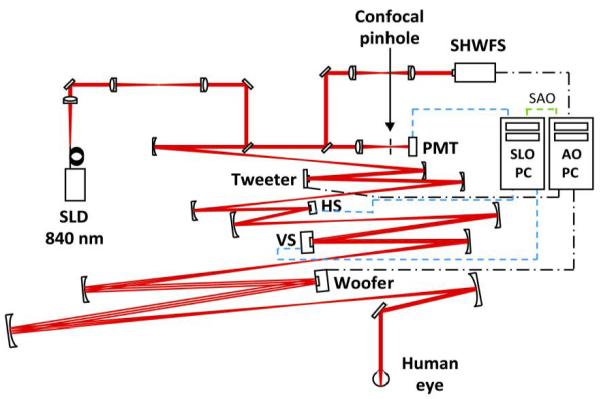
Schematic diagram of the AOSLO [25] that consists of a Shack-Hartmann wavefront sensor (SHWFS), a 52-actuator woofer mirror (Mirao 52-e, Imagine Eyes, Inc., France), and a 140-actuator tweeter mirror (Multi-DM MEMS mirror, Boston Micromachines Inc., Cambridge, MA), all in pupil conjugate planes. 840 nm light (superluminescent diode (SLD); Superlum, Ireland) enters the eye’s pupil through a maximum diameter of 8 mm and is scanned (vertical scanner, VS; horizontal scanner, HS) over a 1.5 × 1.5 deg patch of retina. The reflected light is descanned as it propagates back through the system and ~20% is diverted to the SHWFS while the remaining light is focused through a 75 micron confocal pinhole (1.4′, ~1.6 X the width of the Airy disk with an 8 mm pupil) to a photomultiplier tube (PMT) for retinal imaging. One PC performs wavefront sensing and mirror control (AO PC), a second PC acquires and records retinal image sequences (SLO PC). The PCs operate independently during wavefront sensor based control but must communicate during sensorless control (SAO). An open loop correction of lower order aberrations (primarily defocus) is placed on the woofer mirror with the SHWFS prior to initiating closed loop correction with both control methods.
The AOSLO is a dual-mirror system that employs a ‘woofer’ (Mirao 52-e, Imagine Eyes, Inc., France) to correct lower order aberrations and a ‘tweeter’ (MEMS) to correct higher order aberrations [25]. (This woofer-tweeter arrangement is required since the MEMS mirror alone lacks sufficient stroke to correct individuals with significant refractive error [27].) Prior to initiating adaptive optics control on the MEMS mirror, we used a Shack-Hartmann wavefront sensor to drive the correction of lower order aberrations (primarily defocus) with the ‘woofer’ mirror. The ‘woofer’ mirror was then held static while sensorless or wavefront sensor based control was implemented dynamically on the ‘tweeter’ mirror.
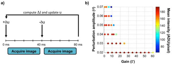
For each iteration, k, an image quality metric (ΔJk) was computed by taking the difference in the mean retinal image frame intensity after adding, and then subtracting, a random perturbation (δuik) to the control signal (uik) of each of the i actuators (Fig. 2a.). Thus, each iteration consisted of two image frames, each obtained immediately following a mirror update. Both mirrors were then held fixed over the duration of the acquired frame (Fig. 2a). The random perturbation was drawn with a uniform probability over the range -σ to σ. The actuator control signals for the next iteration were then determined by:
| (1) |
where Γ is a gain parameter that determines the amount of voltage change applied in response to the observed intensity difference. Optimal performance of the SPGD algorithm requires careful pairing of these control parameters (Fig. 2b). The gain (Γ) and perturbation (σ) amplitudes empirically determined to produce the highest image quality were similar in both model and human eyes and were also consistent with predictions from simulations.
Fig. 2.
Wavefront sensorless control algorithm details. a. Correction timeline for one iteration of sensorless control. AOSLO frames are acquired after adding, and then subtracting, a set of random perturbations (δu) to the voltage signals (u) of the 140 MEMS mirror actuators. The voltage signals (u) for the next iteration are updated by adding the perturbation (δu) in proportion to the difference in the mean intensity of the two image frames (ΔJ). Exposure of the AOSLO image frames occur over 35 msec centered within each 40 msec interval (leaving a buffer for repositioning and settling of the vertical scanner between frames) and all required calculations and mirror control occur within the first 3 msec at the start of each interval. b. Optimal sensorless adaptive optics performance requires careful pairing of the SPGD control parameters. Mean image intensity after convergence for a model eye is displayed as a function of the gain (Γ) and perturbation (σ) amplitudes. Warmer colors denote higher intensities and cooler colors denote lower intensities. Similar behavior was observed in human eyes for low perturbation amplitudes, with Γ = 40-60 and σ = 0.02-0.03 generally providing the best correction with reasonable convergence times.
Since this implementation required two retinal image frames per iteration (Fig. 2a.), the sensorless correction rate was half of the AOSLO’s imaging rate (12.5 Hz). While we implemented sensorless control on only one of the AOLSO’s mirrors, it is straightforward to extend the SPGD sensorless control method to both mirrors for future implementation on dual-mirror systems. This could be achieved either sequentially or simultaneously by employing methods to decouple the mirrors’ modal spaces similar to those already in use with simultaneous dual-mirror systems [25,28].
2.2 Wavefront sensor based control and non-common path error calibration
Wavefront sensor based control used a simple integrator (gain = 0.5) and a direct slope algorithm [29] to control the tweeter mirror (MEMs) at a rate of 10.5 Hz. This rate was predominantly determined by the wavefront sensor camera exposure and frame readout times (Rolera-XR, QImaging, Surrey, British Columbia). Sensorless adaptive optics allowed measurement and calibration of the non-common path errors between the wavefront sensor and imaging arms of the AOSLO. Calibration was accomplished by performing sensorless correction on a static model eye (consisting of a lens with a black matte reflecting surface in the nominal focal plane), and then using the Shack-Hartmann spot positions recorded during this empirically corrected state as the reference positions for subsequent wavefront sensor based correction. The rms wavefront error of the non-common path error obtained in this manner was 0.05 microns over the system pupil, and was dominated by defocus (0.04 microns). Figure 3 shows the result of this calibration in the model eye: before calibration, the sensorless method outperformed wavefront sensor based control, while both methods performed comparably after calibration. This calibration for non-common path errors ensured that the comparatively good performance of sensorless adaptive optics we observed was not due to suboptimal wavefront sensor based control or factors such as misalignment of the confocal pinhole.
Fig. 3.
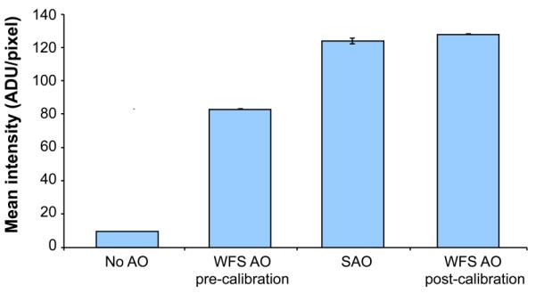
Sensorless adaptive optics control performance and non-common path error correction for wavefront sensor based adaptive optics in a model eye. Image intensities were 50% higher with sensorless control (SAO) than with traditional wavefront sensor based control (WFS AO pre-calibration). After using sensorless adaptive correction to calibrate for non-common path errors between the PMT and SHWFS (total rms wavefront error ~0.05 microns over the system pupil), the performance of wavefront sensor based control (WFS AO post-calibration) improved to the level of sensorless control. Error bars are ±1 standard deviation of the mean image frame intensity after convergence. Note that absolute intensity cannot be compared with that in Fig. 2b. due to different adjustments of the PMT gain between the two data sets.
2.3 Subjects
Sensorless and wavefront sensor based AOSLO corrections were tested and compared in five human subjects with no known ocular pathology. All human subjects research adhered to the tenets of the Declaration of Helsinki and the study protocol was approved by the University of Houston’s Committee for the Protection of Human Subjects. An informed consent was obtained for each human subject prior to participation. Subjects ranged in age from 32 to 40 years and refractive errors were as follows: S.30: −1.50 Dsph, −1.00 Dcyl; S.31: 0.50 Dsph, −0.25 Dcyl; S.49: 0.75 Dsph; S.62: 1.5 Dsph, −0.75 Dcyl; S.74: −2.25 Dsph, −0.25 Dcyl.
2.4 Experimental comparison of wavefront sensorless and wavefront sensor based control
Multiple image sequences 30-100 seconds in length were first acquired at a rate of 25 Hz through each subject’s natural, undilated pupil (3-6 mm diameter) with both sensorless and wavefront sensor based control. The subject’s pupil was then dilated with 1 drop of 2.5% phenylephrine and 1 drop of 1% tropicamide and imaging was repeated through the full system pupil (8 mm). A static, lower order aberration correction was implemented with the system’s ‘woofer’ mirror (Mirao 52-e) prior to initiation of closed-loop adaptive optics correction in all cases. A blink rejection algorithm prevented the mirror from updating during sensorless control if the intensity in sequential retinal image frames differed by more than 50%. Averaged retinal images were created by registering and averaging 25 representative frames for each subject in each condition. Frames with the highest mean intensity and least eye movement were selected for registration. The relative performance of each control method was assessed by subjectively examining the average images. Performance was also assessed objectively by comparing the mean image intensity as a function of time and the radially-averaged power spectra of the averaged retinal images.
3. Results
3.1 Comparison of AOSLO image quality with sensorless and wavefront sensor based control
Figures 4 & 5 show that the retinal images acquired with sensorless control in living human eyes are of comparable quality to those obtained with conventional wavefront sensor based control in the same optical system. Typically, adaptive optics imaging is performed through dilated pupils because the most significant gains in image quality occur with large pupils. Figure 4 shows representative images for three subjects with a dilated pupil (8 mm) following sensorless and wavefront sensor based control. Image quality is subjectively similar, although convergence was slower and mean image intensity was typically somewhat lower (in 4 of 5 subjects) with sensorless control. Despite the lower image intensities and slower convergence, normalized image power spectra after sensorless adaptive optics were equal to or greater than those obtained with wavefront sensor based control. (The increase was not an artifact of the differing mean intensities in the two methods as it was an order of magnitude larger than expected based on the difference in the signal to noise ratio in the two conditions.)
Fig. 4.
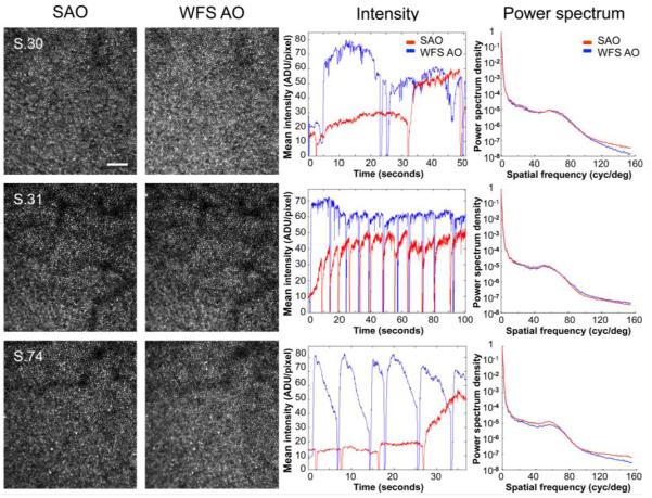
Comparison of sensorless and wavefront sensor based control for AOSLO imaging through dilated (8 mm) pupils in 3 representative subjects. Images after sensorless adaptive optics (SAO, 1st column) and wavefront sensor based adaptive optics (WFS AO, 2nd column) were similar in all subjects. Images were acquired at ~1 deg eccentricity and are shown at the same scale. Scale bar is 10′. The center of the fovea is approximately located in the bottom left corner. Despite typically lower image intensities and somewhat slower convergence (3rd column), normalized image power spectra after sensorless control (red) were equal to or greater than those obtained with wavefront sensor based control (blue) (4th column). (The sharp dips in the mean intensity traces are due to blinks or partial blinks. The gradual drop in intensity after recovering from blinks with WFS AO, such as in S.74, likely reflects instability or break-up of tear film.) Note that the PMT gain was adjusted separately for each subject and pupil size, precluding direct comparison of absolute intensity values across subjects or between undilated and dilated pupils. Gain and perturbation amplitudes (Γ, σ) were as follows: S.30, (55, 0.02); S.31, (40, 0.03); S.74, (60, 0.02).
Fig. 5.
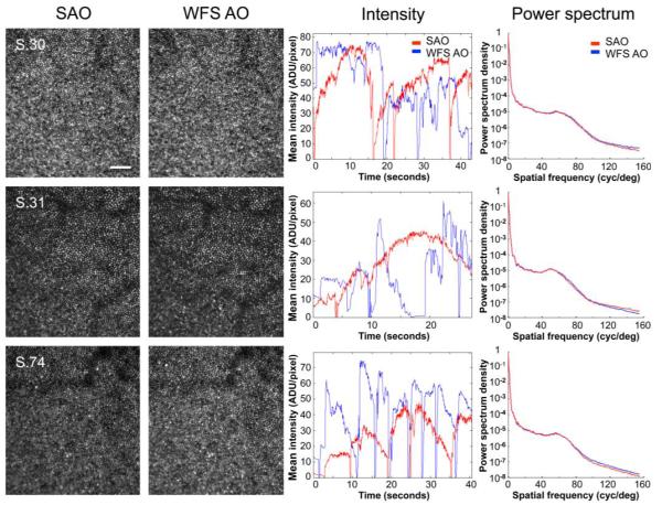
Comparison of sensorless and wavefront sensor based control for AOSLO imaging through natural, undilated pupils (S.30, 6 mm; S.31, 4 mm; S.74, 6 mm) in the same 3 representative subjects. Images after sensorless adaptive optics (SAO, 1st column) and wavefront sensor based adaptive optics (WFS AO, 2nd column) were subjectively similar for all subjects. Images were acquired at ~1 deg eccentricity and are shown at the same scale. Scale bar is 10′. The center of the fovea is approximately located in the bottom left corner. Both image intensity (3rd column), and relative spectral power density (4th column) after sensorless control (red) compare favorably with wavefront sensor based control (blue). The irregularity of the mean intensity traces with wavefront sensor based control likely reflects 1. difficulties in obtaining an accurate wavefront sensor based control signal with smaller, fluctuating, pupils, and 2. tear film instabilities or break-up. (The sharp dips in the mean intensity traces are due to blinks or partial blinks.) Note that the PMT gain was adjusted separately for each subject and pupil size, precluding direct comparison of absolute intensity values across subjects or between undilated and dilated pupils. Gain and perturbation amplitudes (Γ, σ) for each subject were as follows: S.30, (60, 0.02); S.31, (50, 0.02); S.74, (60, 0.02).
The good performance of sensorless adaptive optics is also evident when imaging through natural, undilated pupils (e.g., 4-6 mm). In this case, sensorless control performs as well as wavefront sensor based control in terms of subjective image quality and mean image intensity (shown in Fig. 5). Results for all subjects were similar, with sensorless correction even allowing individual photoreceptors to be resolved in one subject whose small natural pupil (3 mm) precluded successful wavefront sensor based correction (presumably due to the difficulty in obtaining an accurate mirror control signal from a severely reduced set of Shack-Hartmann spots, Fig. 6). The robust performance of sensorless adaptive optics for natural optics and pupils that underfill the AOSLO’s entrance aperture (8 mm) suggests that sensorless methods may require less precise head stabilization and reduce the need for pharmacological pupil dilation, features that would be highly advantageous in a clinically deployed system.
Fig. 6.
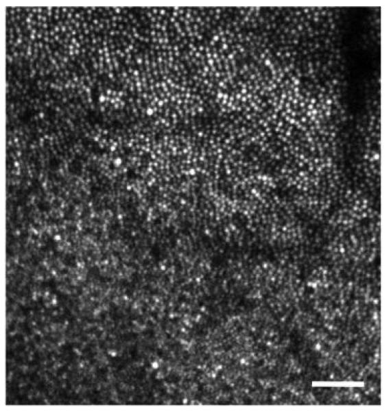
Sensorless adaptive optics allowed clear images of individual photoreceptors to be acquired in one subject (S.62) when the pupil was sufficiently small (3 mm) as to prevent wavefront sensor based correction. Location and image details are the same as for Figs. 4 & 5. Scale bar is 10′.
Figures 4 & 5 demonstrate that images taken with sensorless control are of comparable quality to those acquired with wavefront sensor based control despite typically having reduced image intensities (with dilated pupils) and requiring increased time to reach the best correction. Normalized image power spectra, which are related to the square of the contrast at each spatial frequency, are similar in both methods. Image quality with sensorless and wavefront sensor based control was compared more quantitatively by plotting the contrast ratio for the averaged images acquired with both control methods as a function of spatial frequency in all eyes (Fig. 7). When imaging through natural, undilated pupils (Fig. 7a.), image contrast, on average, was not significantly different with sensorless than with wavefront sensor based control. However, when imaging through dilated pupils (Fig. 7b.), image contrast tended to be higher with sensorless than with wavefront sensor based control, and this improvement was significant, on average. That sensorless control could produce higher contrast, but lower intensity, images reflects the tendency of the sensorless method, as implemented here, to generate light distributions with tight central cores often accompanied by broader ‘wings’ or halos. (This tendency was verified by observing the aerial double pass pointspread function during sensorless correction with a model eye).
Fig. 7.
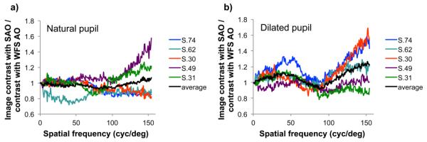
Ratio of the image contrast for averaged retinal images acquired with the sensorless control method to those acquired with traditional wavefront sensor based control in 5 subjects when imaging through a. natural and b. dilated pupils. Dilated pupil size was 8 mm, undilated pupil size was approximately: S.30, 6 mm; S.31, 4 mm; S.49, 6 mm; S.62, 4 mm; S.74, 6 mm. Contrast ratios were calculated by taking the square root of the ratio of the normalized image power spectra. With natural pupils the contrast ratio averaged across subjects (black line) is not significantly different from 1, indicating that sensorless control yielded images of comparable contrast to those obtained with wavefront sensor based control. However when imaging through dilated pupils the contrast ratio averaged across subjects was greater than 1 at most spatial frequencies, indicating higher contrast with sensorless control. The average contrast improvement with sensorless control approached 25% at the highest spatial frequencies.
Since the image quality metric in our sensorless control implementation is the light transmitted through the confocal pinhole averaged over the image frame duration (35ms), the size of the confocal pinhole places a limit on the maximum optical quality that can be achieved. Once the optical correction is sufficiently good so that all (or nearly all) of the light is focused through the pinhole, further improvements in optical quality will no longer result in increases in light intensity, and will therefore not be effective at driving the sensorless algorithm. We used a confocal pinhole subtending 1.4′ at the retina which is ~1.6 X the Airy disk diameter at 840 nm with an 8 mm pupil. The good performance we achieved with this relatively large pinhole diameter suggests that even greater gains in contrast might be achievable with smaller confocal pinholes [26].
4. Discussion
4.1 Challenges in implementing wavefront sensorless adaptive optics in the human eye
The living human eye poses several unique characteristics that make it challenging to successfully implement wavefront sensorless adaptive optics techniques. Typically, wavefront sensorless correction methods have been implemented in situations where aberrations and the specimen being imaged are essentially static (e.g., in microscopy) [19, 22-24]. This is quite unlike the situation in the living eye, where aberrations and tear film quality are inherently dynamic [30] and eye movements create constant motion of the retina with respect to the imaging sensor. The dynamics of the eye’s aberrations are exacerbated by the difficulty of stabilizing patients’ pupils with respect to the optical system, while eye movements create the possibility that differences in intensity due to the spatial structure of the retina could create spurious differences in the intensity metric used for the sensorless control signal. These dynamics are especially problematic given the relatively large number of iterations that are required for correction with sensorless methods. Blinking presents an additional challenge and requires an algorithm that is insensitive to intermittent signal loss. Despite these challenges, we have demonstrated that sensorless control can be successfully implemented in the living human eye with performance comparable to that achieved with wavefront sensor based control. Importantly, our sensorless adaptive optics implementation required no changes to the hardware or optical configuration of the existing AOSLO. Therefore, our results should be easily replicable in other confocal systems (or non-confocal adaptive optics systems where double-pass pointspread function imaging is enabled) with only relatively simple software changes in the mirror control algorithm. Future increases in speed and performance may be achieved with a number of further hardware and software modifications, for example by using the time averaged PMT signal directly and integrating over a shorter interval of time (using smaller frames, or fractions of frames), using a smaller number of mirror modes to control the mirror (rather than the 140 individual actuators), or by using an adjustable pinhole or detector with flexible integration area. The latter strategy may also be beneficial when correcting highly aberrated eyes in a wavefront sensorless system, as the pinhole size (or detector integration area) places a minimum requirement on optical quality to allow sufficient intensity to initiate correction. (An initial scan through focus is another potential solution.)
The sensorless adaptive optics implementation we present here has the additional property that it automatically focuses on the most reflective retinal layer. While this may be advantageous in photoreceptor imaging or fluorescence imaging, it presents a further challenge for confocal applications that require imaging different retinal layers. One could imagine several future strategies that, if pursued, might allow sensorless control to be compatible with optical sectioning applications. For example, with a rapid enough mirror, one could alternate frames used for sensorless control with imaging frames containing an appropriate defocus increment. It may also be possible to run sensorless control with reduced gain to maintain focus at a local intensity maximum corresponding to a non-photoreceptor layer.
4.2 Advantages of wavefront sensorless adaptive optics in the human eye
The results shown in Figs. 4-7 indicate that, despite the significant challenges, sensorless adaptive optics is a viable method in the living human eye. Despite lower mean image intensities (in 4 of our 5 subjects), sensorless correction produced retinal images with higher contrast in dilated pupils. Sensorless control could also be beneficial with small or undilated pupils and may succeed in individuals for whom wavefront sensing is not possible (Fig. 6). This suggests that sensorless control may be particularly valuable in a clinical system or for patients with ocular pathology (such as cataracts or keratoconus), for whom traditional wavefront sensor based adaptive optics is difficult. Sensorless adaptive optics has additional advantages. First, sensorless control has the potential to achieve better optical quality than wavefront sensor based control because it is insensitive to wavefront sensor noise and infidelity (including the mirror ‘edge artifact’ [31]), and contains no non-common path errors. The automatic correction of system aberrations and absence of non-common path errors is a significant benefit -– not only can it result in higher optical quality, but it confers an insensitivity to alignment errors, which would be particularly advantageous in clinically deployed systems. Moreover, sensorless adaptive optics enables straightforward, objective measurement and compensation of the non-common path errors inherent in wavefront sensor based systems (Fig. 3). Second, sensorless control requires less light for aberration correction and retinal imaging since no light is diverted from the image for wavefront sensing and all of the light returning from the eye is focused to only a single spot, rather than split up into hundreds of spots (as in a typical Shack-Hartmann wavefront sensor). Lower light levels might be especially advantageous when imaging in light-sensitive patients, such as those suffering from rhodopsin disorders in retinitis pigmentosa [32], and for applications, such as autofluoresence imaging [11], where sensorless control may confer additional benefit by allowing direct optimization of the fluorescence signal. Elimination of the wavefront sensor’s “laser beacon” would also prevent any potential visual interference when presenting visual stimuli in functional experiments, enabling the full realization of adaptive optics’ potential to uncover the most sensitive retinal and neural limits on vision. Lastly, since sensorless adaptive optics does not require a wavefront sensor, a sensorless system would be simpler, cheaper, and more robust than current adaptive optics retinal imaging systems.
4. Conclusion
We have established sensorless adaptive optics as a viable alternative to traditional wavefront sensor based adaptive optics for imaging the living human retina. Sensorless control is effective in dilated, as well as small or undilated, pupils and may succeed in individuals for whom wavefront sensing is not possible. Sensorless adaptive optics has the potential to achieve better optical quality than traditional wavefront sensor based control, with lower light levels, and may allow simpler, more robust systems. One of the current challenges in implementing wavefront sensorless adaptive optics in the human eye (given the temporal dynamics inherent in the eye’s aberrations which are not typically present in microscopy and other photonic engineering applications) is its relatively slow convergence speed. However, even in this basic implementation, the retinal images acquired with sensorless adaptive optics are comparable to those obtained with wavefront sensor based control. Future refinements, such as modal control, may reduce convergence time and result in even greater optical gains. Ultimately, sensorless adaptive optics may enable new cellular-level vision experiments that further our understanding of the link between retinal anatomy and visual function. It may also allow routine cellular-level imaging in a larger number of normal and diseased eyes, allowing us to better understand and to earlier detect, monitor, and treat retinal diseases.
Acknowledgements
This work was supported by National Institutes of Health Grants RO1 EY019069 and P30 EY07551, the Texas Advanced Research Program under Grant No. G096152, and the University of Houston College of Optometry. Single mirror wavefront sensor based control software was partially developed by Alfredo Dubra-Suarez, funded by a Career Award from the Burroughs Wellcome Fund, and Kamran Ahmad, with funding from NIH grant BRP-EY01437 and the NSF Science and Technology Center for Adaptive Optics.
Footnotes
OCIS codes: (000.3860) Mathematical methods in physics; (110.1080) Active or Adaptive optics; (330.4460) Ophthalmic optics and devices.
References and links
- 1.Liang J, Williams DR, Miller DT. Supernormal vision and high-resolution retinal imaging through adaptive optics. J. Opt. Soc. Am. A. 1997;14(11):2884–2892. doi: 10.1364/josaa.14.002884. [DOI] [PubMed] [Google Scholar]
- 2.Roorda A, Williams DR. The arrangement of the three cone classes in the living human eye. Nature. 1999;397(6719):520–522. doi: 10.1038/17383. [DOI] [PubMed] [Google Scholar]
- 3.Hofer H, Singer B, Williams DR. Different sensations from cones with the same photopigment. J. Vis. 2005;5(5):444–454. doi: 10.1167/5.5.5. [DOI] [PubMed] [Google Scholar]
- 4.Makous W, Carroll J, Wolfing JI, Lin J, Christie N, Williams DR. Retinal microscotomas revealed with adaptive-optics microflashes. Invest. Ophthalmol. Vis. Sci. 2006;47(9):4160–4167. doi: 10.1167/iovs.05-1195. [DOI] [PubMed] [Google Scholar]
- 5.Sincich LC, Zhang Y, Tiruveedhula P, Horton JC, Roorda A. Resolving single cone inputs to visual receptive fields. Nat. Neurosci. 2009;12(8):967–969. doi: 10.1038/nn.2352. [DOI] [PMC free article] [PubMed] [Google Scholar]
- 6.Rossi EA, Roorda A. The relationship between visual resolution and cone spacing in the human fovea. Nat. Neurosci. 2010;13(2):156–157. doi: 10.1038/nn.2465. [DOI] [PMC free article] [PubMed] [Google Scholar]
- 7.Jonnal RS, Besecker JR, Derby JC, Kocaoglu OP, Cense B, Gao W, Wang Q, Miller DT. Imaging outer segment renewal in living human cone photoreceptors. Opt. Express. 2010;18(5):5257–5270. doi: 10.1364/OE.18.005257. [DOI] [PMC free article] [PubMed] [Google Scholar]
- 8.Roorda A, Romero-Borja F, Donnelly Iii W, Queener H, Hebert T, Campbell M. Adaptive optics scanning laser ophthalmoscopy. Opt. Express. 2002;10(9):405–412. doi: 10.1364/oe.10.000405. [DOI] [PubMed] [Google Scholar]
- 9.Hermann B, Fernández EJ, Unterhuber A, Sattmann H, Fercher AF, Drexler W, Prieto PM, Artal P. Adaptive-optics ultrahigh-resolution optical coherence tomography. Opt. Lett. 2004;29(18):2142–2144. doi: 10.1364/ol.29.002142. [DOI] [PubMed] [Google Scholar]
- 10.Zhang Y, Cense B, Rha J, Jonnal RS, Gao W, Zawadzki RJ, Werner JS, Jones S, Olivier S, Miller DT. High-speed volumetric imaging of cone photoreceptors with adaptive optics spectral-domain optical coherence tomography. Opt. Express. 2006;14(10):4380–4394. doi: 10.1364/OE.14.004380. [DOI] [PMC free article] [PubMed] [Google Scholar]
- 11.Gray DC, Merigan W, Wolfing JI, Gee BP, Porter J, Dubra A, Twietmeyer TH, Ahamd K, Tumbar R, Reinholz F, Williams DR. In vivo fluorescence imaging of primate retinal ganglion cells and retinal pigment epithelial cells. Opt. Express. 2006;14(16):7144–7158. doi: 10.1364/oe.14.007144. [DOI] [PubMed] [Google Scholar]
- 12.Hunter JJ, Masella B, Dubra A, Sharma R, Yin L, Merigan WH, Palczewska G, Palczewski K, Williams DR. Images of photoreceptors in living primate eyes using adaptive optics two-photon ophthalmoscopy. Biomed. Opt. Express. 2011;2(1):139–148. doi: 10.1364/BOE.2.000139. [DOI] [PMC free article] [PubMed] [Google Scholar]
- 13.Carroll J, Neitz M, Hofer H, Neitz J, Williams DR. Functional photoreceptor loss revealed with adaptive optics: an alternate cause of color blindness. Proc. Natl. Acad. Sci. U.S.A. 2004;101(22):8461–8466. doi: 10.1073/pnas.0401440101. [DOI] [PMC free article] [PubMed] [Google Scholar]
- 14.Wolfing JI, Chung M, Carroll J, Roorda A, Williams DR. High-resolution retinal imaging of cone-rod dystrophy. Ophthalmology. 2006;113(6):1014–1019. doi: 10.1016/j.ophtha.2006.01.056. [DOI] [PubMed] [Google Scholar]
- 15.Talcott KE, Ratnam K, Sunquist SM, Lucero AS, Lujan BJ, Tao W, Porco TC, Roorda A, Duncan JL. Longitudinal study of cone photoreceptors during retinal degeneration and in response to ciliary neurotrophic growth factor. Invest. Ophthalmol. Vis. Sci. 2011;52(5):2219–2226. doi: 10.1167/iovs.10-6479. [DOI] [PMC free article] [PubMed] [Google Scholar]
- 16.Ooto S, Hangai M, Sakamoto A, Tsujikawa A, Yamashiro K, Ojima Y, Yamada Y, Mukai H, Oshima S, Inoue T, Yoshimura N. High-resolution imaging of resolved central serous chorioretinopathy using adaptive optics scanning laser ophthalmoscopy. Ophthalmology. 2010;117(9):1800.e1–1809.e2. doi: 10.1016/j.ophtha.2010.01.042. [DOI] [PubMed] [Google Scholar]
- 17.Kitaguchi Y, Kusaka S, Yamaguchi T, Mihashi T, Fujikado T. Detection of photoreceptor disruption by adaptive optics fundus imaging and Fourier-domain optical coherence tomography in eyes with occult macular dystrophy. Clin. Ophthalmol. 2011;5:345–351. doi: 10.2147/OPTH.S17335. [DOI] [PMC free article] [PubMed] [Google Scholar]
- 18.Doble N. High-resolution, in vivo retinal imaging using adaptive optics and its future role in ophthalmology. Expert Rev. Med. Devices. 2005;2(2):205–216. doi: 10.1586/17434440.2.2.205. [DOI] [PubMed] [Google Scholar]
- 19.Booth MJ. Adaptive optics in microscopy. Philos. Transact. A Math. Phys. Eng. Sci. 2007;365(1861):2829–2843. doi: 10.1098/rsta.2007.0013. [DOI] [PubMed] [Google Scholar]
- 20.Biss DP, Webb RH, Yaopeng Z, Bifano TG, Zamiri P, Lin CP. An adaptive optics biomicroscope for mouse retinal imaging. Proc. SPIE. 2007;6467:646703–646708. [Google Scholar]
- 21.Zommer S, Ribak EN, Lipson SG, Adler J. Simulated annealing in ocular adaptive optics. Opt. Lett. 2006;31(7):939–941. doi: 10.1364/ol.31.000939. [DOI] [PubMed] [Google Scholar]
- 22.Vorontsov MA. Decoupled stochastic parallel gradient descent optimization for adaptive optics: integrated approach for wave-front sensor information fusion. J. Opt. Soc. Am. A. 2002;19(2):356–368. doi: 10.1364/josaa.19.000356. [DOI] [PubMed] [Google Scholar]
- 23.Fienup JR, Miller JJ. Aberration correction by maximizing generalized sharpness metrics. J. Opt. Soc.Am. A. 2003;20(4):609–620. doi: 10.1364/josaa.20.000609. [DOI] [PubMed] [Google Scholar]
- 24.Débarre D, Botcherby EJ, Watanabe T, Srinivas S, Booth MJ, Wilson T. Image-based adaptive optics for two-photon microscopy. Opt. Lett. 2009;34(16):2495–2497. doi: 10.1364/ol.34.002495. [DOI] [PMC free article] [PubMed] [Google Scholar]
- 25.Li C, Sredar N, Ivers KM, Queener H, Porter J. A correction algorithm to simultaneously control dual deformable mirrors in a woofer-tweeter adaptive optics system. Opt. Express. 2010;18(16):16671–16684. doi: 10.1364/OE.18.016671. [DOI] [PMC free article] [PubMed] [Google Scholar]
- 26.Wilson T. The role of the pinhole in confocal imaging systems. In: Pawley JB, editor. Handbook of Biological Confocal Microscopy. Plenum Press; New York: 1995. [Google Scholar]
- 27.Doble N, Miller DT, Yoon G, Williams DR. Requirements for discrete actuator and segmented wavefront correctors for aberration compensation in two large populations of human eyes. Appl. Opt. 2007;46(20):4501–4514. doi: 10.1364/ao.46.004501. [DOI] [PMC free article] [PubMed] [Google Scholar]
- 28.Zou W, Qi X, Burns SA. Woofer-tweeter adaptive optics scanning laser ophthalmoscopic imaging based on Lagrange-multiplier damped least-squares algorithm. Biomed. Opt. Express. 2011;2(7):1986–2004. doi: 10.1364/BOE.2.001986. [DOI] [PMC free article] [PubMed] [Google Scholar]
- 29.Jiang W, Li H. Schulte-in-den-Baeumen JJ, Tyson RK, editors. Hartmann-Shack Wavefront Sensing and Control Algorithm. Adaptive Optics and Optical Structures. Proceedings of the SPIE. 1990;1271:82–93. SPIE. [Google Scholar]
- 30.Hofer H, Artal P, Singer B, Aragón JL, Williams DR. Dynamics of the eye’s wave aberration. J. Opt.Soc. Am. A. 2001;18(3):497–506. doi: 10.1364/josaa.18.000497. [DOI] [PubMed] [Google Scholar]
- 31.Porter J, Queener H, Lin J, Thorne K, Awwal A, editors. Adaptive Optics for Vision Science: Principles, Practices, Design, and Applications. John Wiley and Sons, Inc.; New Jersey: 2006. Ch. 5. [Google Scholar]
- 32.Cideciyan AV, Jacobson SG, Aleman TS, Gu D, Pearce-Kelling SE, Sumaroka A, Acland GM, Aguirre GD. In vivo dynamics of retinal injury and repair in the rhodopsin mutant dog model of human retinitis pigmentosa. Proc. Natl. Acad. Sci. U.S.A. 2005;102(14):5233–5238. doi: 10.1073/pnas.0408892102. [DOI] [PMC free article] [PubMed] [Google Scholar]


