Abstract
The biomechanical model of glaucoma considers intraocular pressure-related stress and resultant strain on load bearing connective tissues of the optic nerve and surrounding peripapillary sclera as one major causative influence that effects cellular, vascular, and axonal components of the optic nerve. By this reasoning, the quantification of variations in the microstructural architecture and macromechanical response of scleral shells in glaucomatous compared to healthy populations provides an insight into any variations that exist between patient populations. While scleral shells have been tested mechanically in planar and pressure-inflation scenarios the link between the macroscopic biomechanical response and the underlying microstructure has not been determined to date. A potential roadblock to determining how the microstructure changes based on pressure is the ability to mount the spherical scleral shells in a method that does not induce unwanted stresses to the samples (for instance, in the flattening of the spherical specimens), and then capturing macroscopic and microscopic changes under pressure. Often what is done is a macroscopic test followed by sample fixation and then imaging to determine microstructural organization. We introduce a novel device and method, which allows spherical samples to be pressurized and macroscopic and microstructural behavior quantified on fully hydrated ocular specimens. The samples are pressurized and a series of markers on the surface of the sclera imaged from several different perspectives and reconstructed between pressure points to allow for mapping of nonhomogenous strain. Pictures are taken from different perspectives through the use of mounting the pressurization scheme in a gimbal that allows for positioning the sample in several different spherical coordinate system configurations. This ability to move the sclera in space about the center of the globe, coupled with an upright multiphoton microscope, allows for collecting collagen, and elastin signal in a rapid automated fashion so the entire globe can be imaged.
Keywords: microstructure, extracellular matrix, two-photon, sclera, glaucoma, multiphoton
1 Introduction
According to the World Health Organization, glaucoma is estimated to affect 80 × 106 people by 2020 worldwide, making it the second leading cause of blindness [1]. The diagnosis and treatment strategies for primary open angle glaucoma (POAG) are still imperfect, since little is currently known regarding the impact of variations in optic disc anatomy and susceptibility to glaucoma.
In the pathogenesis of glaucomatous optic neuropathy, the damage and loss of retinal ganglion cell (RGC) function in the optic nerve head (ONH) has been believed to be important in the vision loss associated with glaucoma [2–4]. The lamina cribrosa (LC) and peripapillary sclera (PS) have been suggested to be the site where damage to nerve fibers occurs [5]. Many researchers have agreed on the critical role played by mechanical forces acting in the region of ONH in the progression of the disease [3,4].
Experimental investigations of the biomechanical response of LC and PS from animals have been conducted by several researchers [6–11]. Most recently, 2D mappings of mechanical responses (i.e., displacement, stress, and strain) and material properties (i.e., tangent modulus, structural stiffness, and preferred collagen fiber orientation) of monkey ocular tissues under various intraocular pressures (IOP) have been reported [10]. To determine the relationship between these macroscopic observations and the ocular extracellular matrix (ECM) organization, the microstructure of ocular tissues have been fixed after testing and/or experimentally back-fit using computational models [10]. Preliminary computational modeling of the biomechanical behavior of the human LC and PS has suggested that the laminar connective tissues may experience greater IOP-related strain in eyes with larger and/or more oval optic discs [12], and that the peripapillary scleral structure, especially the thickness, may have an important effect on the mechanical response of LC and PS [13]. Additionally, mathematical models of the LC have suggested that ONHs with larger scleral canals and/or thinner lamina undergo more IOP-induced deformation [14]. Thus, the larger optic discs commonly found in patients of African descent and Hispanic ethnicity may experience greater strain at similar IOP. The ability to capture macroscopic behavior and microstructural alterations under pressure on hydrated, nonfixed samples may provide unique insight into the nonhomogeneous variations in the PS and LC and the underlying microstructural components responsible for higher susceptibility in populations at-risk for POAG.
We have developed a novel micro-opto-mechanical device, referred to as the Ocugimbal, which is capable of assessing the pressure dependent macroscopic and microscopic response of posterior ocular tissues. This device is centered on a gimbal-based motion control system, which rotates a posterior pressure-inflation setup in a spherical coordinate system, thus allowing simple quantification of the heterogeneous macroscopic and microscopic properties of the PS and LC. The Ocugimbal was designed to work with an advanced intravital multiphoton microscope at the University of Arizona, thus allowing nondestructive quantification of ECM microstructure at various IOPs using nonlinear optical microscopy (the second harmonic generation (SHG) of collagen and the two-photon excitation fluorescence (2PEF) of elastin). The purpose of this paper is to demonstrate the ability of the Ocugimbal to experimentally measure the macroscopic biomechanical response and corresponding IOP-dependent ECM microstructure of the PS and LC.
2 Materials and Methods
Overall, specimens are mounted onto an angled pedestal and clamped around the perimeter with a flanged annulus to allow for leak-free pressurization. The pedestal/clamp assembly is coupled to one manually rotating axis and two automated axes that cover an entire range of movement over an angle of 2π. The pressurization line connected to the pedestal is connected to a syringe pump and pressure transducer and correspondingly connected to a data acquisition board, controllers, and personal computer. A window in the side of the testing bath allows the macroscopic biomechanical behavior of posterior poles to be assessed. The macroscopic mechanical deformation is tracked by following markers placed on the surface of the sclera between stress states. After macroscopic testing, the device is placed under the microscope and microstructure quantified under the same pressures as macroscopic testing, thus providing a link between the microstructural and macroscopic behavior.
2.1 Ocugimbal Device
Mechanical design was performed with SolidWorks 2010 (Concord, MA) and motion control programming was performed with LABVIEW 8.5.1 (Austin, TX). Samples from 5 mm to 25 mm in diameter can be mounted. This range of sizes can be accommodated through changing a single part in the assembly. The general mounting scheme for pressurization may be seen in Fig. 1 and is based on a previously used design [15,16]. Eyes are cut into hemispheres and mounted into the fixture with the sealing flange attached. Air bubbles are removed by cycling fluid through the assembly. The mounted eye in the pressurization assembly is placed into the gimbal shown in Fig. 2 (note the rotation axes). Axes D and F are coupled to stepper motors (Lin Engineering, Morgan Hill, CA) while axis E can be manually manipulated. With the entire gimbal assembly enclosed in a water bath, access to the underside of the pressurization fixture to attach the sprocket that allows for rotation about the ONH axis (axis D) was factored into the design. This was accomplished by the manual rotation axis (Fig. 3(C)) shows attachment of the ONH rotation sprocket). The manual rotation axis is locked after placing the pressurization fixture and corresponding sprocket into the Ocugimbal. The eye is pressurized with a syringe pump (New Era Pump Systems, Inc., Farmingdale, NY) and pressure is monitored with an inline pressure transducer (Omega Engineering, Inc, Stamford, CT). The syringe pump has an infusion rate ranging from 0.73 μl/h to 2100 ml/h with a dispensing accuracy of ±1%. The pressure of the system is monitored using a low-range pressure transducer rated from 0 to 2 psi with an accuracy of ±0.25%. The internal pressure cavity (representing the IOP) can be controlled from 0 to 60 mm Hg with an accuracy of 0.25 mm Hg.
Fig. 1.

Overall pressurization scheme for the sclera: (A) isometric cutaway view, (B) shows a side cutaway view of the mount, (C) demonstrates the ability to test different sizes scleras, (D) is the sclera, (E) is the inflow hole, (F) is the fluid exit hole, (G) is the mounting ring touching the sclera, and (H) is the mounting plate for the sclera. Scale bar is 10 mm.
Fig. 2.

Movement scheme of the gimbal: Panel (A) the assembled motion component scheme with the rotation axes, (C) is the mounted sclera, (D) is the axis for motorized rotation about the optical axis (equatorial), (E) is the manual rotation axis for installation of the sprocket for axis (D), and (F) is the motorized axis for lateral rotation (meridional). Note that as rotation occurs about (F), the (D) axis is rotated about (F), as well. Panel (B) is an isometric exploded view of the mounting scheme to the motion components. (C) is the sclera and (D) is the centerline for rotation about the optical axis.
Fig. 3.

Assembly of the sclera into the device: (A) sclera before clamping, (B) sclera after clamping, (C) attaching the sprocket for optical axis rotation, and (D) ready system for testing
The motorized axes (motion components from WM Berg, Cudahy, WI) are implemented to allow the sclera to be rotated about the ONH axis (equatorial, Fig. 2 axis D) 360 deg, while also allowing free lateral rotations (meridional, Fig. 2 axis F) up to 20 deg. Rotation about the ONH axis is implemented with a precision sprocket/chain arrangement since direct coupling of a motor with gears is not possible since the ONH axis, itself, rotates with changes in lateral angle. Through this type of arrangement, regardless of the induced meridional rotation, the motor will engage to rotate the eye about the ONH axis. The lateral rotation is done through a gear arrangement. With a change of lateral angle, the sprocket directly coupled to the eye pressurization assembly shifts, therefore, altering tension on the chain. A chain-tensioner assembly is coupled which shifts forth-and-back, based on competing tensions between the chain and an extension spring, to make sure tension in the chain remains constant, and therefore workload on the motor remains constant (see Fig. 4). Positional resolution is 0.05 deg for the lateral axis, and 0.09 deg for the optic nerve axis.
Fig. 4.
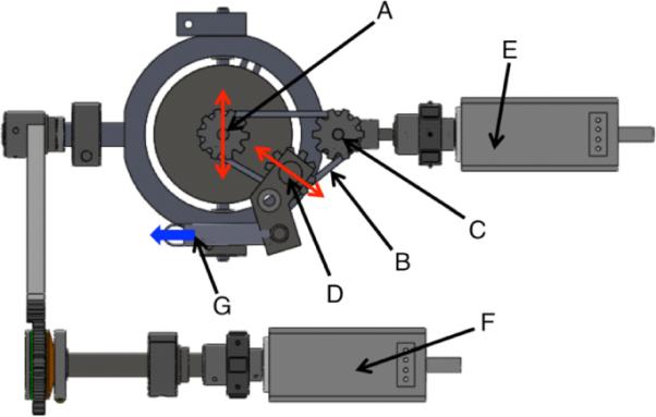
View from underneath the device showing the design scheme for maintaining proper tension on the optical axis rotation sprocket/pulley system: (A) optical axis rotation sprocket with the red arrow indicating the lateral movement induced by rotation from the lateral rotation motor, (B) pulley, (C) pulley drive from the optical axis rotation motor, and (D) tension sprocket. The arrows here indicate lateral movements that occur with lateral movement of (A). This is to keep constant tension on the belt. Tension is applied with the spring shown in (G) with the arrow indicating force (F) is the lateral rotation motor.
The motion control system is attached to a testing bath. The testing bath is heated through the use of Kapton heaters underneath the bath and a thermocouple inside the bath. These components are connected to a controller system (Omega Engineering, Inc, Stamford, CT) to allow the operator to set the temperature of the testing bath to 37±1 °C. A window in the side of the testing bath allows samples to be imaged from the side to obtain macroscopic surface strains. The system is programmed to allow the user to set a pressure for testing the sclera, which works in conjunction with the pressure transducer and syringe pump. The user can then provide any meridional and equatorial rotations within the design specifications. The entire Ocugimbal system can be seen in Fig. 5.
Fig. 5.
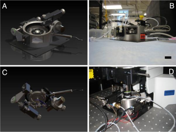
Comparisons of the renders from the solid modeling of the design (A): Overall and (C): bath hidden from underneath, (B) side-view through the macroscopic observation window, and (D) the device under the microscope. Scale bar is 25 mm.
Macroscopic behavior is captured by first placing 24 markers in eight ~45 deg equatorial and three ~15 deg meridional increments about the posterior globe. Figures 6(A) and 6(C) demonstrates marker placement as viewed from the side window of the bath and from the top. The markers are a cyanoacrylate/ceramic dust mixture. Pictures of the sclera from the side profile are taken at eight different ONH axis rotation angles while keeping the lateral axis fixed. This allows the movement of all markers to be captured at various pressurization states. For any given pressure/ONH rotation, the positions of the six side profile, and three face-on markers are recorded to reconstruct the points in postprocessing. Microscopic behavior is characterized by placing the entire setup under the multiphoton microscope, performing a meridional (lateral) rotation then performing imaging raster scans at all equatorial axis rotations until that band is imaged. Following another lateral rotation, the ONH axis is again rotated and further image acquisition occurs around all equatorial axis rotations. This is continued until images are acquired for all of the desired anatomical locations.
Fig. 6.
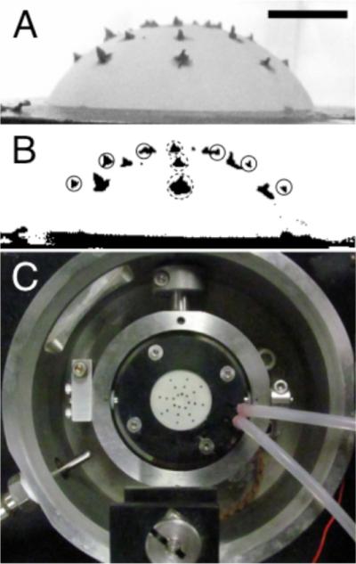
(A) A side-view of a sample through the bath window with applied markers to monitor macroscopic strain, (B) thresholded image, and (C) a top-down view of marker placement. Scale bar is 5 mm for panels A and B.
2.2 Data Processing
2.2.1 Macroscopic Strains
For the six on-edge markers (solid circles, Fig. 6(B)), a series of coordinates from the markers is obtained by locating the outer intersection of the marker with the sample from the side profile using a thresholded (Otsu method) image in NIH ImageJ. For the three out of plane markers (dotted circles, Fig. 6(B)), the geometric centroid was captured using an automated algorithm in NIH ImageJ. The six on-edge markers provide a detailed meridional displacement field, while the three out of plane markers provide information on equatorial displacements. This is done for eight rotations of the Ocugimbal about the ONH axis.
These points are reconstructed in three-dimensional Cartesian space and the location of each point is then determined in spherical coordinates for each pressure state. The location of the points and corresponding displacements (ui) in the ρ, θ, and φ directions can be determined at this point in order to calculate nonhomogenous Green's strains over scleral globe, where Eφφ and Eθθ correspond to the meridional and equatorial strains, respectively [17]
| (1) |
| (2) |
| (3) |
| (4) |
| (5) |
2.2.2 Microscopic Strains of the LC
For demonstrative purposes, the microstructure of the LC was quantified for changes in pore aspect ratio and also postprocessed through digital image correlation (DIC) to arrive at microscopic strain values in the LC. Our DIC code was based closely on that reported by Eberl et al. [18] with minor modifications reported previously to obtain Green's strain [19].
2.3 Testing Verification
To test the viability of this technique on known specimen macroscopic behaviors a series of virtual marker coordinates were put into the data processing program. On half of the sample a localized displacement to four markers was performed. This can be seen in Figs. 7(A) and 7(C). A single layer of latex was also mounted in the Ocugimbal with actual markers and inflated to 40 and 60 mm Hg to calculate strain over the region (Fig. 8).
Fig. 7.
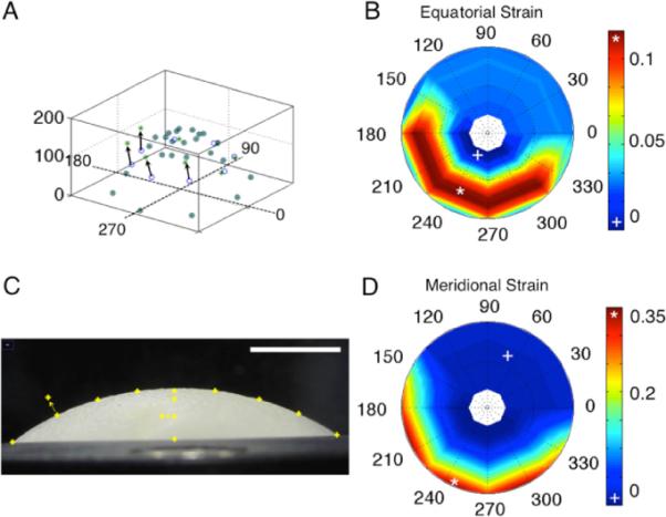
Result of moving points manually: (A) a three-dimensional reconstruction of points (vertical axis is in pixels, other axes show the rotational angle), (B) equatorial strain, (C) demonstrates how two points were moved. This image is rotated computationally about the optical axis four times to capture three-dimensional points and (D) meridional strain.
Fig. 8.

Result of testing a single piece of latex glove: (A) top-down view of the markers (units are the angle of rotation), (B) equatorial strain, (C) isometric view of the points (units in pixels), and (D) meridional strain
To confirm whether postprocessing yielded the proper results, the points were reconstructed in SolidWorks to a surface. Spline length between markers was measured in SolidWorks and Green's strain calculated. The calculated strain from the direct measurements resulted in matching values to 0.40%±0.13% of the total strain over all regions.
2.4 Scleral Testing Using the Ocugimbal
All experimental procedures for porcine eye testing were performed according to the approved protocols of the University of Arizona Institutional Animal Care and Use Committee. Porcine eyes were obtained from the University of Arizona Meat Sciences Laboratory 1 h post mortem. Immediately, the globe was cleaned of extraneous tissue (e.g., fat, muscle, etc.) and was cut in half along the equator of the eye, separating the posterior region from the anterior region. The vitreous, retina, and choroid were gently removed by pulling on the various components and wiping with cotton swaps. The optic nerve, external loose connective and fatty tissues were removed carefully to ensure the tracked markers are placed on the scleral surface. The optic nerve was cut to allow microscopic imaging of the LC. The cleaned posterior pole was mounted as described earlier and shown in Fig. 3. Removal of loose components after dissection is required to prevent obstructing the pressurization and relief lines. After placement in the Ocugimbal, filling the testing bath to cover the entire sclera, and warming the bath to 37 °C, the markers were placed on the system, and air flushed out of the system with phosphate buffered saline (PBS) (pH 7.4). The center of the LC was placed at the apex of the posterior pole, such that equatorial rotations occur about the LC, and several pictures taken at different rotations at 5 mm Hg and 30 mm Hg.
After macroscopic characterization, the Ocugimbal was placed under the microscope objective to determine microstructural organization. A baseline image was taken (λex=780 nm) after locating the center of the LC. The spherical coordinate motion control of the Ocugimbal was used to image numerous fields of view (each was 400×400 μm) over the entire LC (~2 mm wide). A small amount of overlap was captured between the images so a mosaic of the images could be created. This was done with the NIH ImageJ plugin MosaicJ (École Polytechnique Fédérale de Lausanne, Switzerland). After acquiring images at 5 mm Hg, the same Ocugimbal movement sequence was performed at 30 mm Hg while acquiring images. After LC imaging, the Ocugimbal moved to an area of the PS to acquire a single image to determine if alterations in microstructure are observed with increasing IOP. All images are shown as maximum intensity z-projections.
3 Results
Macroscopically, it was expected that nonhomogenous regions of strain would exist in the sclera. In the case of the tested porcine eye, maximum principal strain was seen in the nasal-superior regions of the sclera and was 0.105. The minimal areas of the first principal strain were observed in the nasal-inferior region and were 0.004. The equatorial strains and the meridional strains had the same magnitude in the peripapillary and peripheral sclera. The strains were higher in the region immediately adjacent to the ONH. This is shown in the contour plots in Fig. 9.
Fig. 9.
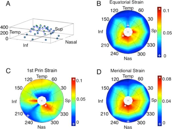
Macroscopic strain results of a porcine scleral shell from 5 to 30 mm Hg. (A) 3D view of displacement field (vertical axis is in pixels), (B) equatorial strain, (C) first principal strain, and (D) meridional strain.
The overall mosaic of the SHG signal of the LC can be seen in Fig. 10. It was expected that the majority of noticeable deformation in the microstructure would occur in the LC; however, it was unexpected that individual pore deformation would occur anisotropically. It was originally hypothesized that the pore would overall get bigger in size under pressure. Qualitatively, it was noticed that in many of the pores, they exhibited shrinking in one dimension with elongation in the other direction. Quantitatively, void ratio over the entire image region increased from 0.48 to 0.54 from 5 mm Hg to 30 mm Hg. The aspect ratio of a pore was taken to be the longest dimension divided by the shortest dimension. The average aspect ratio of 15 pores at 5 mm Hg was 1.63±0.28 and 2.46±0.42 at 30 mm Hg, indicating an elongation primarily in one direction even though tension was applied in all directions in-plane due to pressurization. Figure 11 shows the DIC result; note how fiber straining is nonhomogenous at places in the LC, with some individual regions straining as high as 0.20. The SHG and 2PEF of the PS showed little to no changes when increased to 30 mm Hg (a temporal region can be seen in Fig. 12).
Fig. 10.
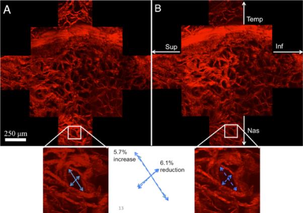
Multiphoton (SHG) image of the LC (13 multiphoton imaging regions). (A) LC at 5 mm Hg, (B) LC at 30 mm Hg. The bottom insets show a specific pore and how it changes in aspect ratio.
Fig. 11.

Digital image correlation analysis (DIC): (A) section of the LC at 5 mm Hg with blue markers from the DIC program, (B) the same region at 30 mm Hg, but without markers, and (C) the first principal strain as quantified from DIC
Fig. 12.
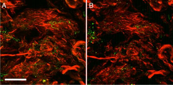
A region of the temporal PS (meridional angle 5=deg) at 5 mm Hg (A) and 30 mm Hg (B). Red in this image is SHG (collagen) while green is elastin (2PEF). Scale bar is 100 μm.
4 Discussion
This manuscript describes a device capable of characterizing the macroscopic and microscopic behavior of posterior ocular tissues. With limited imaging fields of view available during multiphoton microscopy, the implementation of a gimbal-based motion control system allows mapping of the entire LC and PS at any IOP. The gimbal-based motion control is also used to quantify the macroscopic heterogeneous strain using a cost-efficient and statically mounted standard digital camera. In addition to heterogeneous strains over large surface areas of the posterior globe, the device can provide underlying ECM deformations using nonlinear optical microscopy that can be quantified using DIC.
The representative porcine sclera tested here showed an elevated strain concentration in the nasal-superior peripapillary scleral region under the controlled elevation of IOP. Previous groups have performed pressurization experiments to examine the biomechanical response of ocular tissues. Several experiments have taken place to determine outflow facility measurements using a cannulation scheme, for instance see [16,20]. In addition, Boyce et al. ran experiments on isolated anterior ocular tissues in a pressure-inflation setup combined with stereo imaging to determine local regions of corneal strain [21]. In 2008, Girard et al. demonstrated their pressurization device, which moves a microscope head to obtain 2D strain mapping of peripapillary sclera. However, due to the limitation of their 2D measurements, there was no result regarding 3D deformation of the sclera hemisphere [9]. More recently, the 3D mapping of monkey posterior scleral shells was quantified using speckle interferometry [10]. This was used to get 3D displacements and correspondingly, finite element models were utilized to match the displacements to the biomechanical properties of the eyes. The strains seen in that study showed localized strains around the ONH as was seen in our study, with additional localization in the superior-nasal and temporal-inferior regions. In our study, we saw the same behavior, however, our porcine scleral shells exhibited higher strains on the order of roughly ten times higher than the monkey shells. The utilization of the Ocugimbal allows for a more cost-effective manner of scleral displacement through the use of a rotation scheme coupled with a standard high megapixel camera as opposed to costly laser speckle interferometry equipment.
Myers et al. performed testing of murine scleral samples with data reports of variations with age [22]. This occurred through a similar testing device: profile images of the sclera at different pressures. Digital image correlation was used to track the edges of the sclera. This presents an advantage since markers do not need to be placed on the surface. However, their method as reported does not allow quantification of the heterogeneous (regionally dependent) mechanical properties of the sclera.
There have been a few researchers that have utilized nonlinear optical microscopy to determine the microstructural organization of the optic nerve head. Most of these, however, use an approach requiring these tissues be fixed—precluding simultaneous mapping of the same specimen at increasing IOP. Some, however, have reported on methods to perform hydrated tissue microscopy, but without coupled macroscopic characterization [22–25]. These studies have shown that the microstructural organization of the LC is homogeneous, confirming that investigation of the entire LC will be necessary and useful in assessing the material properties of this tissue. For example, Winkler et al. performed multi-photon microscopy on a full, fixed, LC to look at collagen density and distribution. This study provided thorough reconstruction, however, did not look at how the microstructure changed based on location in the LC [23].
Alterations in LC microstructure have been reported before with alterations in pore size under pressure being used as a metric for identification of changes in the LC [24,25]. Previous studies reported similar behavior that we saw in relation to overall pore size increases. The pore size changes in these studies agreed qualitatively with our results in that some pores were shown to actually get smaller, while others increased in size. In our study, we reported on aspect ratio and microscopy DIC to provide a secondary metric. In addition, the utilization of the gimbal-based method allows outside areas (e.g., peripapillary sclera) to be imaged while keeping the mulitphoton imaging plane tangent to the scleral surface [24,25].
While the device described in this manuscript is being used to quantify the microstructural and macroscopic behavior of posterior ocular tissues, there are several limitations. Multiphoton microscopy is limited in terms of the depth of scanning. While the behavior of the porous LC is captured well, depths beyond 150 μm into the PS are not currently achievable. Our laboratory, however, has utilized a small angle light scattering technique to quantify the preferred fiber angle of ECM through the depth of scleral tissue in human donor tissues [26]. Another limitation of our device is that, since the eyes are cut in hemispheres as opposed to cannulated, the regions of interest for macroscopic and microstructural characterization are geometrically limited, especially at high meridional angle. Finally, our imaging of the LC, as presented here, requires the optic nerve to be severed just posterior to the LC. When imaging glaucomatous samples, then, the posterior displacement of the LC in POAG may require great care in isolating the posterior surface of the LC. Noninvasive measurements of LC cupping, for example, using SD-OCT, can be in those cases be used as a guide when severing the optic nerve. Our laboratory is also currently modifying the present device for anterior LC imaging at increasing IOPs.
Quantifying alterations of microstructure and how they relate to the macroscopic behavior can provide a link to how optic nerve head damage can be related to the overall biomechanical behavior. The device described in this manuscript has unique capabilities not only to determine how scleral shells respond to mechanical pressure, but to determine, locally, how the ECM responds to these prescribed loads. Further testing within our laboratory is ongoing to identify differences in posterior ocular tissue macroscopic and microscopic biomechanical response between healthy and glaucomatous human eyes as well as between eyes from donors of different race, sex, and age. Such research may aid in identifying how biomechanical effects may play a role in the predisposition of glaucomatous damage in high-risk populations.
5 Conclusion
We have demonstrated in this manuscript a novel device to determine the heterogeneous biomechanical macroscopic and microscopic behavior of spherical-shaped scleral specimens. This technique is unique in that samples are not fixed, frozen, or sectioned, thus allowing for assessment using nonlinear optical microscopy. This device will be an important tool for future research aimed at identifying structure-function relationships in posterior ocular tissues.
Acknowledgment
Acknowledgement is made to the donors of NGR, a program of the American Health Assistance Foundation, for support of this research (Grant No. AHAF G2009035 to JPVG). The microscope was funded by NIH/NCRR 1S10RR023737-01. This work was also partially funded by Achievement Rewards for College Scientists, Science Foundation Arizona and an NIH Cardiovascular Biomedical Engineering Training Grant (Grant No. T32 HL007955). Partial support for this work was also provided by the NIH (Grant No. NEI 1R01EY020890 to JPVG).
References
- [1].Quigley HA, Broman AT. The Number of People With Glaucoma worldwide in 2010 and 2020. Br. J. Ophthamol. 2006;90(3):262–267. doi: 10.1136/bjo.2005.081224. [DOI] [PMC free article] [PubMed] [Google Scholar]
- [2].Burgoyne CF, Morrison JC. The Anatomy and Pathophysiology of the Optic Nerve Head in Glaucoma. J. Glaucoma. 2001;10(5 Suppl 1):S16–18. doi: 10.1097/00061198-200110001-00007. [DOI] [PubMed] [Google Scholar]
- [3].Burgoyne CF, Downs JC, Bellezza AJ, Suh JK, Hart RT. The Optic Nerve Head as a Biomechanical Structure: A New Paradigm for Understanding the Role of IOP-Related Stress and Strain in the Pathophysiology of Glaucomatous Optic Nerve Head Damage. Prog. Retin. Eye Res. 2005;24(1):39–73. doi: 10.1016/j.preteyeres.2004.06.001. [DOI] [PubMed] [Google Scholar]
- [4].Ethier CR, Johnson M, Ruberti J. Ocular Biomechanics and Biotransport. Annu. Rev. Biomed. Eng. 2004;6:249–273. doi: 10.1146/annurev.bioeng.6.040803.140055. [DOI] [PubMed] [Google Scholar]
- [5].Quigley HA, Addicks EM, Green WR, Maumenee AE. Optic Nerve Damage in Human Glaucoma. II. The Site of Injury and Susceptibility to Damage. Arch. Ophthalmol. (Chicago) 1981;99(4):635–649. doi: 10.1001/archopht.1981.03930010635009. [DOI] [PubMed] [Google Scholar]
- [6].Battaglioli JL, Kamm RD. Measurements of the Compressive Properties of Scleral Tissue. Invest. Ophthalmol. Visual Sci. 1984;25(1):59–65. [PubMed] [Google Scholar]
- [7].Downs JC, Suh JK, Thomas KA, Bellezza AJ, Hart RT, Burgoyne CF. Viscoelastic Material Properties of the Peripapillary Sclera in Normal and Early-Glaucoma Monkey Eyes. Invest. Ophthalmol. Visual Sci. 2005;46(2):540–546. doi: 10.1167/iovs.04-0114. [DOI] [PubMed] [Google Scholar]
- [8].Girard MJ, Downs JC, Bottlang M, Burgoyne CF, Suh JK. Peripapillary and Posterior Scleral Mechanics—Part II: Experimental and Inverse Finite Element Characterization. ASME J. Biomech. Eng. 2009;131(5):051012. doi: 10.1115/1.3113683. [DOI] [PMC free article] [PubMed] [Google Scholar]
- [9].Girard MJ, Downs JC, Burgoyne CF, Suh JK. Experimental Surface Strain Mapping of Porcine Peripapillary Sclera Due to Elevations of Intraocular Pressure. ASME J. Biomech. Eng. 2008;130(4):041017. doi: 10.1115/1.2948416. [DOI] [PMC free article] [PubMed] [Google Scholar]
- [10].Girard MJ, Suh JK, Bottlang M, Burgoyne CF, Downs JC. Scleral Biomechanics in the Aging Monkey Eye. Invest. Ophthalmol. Visual Sci. 2009;50(11):5226–5237. doi: 10.1167/iovs.08-3363. [DOI] [PMC free article] [PubMed] [Google Scholar]
- [11].Mortazavi AM, Simon BR, Stamer WD, Vande Geest JP. Drained Secant Modulus for Human and Porcine Peripapillary Sclera Using Unconfined Compression Testing. Exp. Eye Res. 2009;89(6):892–897. doi: 10.1016/j.exer.2009.07.011. [DOI] [PubMed] [Google Scholar]
- [12].Bellezza AJ, Hart RT, Burgoyne CF. The Optic Nerve Head as a Biomechanical Structure: Initial Finite Element Modeling. Invest. Ophthalmol. Visual Sci. 2000;41(10):2991–3000. [PubMed] [Google Scholar]
- [13].Norman RE, Flanagan JG, Sigal IA, Rausch SM, Tertinegg I, Ethier CR. Finite Element Modeling of the Human Sclera: Influence on Optic Nerve Head Biomechanics and Connections With Glaucoma. Exp. Eye Res. 2011;93:4–12. doi: 10.1016/j.exer.2010.09.014. [DOI] [PubMed] [Google Scholar]
- [14].Edwards ME, Good TA. Use of a Mathematical Model to Estimate Stress and Strain During Elevated Pressure Induced Lamina Cribrosa Deformation. Curr. Eye Res. 2001;23(3):215–225. doi: 10.1076/ceyr.23.3.215.5460. [DOI] [PubMed] [Google Scholar]
- [15].Johnson DH. Human Trabecular Meshwork Cell Survival is Dependent on Perfusion Rate. Invest. Ophthalmol. Visual Sci. 1996;37(6):1204–1208. [PubMed] [Google Scholar]
- [16].Ramos RF, Stamer WD. Effects of Cyclic Intraocular Pressure on Conventional Outflow Facility. Invest. Ophthalmol. Visual Sci. 2008;49(1):275–281. doi: 10.1167/iovs.07-0863. [DOI] [PMC free article] [PubMed] [Google Scholar]
- [17].Amabili M. Nonlinear Vibrations and Stability of Shells and Plates. Cambridge University Press; Cambridge: 2008. [Google Scholar]
- [18].Eberl C, Thompson DSG, R. matlab Central. In File ID: 12413. 2006. [Google Scholar]
- [19].Keyes JT, Borowicz SM, Rader JH, Utzinger U, Azhar M, Vande Geest JP. Design and Demonstration of a Microbiaxial Optomechanical Device for Multiscale Characterization of Soft Biological Tissues With Two-Photon Microscopy. Microsc. Microanal. 17(2):167–175. doi: 10.1017/S1431927610094341. [DOI] [PMC free article] [PubMed] [Google Scholar]
- [20].Lei Y, Overby DR, Boussommier-Calleja A, Stamer WD, Ethier CR. Outflow Physiology of the Mouse Eye: Pressure Dependence and Washout. Invest. Ophthalmol. Visual Sci. 52(3):1865–1871. doi: 10.1167/iovs.10-6019. [DOI] [PMC free article] [PubMed] [Google Scholar]
- [21].Boyce BL, Grazier JM, Jones RE, Nguyen TD. Full-Field Deformation of Bovine Cornea Under Constrained Inflation Conditions. Bio-materials. 2008;29(28):3896–3904. doi: 10.1016/j.biomaterials.2008.06.011. [DOI] [PubMed] [Google Scholar]
- [22].Myers KM, Cone FE, Quigley HA, Gelman S, Pease ME, Nguyen TD. The In Vitro Inflation Response of Mouse Sclera. Exp. Eye Res. 91(6):866–875. doi: 10.1016/j.exer.2010.09.009. [DOI] [PMC free article] [PubMed] [Google Scholar]
- [23].Winkler M, Jester B, Nien-Shy C, Massei S, Minckler DS, Jester JV, Brown DJ. High Resolution Three-Dimensional Reconstruction of the Collagenous Matrix of the Human Optic Nerve Head. Brain Res. Bull. 81(2–3):339–348. doi: 10.1016/j.brainresbull.2009.06.001. [DOI] [PMC free article] [PubMed] [Google Scholar]
- [24].Agopov M, Lomb L, La Schiazza O, Bille JF. Second Harmonic Generation Imaging of the Pig Lamina Cribrosa Using a Scanning Laser Ophthalmoscope-Based Microscope. Lasers Med. Sci. 2009;24(5):787–792. doi: 10.1007/s10103-008-0641-4. [DOI] [PubMed] [Google Scholar]
- [25].Brown DJ, Morishige N, Neekhra A, Minckler DS, Jester JV. Application of Second Harmonic Imaging Microscopy to Assess Structural Changes in Optic Nerve Head Structure Ex Vivo. J. Biomed. Opt. 2007;12(2):024029. doi: 10.1117/1.2717540. [DOI] [PubMed] [Google Scholar]
- [26].Yan D, McPheeters S, Johnson G, Utzinger U, Vande Geest JP. Microstructural Differences in the Human Posterior Sclera as a Function of Age and Race. Invest. Ophthalmol. Visual Sci. 52(2):821–829. doi: 10.1167/iovs.09-4651. [DOI] [PMC free article] [PubMed] [Google Scholar]


