Abstract
Structures for Lossless Ion Manipulation (SLIM) represent a novel class of ion optical devices based upon electrodes patterned on planar surfaces, and relying on a combined action of radiofrequency and DC electric fields and specific buffer gas density conditions. Initial experimental studies have demonstrated the feasibility of the SLIM concept. This report offers an in-depth consideration of key ion dynamics properties in such devices based upon ion optics theory and computational modeling. The SLIM devices investigated are formed by two surfaces, each having an array of radiofrequency (RF) “rung” electrodes, bordered by DC “guard” electrodes. Ion motion is confined by the RF effective potential in the direction orthogonal to the boards and limited or controlled in the transversal direction by the guard DC potentials. Ions can be efficiently trapped and stored in SLIM devices where the confinement of ions can be “soft” in regard to the extent of collisional activation, similarly to RF-only multipole ion guides and traps. The segmentation of the RF rung electrodes and guards along the axis makes it possible to apply static or transient electric field profiles to stimulate ion transfer within a SLIM. In the case of a linear DC gradient applied to RF rungs and guards, a virtually uniform electric field can be created along the axis of the device, enabling ion mobility separations.
Mass spectrometry (MS) continues its rapid growth as a key technique for analyzing complex chemical and biochemical samples with an increasing array of applications.1,2 Combining MS with separation techniques, e.g. liquid chromatography or ion mobility spectrometry (IMS), enables analysis of more complex samples. Different combinations can present challenges, due to differences in sample flow rate characteristics, carrier media and/or gas pressure conditions, etc., which often results in throughput and/or sensitivity compromises. We are developing new approaches based upon Structures for Lossless Ion Manipulation (SLIM) that aim at enabling much more complex sequences of ion manipulations in one platform, with potential advantages that include greater speed and reduced sample size requirements. SLIM constitutes a novel class of ion optical devices, relying critically on a combined action of radiofrequency and DC electric fields and specific buffer gas density conditions. The lossless operation, that is, an ability to transmit and store ions with negligible losses, is one of the key attributes of the SLIM concept. The property is inherited, e.g., from the ion funnel and ion funnel trap devices, for which it has been demonstrated both theoretically and in a number of experimental studies.3–6 Early experimental evidence for the lossless operation included the observation of ion current transmitted though the ion funnel without noticeable losses.4,5 Such highly efficient transmission is observed over a wide m/z range and can be maintained using a range of RF voltages and frequencies, in line with the theoretically predicted lossless regime character- istics.3,5 From the ion dynamics perspective, the lossless regime is realized when the potential well exceeds the ion kinetic energy. In the 1 Torr pressure range ions are efficiently thermalized and the potential well sufficient for the lossless operation needs to be significantly higher than the thermal energy, which can be achieved using appropriately chosen electrode configurations.
The SLIM concept introduces the use of DC elements to confine ions, in addition to the assembly of RF electrodes generating the pseudopotential well, as used previously in the ion funnel and related devices, and can greatly increase the versatility of potential devices based upon the approach. In contrast to conventional constant field drift tube7–9 and traveling wave10,11 devices, SLIM devices can potentially be readily assembled into many alternative arrangements. Here, we demonstrate this ability by evaluating a basic building block needed to enable complex manipulations, a linear SLIM component, comprising RF/DC guiding electrodes and DC guard electrodes. Using printed circuit board (PCB) based SLIM devices allows for a multitude of electrode designs to be rapidly fabricated, tested, and applied at low cost based on the results of ion trajectory and potential calculations. The SLIM devices are not fundamentally limited to IMS experiments and can be configured for various pressure environments. We aim to utilize these devices in the future to allow for extended series of ion manipulations of biologically relevant macromolecules and complex mixtures currently unattainable by state-of-the-art instrumentation.
Initial experimental studies have demonstrated the feasibility of the SLIM concept.12 This report offers an in-depth consideration of the ion dynamics properties of the devices, based on ion optics theory and computer modeling. Ion dynamics theory is applied to analyze the ion motion driven by radiofrequency (RF) and DC electric fields, in a bath gas environment. We begin with analysis of the potential wells generated by SLIM electrodes, considering how various proportions of the device influence the ion focusing properties. Ions transmitted in the SLIM device experience combined action of DC electric fields and intense RF fields, which can provide conditions for collisional activation, as we consider next. Further, we explore the ion capacity of a linear section of the SLIM. Finally, we analyze the potential performance of the SLIM configured as an ion mobility spectrometer (IMS).
METHODS
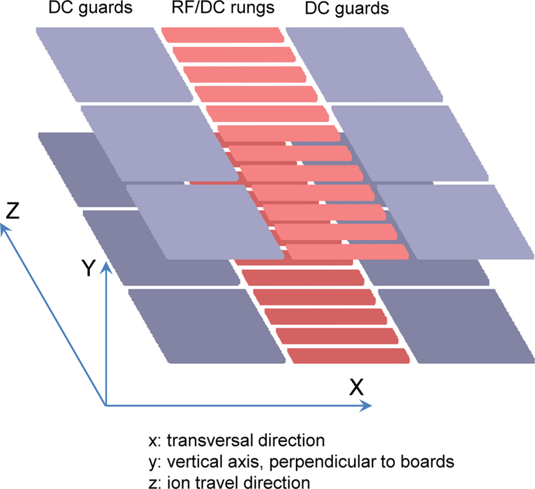
The modeling and theoretical approach was originally developed for the simulation driven development and optimization of the ion funnel.3,5 The SLIM devices considered in this study are formed by two planar and parallel boards, each having a sequence or RF “rung” electrodes, bordered by DC “guard” electrodes (Figure 1). Ion motion is confined by the RFeffective potential13,14 in the direction orthogonal to the boards and is limited by the guard DC potentials in transverse directions. Figure 1 illustrates the coordinate system used in the context of a short SLIM section. The RF voltages are applied to the rungs with alternating phase on adjacent electrodes. In addition to the RF voltages, the rungs can carry a DC gradient that can direct ion motion along the Z-axis. Such an arrangement is often implemented in ion funnels and related devices.3–6 The DC-only guard electrodes limit ion motion in the transversal dimension (i.e., X-axis).
Figure 1.
Section of the Structure for Lossless Ion Manipulation, formed by two planar boards, each having DC guard electrodes and central RF/DC rung electrodes; the coordinate system as used for modeling modeling is shown on the left.
Thus, ion motion in the SLIM device is driven by a combination of forces produced by the sum of the DC electric field EDC and the effective potential field Eeff:
Here z is the charge state of the ion, and e is the elementary charge; the total force F, as well as EDC and Eeff, are 3D vector functions of coordinates X, Y, and Z. The effective potential field Eeff is calculated as a gradient of the effective potential Veff, which in turn is a scalar function of coordinates, defined by the local intensity of the RF electric field ERF:13,14
The ion mass m is expressed in SI units; the angular frequency ω is related to the RF frequency f (Hz) as ω = 2πf. The DC and RF potential distributions can be obtained by solving the Laplace equation, using the DC and RF potentials applied to boundaries shaped as the SLIM electrodes. There is no exact analytical expressions for such geometries; thus, we rely on numerical solutions. The potential calculations reported here are based on a custom developed approach that provides direct potential calculations for complex 3D geometries.15–17
RESULTS
Effective Potentials in SLIM
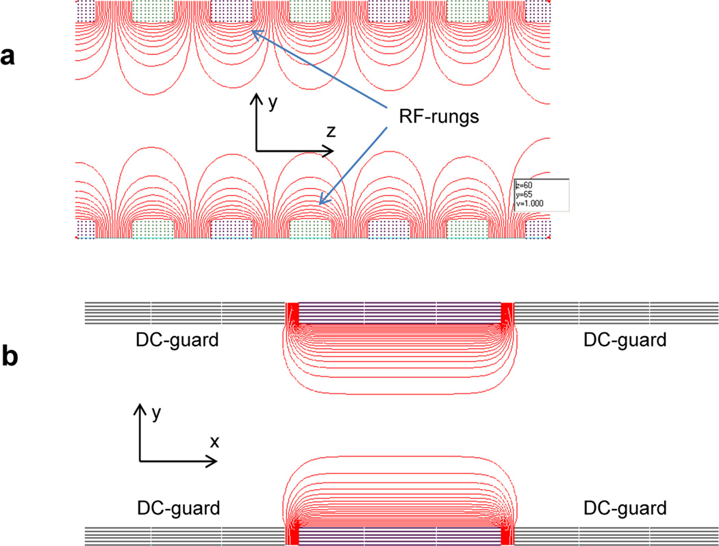
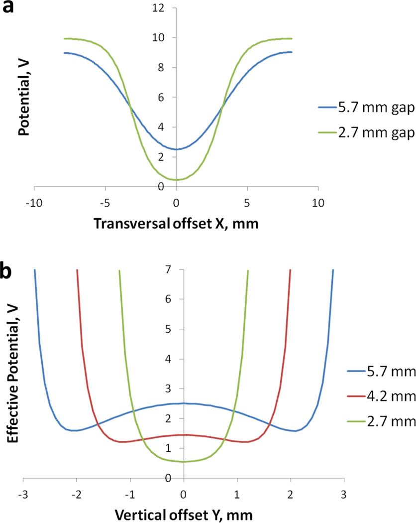
The RF field distribution between the two surfaces forming the SLIM device is depicted in Figure 2. Equipotential contours in the top portion of Figure 2a show intense electric fields in areas close to rungs; at the plane of symmetry in the center the field intensity is reduced forming a nearly field-free region. The transversal cross section (Figure 2b) shows flat equipotential contours in the center region and negligible field intensity extending beyond the central rungs between guard electrodes. Such a distribution produces steep effective potential wells along RF rung electrodes and a nearly flat potential at midplane. There is no confinement in the X-direction, as opposed to the ion funnel, where circular RF electrodes surround the area of ion drift. In the border between the RF rungs and the guard electrodes, a repulsive force is created which drives ions outward. Opposing this repulsion force is the DC electric field, defined by the DC offset between the guard electrodes and RF rungs. The DC potential can be applied to the guards to constrain ion motion in the X dimension and confine ions in the central region between the arrays of rung electrodes on the opposing surfaces. Two example geometries are considered in Figure 3a, showing the guard DC potential as a function of X. In each case RF/DC rungs are 5.3 mm long and 0.76 mm wide, with separation of 0.76 mm and a DC offset of 10 V applied to the guards. A wider gap between the boards (5.7 mm) leads to an increased penetration of the DC potential to the center, ~2.5 V at the minimum. In the case of a narrow gap (2.7 mm), the central DC potential is reduced to ~0.45 V. The smaller penetration for the narrower gap results in weaker ion focusing in the transversal directions, i.e., a wider area around the center that can be occupied by ions.
Figure 2.
Equipotential contours for the RF fields from potentials applied to the central rung electrodes: (a) cross section along the YZ plane of symmetry; (b) transversal cross section, XY plane.
Figure 3.
(a) DC potential profiles for rungs 5.3 mm wide, for either 2.7 mm or 5.7 mm spacing between the SLIM surfaces. The wider gap (5.7 mm) provides tighter focusing in the transverse (X) dimension due to greater penetration of fields from the guard electrodes; (b) SLIM effective potential in the vertical (Y) dimension, at the midplane X = 0, for different interboard spacings. A local maximum in the center between boards, Y = 0, is increased for wider spacing, 5.7 mm (blue) due to increased field penetration from the DC guards. The local maximum is reduced for 4.2 mm spacing (red) and disappears for the smaller 2.7 mm spacing (green).
Ion density distributions for the SLIM designs considered here will result from the combined action of the DC field from the guard electrodes and the effective RF focusing generated by the rungs. Figure 3b shows profiles for the combined potential, Veff + VDC, as a function of the vertical coordinate (Y). The effective potential Veff was calculated for RF rungs configured as described above, f = 0.8 MHz, RF voltage 100Vp-p, m/z 1000. The DC potential at the central plane YZ shows a local maximum at the center that is reduced near the surfaces due to increased screening of the external DC field by the rungs. The combined potential can have the local maximum in the center Y = 0), when the guard DC potential is high enough, so that the local VDC(Y) maximum prevails over the central minimum of the effective potential Veff(Y). A pronounced local maximum is seen in the case of wider gap, 5.7 mm; the “hump” is reduced for 4.2 mm gap and completely removed in the case of narrow gap, 2.7 mm. The configurations in Figure 3b were calculated for rungs 5.3 mm long; when using a wider SLIM configuration having 8.4 mm long rungs, the local maximum was not created for a 4.2 mm gap. However, such a configuration compromises ion focusing in the X direction due to a combination of wider rungs and poor penetration of the guard DC field.
A smaller gap, < ~4 mm, has the advantage of a more robust operation with respect to imperfections of the guard potentials, such as created when the guard length covers a number of rungs. Larger gaps, up to 6 mm, require a more precise adjustment of the guard potential, possibly using shorter guards covering fewer rungs, but also have the advantage of better focusing in the direction orthogonal to the ion path. However, the increased penetration of the guard DC field also serves to increase the extent of ion collisional excitation, as discussed next. Based on such considerations, we selected an interboard gap of approximately 5 mm in conjunction with designs having 5.3 × 0.76 mm rungs and 0.76 inter-rung spacing as among those for more detailed theoretical end experimental evaluation.
Collisional Activation of Ions in the SLIM Designs Studied
One initial SLIM implementation has used a spacing of 4.76 mm between surfaces (to be described in detail elsewhere12), which is in line with the optimal gap dimensions for devices with the electrode dimensions discussed above. Ions confined between the surfaces will tend to be localized in two potential wells ~1 mm above and below the midplane (Figure 3b) and separated by a barrier of 0.24 V. While small, the barrier is sufficient in the absence of significant space charge to divide ions into two distinct packets, since the ion density distribution along the vertical (Y) axis is governed by the Boltzmann distribution with the thermal energy (0.025 eV) in the denominator of the exponent.18,19 This configuration differs from the one encountered in collisional focusing multipoles, with ions occupying an area along the axis of symmetry and where the RF field intensity vanishes.19 In the current configuration, the DC electric field shifts the ion equilibrium position into a region of nonzero RF field intensity, where some limited collisional activation can occur. The degree of the RF ion heating can be evaluated in terms of the effective temperature:20
The ion temperature is increased above the gas temperature by ΔTeff = 21 K, corresponding to only minor collisional activation. The calculation used mg = 28 for the N2 gas molecular mass, the ion mass and charge m = 1000, z = 1, and the effective potential at the local minimum Veff = 0.1 V. While further optimization of the gap and electrode dimensions can undoubtedly further reduce such effects, we also conclude that the ion confinement by means of the combination of the DC electric field and the RF effective field in the present SLIM configuration provides a viable alternative to RF-only devices, such as RF multipoles.
Ion Charge Capacity for the SLIM Design Studied
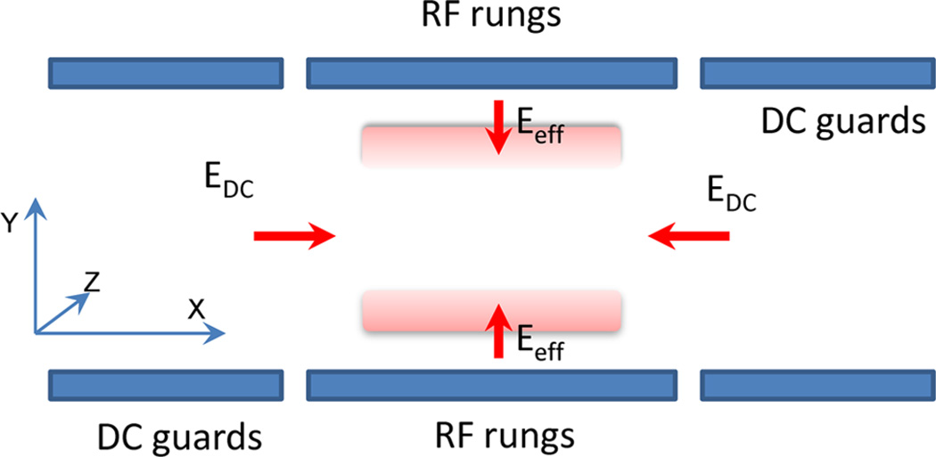
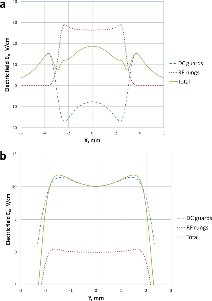
The ion charge capacity for SLIM can be estimated based on the opposing forces of Coulombic repulsion and that due to the DC electric field and effective RF field generated from the potential applied to the SLIM electrodes. Figure 4 shows electric fields balancing the Coulomb repulsion of the stored ion charge. The electric field produced by the stored ions is balanced by the DC electric field from guard electrodes, EDC, plus the field Eeff due to the effective potential generated by RF electrodes, with the ion population split into two strips, aligned as noted above. The effective field orthogonal to the electrodes confines Coulombic driven expansion in the Y-direction. The field produced by DC guards contributes to the vertical (Y) component with the opposite sign, slightly reducing the RF effective focusing. Figure 5a shows transversal (X) profiles of the vertical (Y) components of the DC electric field and the RF effective field, calculated based on 3D potential modeling, using parameters of the trapping experiment:21 RF frequency 2.4 MHz, RF voltage 165 Vpp, ions m/z 466.3, singly charged, and the DC guard offset 6.6 V. The total confining field (solid curve, Figure 5a) reaches 18.7 V/cm in the center (X = 0), and decreases to 12.5 V/cm approaching the sides of the RF rungs at X = ±2 mm. The Ey profiles in Figure 5a were calculated for a vertical position Y = 1.8 mm from the midplane, corresponding to efficient confinement from the sides. Figure 5b shows vertical (Y) profiles of the horizontal fields Ex, confining the stored ion charge from the sides, plotted for the vertical XZ plane at X = 2 mm, bordering the range of Y-confinement in Figure 5a. The total of two x-fields (solid curve in Figure 5b) reaches a maximum of 11.8 V/cm at y = ±1.5 mm and declines steeply for vertical offsets above 2 mm. The decline of X-confinement at high vertical positions is due to two factors: the DC field screened by the rungs and the RF effective field acting to eject ions from the area of high effective potential close to RF rungs. As a result, the vertical expansion of the ion cloud is effectively limited at Y < ≈2 mm; further expansion leads to leakage of ions through the reduced x-barriers at the sides. Accordingly, the total stored ion charge Q can be estimated based on the confining field intensity, using Gauss’s relationship:
Figure 4.
Storage of ions in the SLIM section. The Coulomb repulsion forces are balanced by the DC electric field produced by guard electrodes and the RF effective focusing field from RF rung electrodes.
Figure 5.
Electric field confining stored ion charge (a) in the vertical dimension, Y-components, and (b) in the horizontal dimension, X-components. The DC electric field produced by the guard electrodes (dashed), effective potential field from RF rung electrodes (dotted), and a sum of the two fields (solid).
Here ε0 is the electric constant; the electric field flux FE is defined as an integral of the field produced by the stored charge over a closed surrounding surface.22 Considering the two- dimensional approximation, the electric field flux is estimated as
where Δx and Δz are the x and z dimensions of a rectangular area of the stored charge; the Coulomb field Ey is counter- balanced by the total field in Figure 5a. The total number of elementary charges stored in the SLIM section would be
The X-range used for the estimation is Δx = 4 mm; the length of the trapped charge region is equal to the length of the trapping SLIM section, Δz = 15.24 cm; electric field Ey =15 V/ cm corresponds to experimental conditions, as evaluated above (Figure 5a).
The estimated charge capacity agrees with that observed in initial experiments using a linear SLIM section to trap ions,21 and is among the highest stored charge amounts reported. The ion funnel trap used with IMS is capable of storing up to 107 elementary charges.23 In terms of the linear charge density, the value obtained, Qz ~ 10−10 C/m, compares favorably with the charge capacity of RF multipoles.24 The ability of the device to create the DC field gradient to stimulate a ion transport along the axis can be used to achieve significant ion currents; e.g., for the field Ez ~ 40 V/cm, the ion velocity vz ~ 100 m/s, and the ion current is i = Qz vz ~ 10 nA, corresponding to the high end of use in MS with, e.g., ESI or MALDI sources.
Potential for Ion Mobility Separations in SLIM
As discussed above, ions can be efficiently trapped and stored in SLIM devices; the confinement of ions can be “soft” with respect to collisional activation, similar to RF-only multipole ion guides and traps. An additional functionality of SLIM is provided by the segmentation of the RF rung electrodes and guards along the Z axis resulting in electric field profiles that will stimulate ion motion. We consider a basic case of a DC linear gradient applied to RF rungs and guards, such that a virtually uniform electric field Ez is created along the axis of the device. Considering the elevated pressure, > ~1 Torr nitrogen bath gas, the ion motion stimulated by the electric field represents a drift with a constant velocity, defined by the ion mobility K:25
The pressure conditions are similar to IMS-TOF MS platforms incorporating electrodynamic ion funnels23,26,27 with an ion drift region, in the form of a drift tube, where a constant and uniform electric field and a bath gas having negligible flow velocity provide conditions for the ion drift according to the above equation.7–9 In the case of a linear SLIM region having a constant axial field, the ion cloud is shaped by confining fields, the effective RF focusing in the vertical dimension, and DC electric fields generated by the guard electrodes.
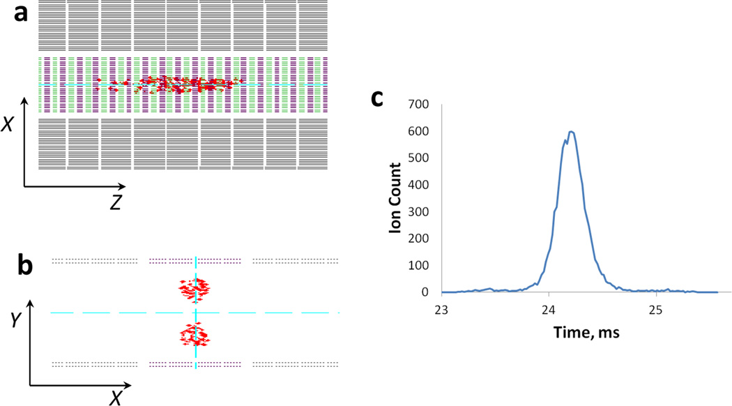
A computer model of the ion motion has been implemented to analyze details of the ion motion in such a configuration (Figure 6). Ions form into two elongated packets, each occupying a local Y-potential well (Figure 3b). The ion density distribution along the Z-axis takes the form of a Gaussian having the exponential width defined by diffusion. The vertical split is orthogonal to the ion drift and does not affect the Gaussian arrival time distribution (Figure 6c).
Figure 6.
Modeling the ion mobility separation in a straight SLIM section. Ion density distribution for a pulse of ions in a horizontal XZ projection (a), vertical XY planar projection (b), and calculated ion arrival time distribution (c).
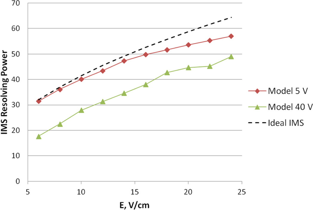
The ion drift time and IMS resolving power have been modeled for conditions of an initial experimental study12 for ions of m/z 922. The ion cross section was measured independently using the IMS TOF instrument27 and used to calculate the ion mobility for 4.1 Torr nitrogen, at 298 K, the conditions employed in our experimental study.12 The ion drift time vs electric field intensity shows a close agreement between the model and experiment.12,28 The IMS resolving power in Figure 7 has been modeled for the guard DC offset of 5 V, the same as experiment, and for an increased offset of 40 V. For the lower offset, 5 V, modeling results approach the theoretical IMS resolving power for low electric fields and trend lower for higher fields. Modeling results for the increased guard offset of 40 V show a resolving power profile noticeably lower than the theoretical one across the range of electric fields. This can be explained considering the axial variations of the effective potential, which contribute to the temporal dispersion of ions, when the increased DC field drives ions closer to RF electrodes. We conclude that the RF field and irregularities of the DC gradient do not degrade the quality of IMS measurements in SLIM when reasonably optimal conditions are chosen. This is supported by the initial experimental study showing SLIM IMS resolving power closely matching theoretical calculations.12,28 We also note that mobility separations using transient DC fields (e.g., traveling waves) are similarly feasible.
Figure 7.
Ion mobility resolving power as a function of electric field intensity. Modeling results for the guard offset 5 V (diamonds), offset 40 V (triangles), and calculated assuming the ideal IMS drift tube (dashed).
CONCLUSIONS
The ion confinement in SLIM is accomplished by a combination of the effective potential generated by the RF rung electrodes, and DC potential offset from the guard electrodes. The relative sizes of the electrodes, applied voltages, and surface spacing have been initially optimized for ion confinement conditions. Potential calculations have been applied to analyze the RF and DC potential profiles for various SLIM geometries. Configurations having rung electrode lengths significantly shorter than the separation between boards display a significant penetration of the guard DC potential into the central volume. This creates conditions for ion packets such that they can be split into two volumes. Alternatively, geometries with smaller interboard gaps produce a single, nonsplit ion packet extended in the transversal direction.
Ions confined in SLIM experience combined effects of the DC electric and RF fields, which create conditions for potentially sustained collisional activation. For the optimal geometry and moderate guard potentials, however, only very minor collisional ion activation is produced, with the effective ion temperature increased above the bath gas temperature by ~10 K. In this respect, SLIM devices provide a viable alternative to the RF-only multipole ion guides and traps, with negligible collisional activation of ions.
The ion capacity of a linear section of the present SLIM design is estimated to be ~108 elementary charges for a section 10 cm long, an ion population among the highest achievable in ion traps.
Computer modeling of ion motion supports the lossless ion transmission for the SLIM configurations studied. A precise modeling of the ion diffusion inside a linear drift region supports the capability for high quality ion mobility measurements using SLIM, a finding that we experimentally confirm elsewhere.12,28 Overall, the SLIM ion dynamics modeling study consistent with initial experimental observations, as well as the observation of efficient ion transmission in IMS experiments, and with the lossless ion trapping and storage extending to high ion populations, up to 108 ions, and for significantly extended times, ≫1 s.21
Supplementary Material
ACKNOWLEDGMENTS
Portions of this research were supported by grants from the National Institute of General Medical Sciences (P41 GM 103493-11), the Laboratory Directed Research and Development Program at Pacific Northwest National Laboratory, and the U.S. Department of Energy Office of Biological and Environmental Research Genome Sciences Program under the Pan-omics project. Work was performed in the W. R. Wiley Environmental Molecular Sciences Laboratory (EMSL), a DOE national scientific user facility at the Pacific Northwest National Laboratory (PNNL).
Footnotes
The authors declare no competing financial interest.
References
- 1.Chait BT. Annu. Rev. Biochem. 2011;80:239–246. doi: 10.1146/annurev-biochem-110810-095744. [DOI] [PubMed] [Google Scholar]
- 2.Angel TE, Aryal UK, Hengel SM, Baker ES, Kelly RT, Robinson EW, Smith RD. Chem. Soc. Rev. 2012;41:3912–3928. doi: 10.1039/c2cs15331a. [DOI] [PMC free article] [PubMed] [Google Scholar]
- 3.Tolmachev AV, Kim T, Udseth HR, Smith RD, Bailey TH, Futrell JH. Int. J. Mass Spectrom. 2000;203:31–47. [Google Scholar]
- 4.Kim T, Tolmachev AV, Harkewicz R, Prior DC, Anderson GA, Udseth HR, Smith RD, Bailey TH, Rakov S, Futrell JH. Anal. Chem. 2000;72:2247–2255. doi: 10.1021/ac991412x. [DOI] [PubMed] [Google Scholar]
- 5.Page JS, Tolmachev AV, Tang K, Smith RD. J. Am. Soc. Mass Spectrom. 2006;17:586–592. doi: 10.1016/j.jasms.2005.12.013. [DOI] [PMC free article] [PubMed] [Google Scholar]
- 6.Kelly RT, Tolmachev AV, Page JS, Tang K, Smith RD. Mass Spectrom. Rev. 2009:1–19. doi: 10.1002/mas.20232. [DOI] [PMC free article] [PubMed] [Google Scholar]
- 7.Bowers MT, Kemper PR, von Helden G, van Koppen PAM. Science. 1993;260:1446–1451. doi: 10.1126/science.260.5113.1446. [DOI] [PubMed] [Google Scholar]
- 8.Clemmer DE, Jarrold MF. J. Mass Spectrom. 1997;32:577–592. [Google Scholar]
- 9.Eiceman GA, Karpas Z. Ion Mobility Spectrometry. 2nd ed. Boca Raton, FL: CRC Press; 2005. [Google Scholar]
- 10.Giles K, Pringle SD, Worthington KR, Little D, Wildgoose JL, Bateman RH. Rapid Commun. Mass Spectrom. 2004;18:2401. doi: 10.1002/rcm.1641. [DOI] [PubMed] [Google Scholar]
- 11.Giles K, Williams JP, Campuzano I. Rapid Commun. Mass Spectrom. 2011;25:1559. doi: 10.1002/rcm.5013. [DOI] [PubMed] [Google Scholar]
- 12.Webb IK, Garimella S, Tolmachev AV, Zhang X, Chen T, Norheim RV, Anderson GA, Ibrahim YM, Smith RD. Anal. Chem. 2014 doi: 10.1021/ac502054p. [DOI] [PMC free article] [PubMed] [Google Scholar]
- 13.Dehmelt HG. Adv. Atom Mol. Phys. 1967;3:53–290. [Google Scholar]
- 14.Gerlich D. In: In State Selected and State-to-State Ion–Molecule Reaction Dynamics. Part 1. Experiment. Ng CY, Baer M, editors. LXXXII. New York: Wiley; 1992. pp. 1–176. [Google Scholar]
- 15.Tolmachev AV, Robinson EW, Wu S, Smith RD, PašsaTolić L. J. Am. Soc. Mass Spectrom. 2011;22:1334–1342. doi: 10.1007/s13361-011-0167-z. [DOI] [PubMed] [Google Scholar]
- 16.Tolmachev AV, Robinson EW, Wu S, Smith RD, Futrell JH, PašaTolić L. J. Am. Soc. Mass Spectrom. 2012;23:1169–1172. doi: 10.1007/s13361-012-0395-x. [DOI] [PMC free article] [PubMed] [Google Scholar]
- 17.Tolmachev AV, Robinson EW, Wu S, Smith RD, Leach FE, Futrell JH, PašaTolić L. Int. J. Mass Spectrom. 2012;325:45–50. [Google Scholar]
- 18.Tolmachev AV, Chernushevich IV, Dodonov AF, Standing KG. Nucl. Instrum. Methods B. 1997;124(1):112–119. [Google Scholar]
- 19.Tolmachev AV, Udseth HR, Smith RD. Int. J. Mass Spec. 2003;222:155–174. [Google Scholar]
- 20.Tolmachev AV, Vilkov AN, Bogdanov B, PašaTolić L, Masselon CD, Smith RD. J. Am. Soc. Mass Spectrom. 2004;15:1616–1628. doi: 10.1016/j.jasms.2004.07.014. [DOI] [PubMed] [Google Scholar]
- 21.Zhang X, Garimella S, Prost SA, Webb IK, Chen T, Tang K, Tolmachev AV, Norheim RV, LaMarche BL, Danielson WF, 3rd, Baker ES, Anderson GA, Ibrahim YM, Smith RD. An Initial Evaluation of Ion Traps in Structures for Lossless Ion Manipulation (SLIM) at a High Pressure: Ion Storage, Ion Accumulation and Ion Ejection. Anal. Chem. (in preparation) [Google Scholar]
- 22.Grant IS, Phillips WR. Electromagnetism. 2nd ed. John Wiley & Sons; 2008. Manchester Physics Series; ISBN 978-0-471-92712-9. [Google Scholar]
- 23.Tolmachev AV, Clowers BH, Belov ME, Smith RD. Anal. Chem. 2009;81:4778–4787. doi: 10.1021/ac900329x. [DOI] [PMC free article] [PubMed] [Google Scholar]
- 24.Tolmachev AV, Udseth HR, Smith RD. Anal. Chem. 2000;72:970–978. doi: 10.1021/ac990729u. [DOI] [PubMed] [Google Scholar]
- 25.Mason EA, McDaniel EW. Transport Properties of Ions in Gases. New York: Wiley; 1988. [Google Scholar]
- 26.Tang K, Shvartsburg AA, Lee HN, Prior DC, Buschbach MA, Li F, Tolmachev AV, Anderson GA, Smith RD. Anal. Chem. 2005;77:3330–3339. doi: 10.1021/ac048315a. [DOI] [PMC free article] [PubMed] [Google Scholar]
- 27.Baker ES, Clowers BH, Li F, Tang K, Tolmachev AV, Prior DC, Belov ME, Smith RD. J. Am. Soc. Mass Spectrom. 2007;18:1176–1187. doi: 10.1016/j.jasms.2007.03.031. [DOI] [PMC free article] [PubMed] [Google Scholar]
- 28.Sandilya VB, Garimella SVB, Ibrahim YM, Webb IK, Tolmachev AV, Zhang X, Anderson GA, Smith RD. Simulation of Electric Potentials and Ion Motion in Planar Electrode Structures for Lossless Ion Manipulations (SLIM) J. Am. Soc. Mass Spectrom. doi: 10.1007/s13361-014-0976-y. accepted for publication. [DOI] [PMC free article] [PubMed] [Google Scholar]
Associated Data
This section collects any data citations, data availability statements, or supplementary materials included in this article.


