

Abstract
Effects of shock waves on the morphology and cytoskeleton of a human renal carcinoma cell line (ACHN) were investigated in vitro. ACHN monolayer cultured on a cover slide glass was treated with 10 shots of focused underwater shock waves, with 16 MPa peak pressure at the focal area of a piezoceramic shock wave generator. After exposure to the shock wave, based on the severity of morphological deformations of the treated cells, the monolayer was divided into three morphological areas; focal, marginal and intact. Morphological deformations were found to be associated with disorganization of the intracellular cytoskeletal filaments. Deformation of the cytoskeletal proteins in the treated cells were separately studied with respect to the location of the cells within the three morphological areas. Among three major cytoskeletal proteins, actin and tubulin, but not vimentin, were affected by the shock waves. The deformed cells reorganized their cytoskeletal network within 3 h with a pattern similar to the control, indicating the transient characteristic of the shock wave induced cytoskeletal damage in the surviving cells. The remaining cell fragments on the slide glass, which contained short actin filaments, indicated the important role of shear stress in damaging the cytoskeletal fibers by shock waves. (Cancer Sci 2006; 97: 296–304)
Extracorporeal Shock Wave Lithotripsy (ESWL) has become a common clinical procedure for treatment of kidney stones. Shock waves have been successfully applied for the treatment of bone and tendon disorders consisting of pseudarthrosis, plantar fasciitis, calcifying tendinitis of the shoulder and radial or ulnar epicondylitis. Meanwhile, ESWL's ability to damage cells has opened up a new area of research using shock wave application for cancer therapy.( 1 , 2 ) To understand the mechanism of shock wave induced cell damage, several in vitro and in vivo investigations have been carried out to analyze the effects of shock waves on the cell ultra‐structure.( 3 , 4 , 5 ) The cell membrane was reported to be the most sensitive part of a cell to shock wave exposure.( 6 ) The cavitation phenomenon and shear stress have been reported to be the main mechanisms behind membrane damage.( 7 )
It is believed that shock wave administration induces a spectrum of effects ranging from permanently increasing cell membrane permeability when the cell dies, to transiently increasing permeability when the damaged cell will survive, a process known as poration.( 8 ) After successfully transferring large molecules and DNA into tumor cells by shock waves, the mechanism of poration generated by acoustic waves has become an interesting research topic in recent years.( 9 ) Poration has been mostly regarded as a consequence of mechanical forces, such as shear stress and the jet phenomenon, generated by acoustic waves and cavitation.
Effects of shock waves on cells have been mostly studied from a mechanical point of view, with less attention paid to the role of the cell ultra‐structure when shock waves are administered. However, it is essential to take into account the interaction of shock waves with intracellular structures, such as the cytoskeleton, as an important supporting system for the cell membrane.
Cytoskeletal proteins, especially actin filaments, have been shown to form stable contacts with the cytoplasmic face of the plasma membrane. Cytoskeleton–membrane interaction controls cellular functions such as cell motility, morphology and intracellular transportation. It also plays a crucial role in cell membrane attachment to the substratum that provides mechanical support to the plasma membrane.
In the present study, interaction of shock waves with renal tumor cells was studied with regard to their cytoskeleton as a major cellular system to resist mechanical stress.
Materials and Methods
Cell line
ACHN cells, a human renal carcinoma cell line (Dainihonseiyaku, Japan), were cultured in modified Eagle's medium (MEM) in humidified 5% CO2 at 37°C. The medium was supplemented with 10% fetal calf serum (FCS), 1% penicillin/streptomycin and 1% L‐glutamine (all from GibcoBLR, Grand Island, NY, USA). Cells were seeded on a cover slide glass at a density of 1 × 10⁴ cells/mL for 4 days to reach a subconfluent state.
Shock wave experimental arrangement
A partial spherical piezoceramic dish with a 125 mm internal diameter and 16 mm depth with a maximum peak overpressure of 16 MPa (at a voltage discharge of 1.5 kV) in its focal zone was used as the shock wave generator. The dish was placed at the bottom of a degassed water bath of 200 mm × 200 mm × 230 mm dimension at 30°C. Pressure profile of the generator was measured using a polyvinylidene fluoride (PVDF) needle hydrophone with a 0.5 mm diameter sensitive area and 50 ns rise time (Muller‐Platte‐Gauge, Ingenieurtechnik, Germany). The pressure sensor's response time was short enough to accurately capture the peak pressure value at the shock front. The measuring surface of the pressure gauge faced the incident shock wave, so that the face‐on shock pressure was recorded. By positioning the transducer at different distances from the focal point, the focal extensions were determined to be 3 mm in lateral and 13 mm in axial directions.(
10
)
Fig. 1 shows a diagram of the experimental system. A pressure history measured at the focal point of the generator at a voltage discharge of 0.1 kV is shown in Fig. 2. By increasing the driving voltage, the non‐linear effect increased to produce a single large positive shock front. In comparison with an ultrasonic wave of 0.1 kV discharge, a steep shock front was observed at 0.5 kV and higher driving voltages. Fig. 3a–b shows the measured pressure history at the focal point and the lateral peak pressure distribution of the focal area after a maximum voltage discharge of 1.5 kV. The waveform at 1.5 kV has a positive peak pressure of 16 MPa with 0.6 µs positive pulse duration, and a negative tensile pressure of 2.0 MPa with 1.8 µs duration. The pulse intensity or energy flux density is defined as the time integral of squared waveform  over the pulse duration, divided by ρc, where ρ is the density and c is the speed of sound of the fluid.(
11
) The pulse intensity at the focal point for the voltage discharges of 0.1 and 1.5 kV are 0.002 and 0.041 mJ/mm2, respectively.
over the pulse duration, divided by ρc, where ρ is the density and c is the speed of sound of the fluid.(
11
) The pulse intensity at the focal point for the voltage discharges of 0.1 and 1.5 kV are 0.002 and 0.041 mJ/mm2, respectively.
Figure 1.
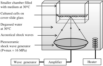
Schematic diagram of the experimental set‐up with a piezoceramic generator placed at the bottom of a degassed water bath. Cell monolayer cultured on cover slide glass positioned at the focal area of the piezoceramic dish was treated with 10 shock waves with P+ max = 16 MPa.
Figure 2.
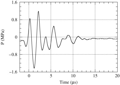
Measured pressure history at the focal point for a discharge voltage of 0.1 kV.
Figure 3.
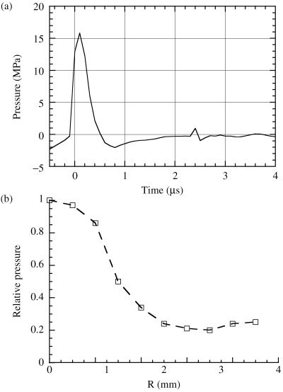
(a) Measured pressure history at the focal point; (b) the lateral peak pressure distribution of the focal area after a maximum voltage discharge of 1.5 kV.
For shock wave treatment, the cover slide glass covered with the subconfluent cell monolayer was fixed in a smaller chamber of 70 mm × 70 mm × 70 mm dimension and filled with the medium at 30°C. The chamber, whose bottom was cut and sealed with a thin polyethylene film of 25 µm thickness, was positioned in the water bath as the slide glass was at the focal area with the cell monolayer at the site of shock wave entry. A sham‐exposed monolayer was prepared in the same way except for the shock waves.
The cover slide glass had a 160 µm thickness with the following physical properties: density ρ = 2.49 g/cm3, Young's modulus E = 73.3 GPa, Poisson's ratio ν = 0.23, longitudinal sound speed cL = 5840, and shear wave speed cS = 3460 m/s.
Scanning electron microscopy
The shock wave treated monolayers were immediately fixed in 2.5% gluteraldehyde plus 2% paraformaldehyde for 2 h and then postfixed in 1% osmium‐tetroxide solution for 1 h. After dehydration in an ascending ethanol series, the monolayer was dried with liquid CO2 with a critical point dryer (Hitachi, Tokyo, Japan) and sputtered with platinum‐palladium (Pt‐Pd). Morphology of the shock wave treated monolayers was compared with a control monolayer under a SEM S‐3200 N scanning electron microscope (Hitachi).
Fluorescence microscopy
A single staining immunofluorescence method was used to stain β‐actin‐containing microfilaments, β‐tubulin in microtubules, and vimentin intermediate filaments. Fluorescein‐phalloidin (Molecular Probes, OR, USA), anti‐β‐tubulin (Biogenesis, UK) and antivimentin antibody (Dako, Tokyo, Japan) were used for immunostaining actin, tubulin and vimentin, respectively. The shock wave treated monolayers were fixed with 4% paraformaldehyde for 10 min, permeabilized with 0.1% saponin for 30 min, and incubated with the monoclonal antibodies for 1 h. All procedures were carried out at room temperature. Because the monoclonal antibodies for β‐tubulin and vimentin were not fluorescein (FITC) conjugated, those monolayers incubated with the antitubulin or antivimentin antibodies were further incubated with FITC conjugated antimouse IgG + IgM (Sigma Chemical, Tokyo, Japan) for 30 min. Cytoskeleton of the SW‐treated and sham‐treated cells were compared under an Eclipse‐E800 fluorescence microscope (Nikon, Tokyo, Japan).
To determine the ability of the shock wave treated cells to reassemble their fibrillar structures, the detached cells from the slide glass were recovered from the medium, cultured on culture dishes and immunostained at 3, 5 or 20 h after shock wave exposure. However, the number of the detached but surviving cells was so scarce that their cytoskeletal depolymerization could not be quantitatively analyzed. The shock wave treated monolayers were also kept in the medium and immunostained at the same intervals.
Results
Cell monolayer
Hematoxylin and eosin stained control monolayer showed no irregularity in the distribution pattern of the cells (Fig. 4a). After applying one shock wave with a minimum pressure amplitude of 1.2 MPa producible by the generator (Fig. 2), 10–12 erosions each of the order of 100–200 µm in diameter appeared in the monolayer (Fig. 4b). The damage grew in size and number by increasing the applied peak pressure to 4.0, 7.0, 13 and 16 MPa, respectively, as shown in Fig. 4c–f. Maximum level of damage was found at the center of erosions. Severity of the damage decreased away from the center toward the peripheries. This pattern was found in all of the erosions, regardless of their location in the monolayer or their extent.
Figure 4.
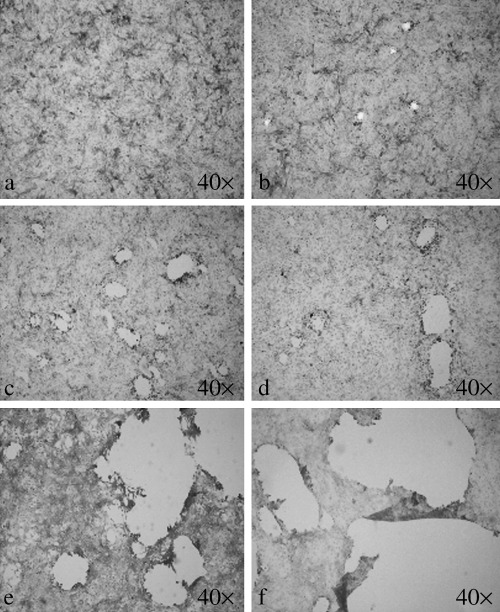
Level of monolayer damage associated with the applied peak pressure observed by light microscopy. (a) Control; (b) 1.2 MPa; (c) 4.0 MPa; (d) 7.0 MPa; (e) 13 MPa; (f) 16 MPa. (hematoxylin and eosin staining, original magnification 40×).
When the focused shock wave encounters the cover slide glass, both wave reflection and refraction occur. After the interaction, part of the incident shock wave is reflected back into the medium, while longitudinal and transverse stress waves are generated in the cover slide glass. A simple quantitative estimate of the wave interaction process based on the fundamentals of wave dynamics, by assuming that the wave incidence is normal at the interface, shows that 34% of the incident wave intensity is transmitted through the cover slide glass.( 12 , 13 , 14 ) The higher propagation speed of longitudinal (cL = 5840 m/s) and transverse (cS = 3460 m/s) waves in the cover slide glass than the sound speed in water (1509 m/s) cause longitudinal and shear head waves or leaky waves in water.( 15 ) For the thin cover slide glass plate, the leaky waves are much weaker than the incident and reflected shock waves, therefore their effects on the monolayer can be neglected.( 16 )
As a standard dose, 10 shock waves at a frequency of one discharge per second with a peak positive pressure of 16 MPa was used for the present experiments.
Cell morphology
Control ACHN cells exhibited a spindle‐shaped, fibroblast‐like appearance in the culture, observed by scanning electron microscopy. The flattened ACHN cells had long lateral cytoplasmic projections and a few microvilli on their upper surfaces. They strongly apposed the adjacent cells and had grown strictly anchorage dependent in the monolayer.
After shock wave exposure, based on severity of deformation in the treated cells, the monolayer was divided into three morphological areas, as shown in Fig. 5a.
Figure 5.
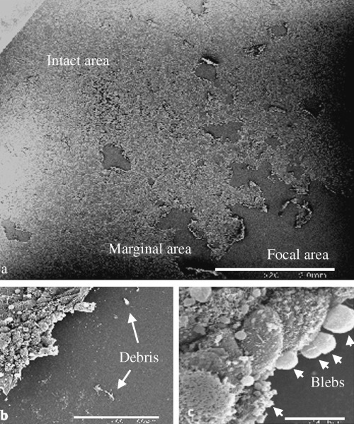
Morphological deformations in the shock wave treated monolayer observed by scanning electron microscopy: (a) Three morphological areas in the monolayer: focal, marginal and intact area (scale bar 2.0 mm); (b) the remaining cell fragments (arrows) on the slide glass within the focal area (scale bar 100 µm); (c) blebs (arrows) and wrinkles on the surfaces of the rounded cells within the marginal area (scale bar 10 µm).
-
1
Focal area: an area in the monolayer located at the focal zone of the generator, which received the maximum applied pressure. Almost all of the cells within this area were dislodged from the monolayer and released into the chamber. The remainder of the removed cells with different sized cell fragments were found still attached on the slide glass, indicated by arrows in Fig. 5b. Most of the detached cells were found as aggregated ruptured cell debris in the medium.
-
2
Marginal area: in the vicinity of the focal area, where the monolayer still remained on the slide glass, cells were partially detached from the substratum and exhibited a round appearance. Their surfaces were wrinkled and covered with blebs as they were retracted from the slide glass, as shown in Fig. 5c.
-
3
Intact area: with increased distance from the marginal area, the monolayer exhibited alteration neither in the morphology nor in the arrangement of the cells. Their distribution pattern was identical to the control monolayer.
Cell cytoskeleton
The control ACHN cells in the culture developed three‐dimensional latticework of the cytoskeletal proteins. Deformations of actin, tubulin and vimentin filaments in the shock wave treated cells were separately studied with respect to the location of the cells within the three morphological areas.
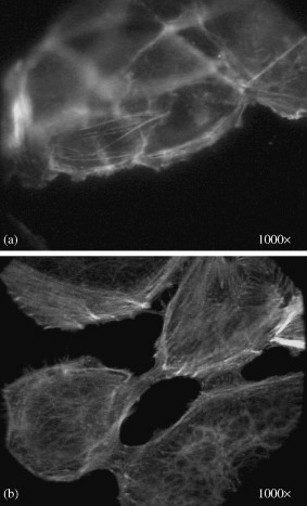
Actin filaments make different assemblies with various functions. Cell cortex, stress fibers and cytoplasmic actin filaments are actin‐rich networks in different regions of a cell. Cell cortex is a layer of short actin filaments cross‐linked into a strong network beneath the plasma membrane, which gives mechanical strength to the cell membrane and enables the cell to change its shape and to move. This can be seen at the peripheries of the control ACHN cells in Fig. 6a. Another actin assembly, the network of cytoplasmic actin with longer actin filaments oriented through the cytoplasm, is indicated by an arrow in Fig. 6a. The cytoplasmic actin filaments are believed to be essential for internal movements that occur in the cytoplasm. Stress fibers are temporary contractile bundles of long actin filaments and myosin. They usually insert at one end into the plasma membrane (at focal contacts) and at the other end into a second focal contact or into a meshwork of intermediate filaments that surrounds the cell nucleus (Fig. 6b).
Figure 6.
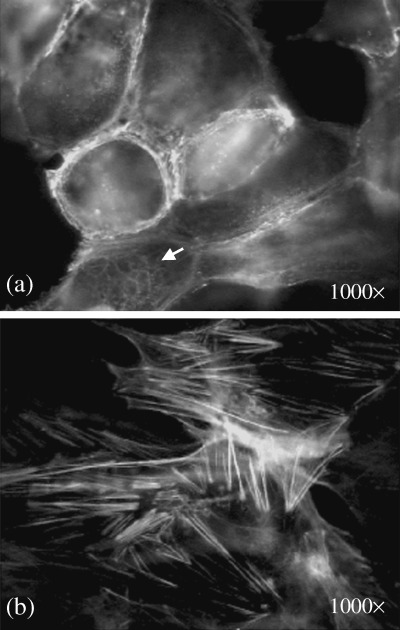
Immunofluorescence staining of a control monolayer with phalloidin‐fluorescein (FITC) antibody to actin filaments. (a) Cell cortex at the cell periphery contains short actin filaments. Arrow indicates the network of cytoplasmic actin filaments. (b) Long actin bundles of stress fibers at the lower surface of the cells (original magnification 1000×).
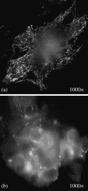
After treatment with shock waves, all of the cells were removed from the focal area in the monolayer. Thus, as detected by the antiactin fluorescent antibody, almost all of the focal area was negative for fluorescein, except for the remaining cell fragments on the slide glass that contained ‘broken’ actin filaments, as shown in Fig. 7a. The actin networks of the detached and released cells into the medium were totally depolymerized and were found in aggregates near the peripheries of the cells, as shown in Fig. 7b.
Figure 7.
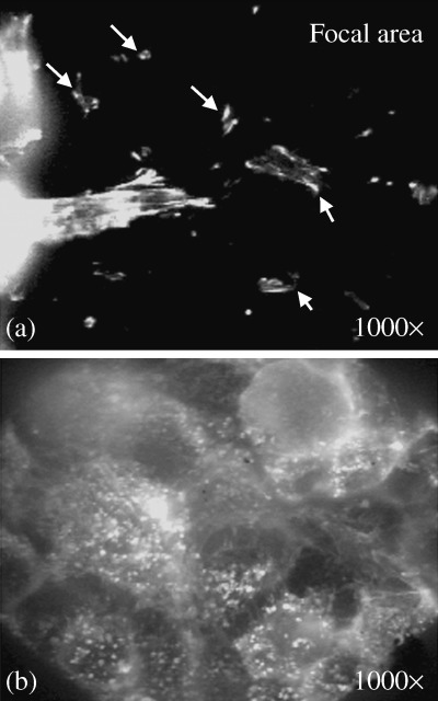
Immunofluorescence staining of the focal area with phalloidin‐fluorescein (FITC) antibody to actin filaments. (a) Remaining cell fragments on the slide glass (indicated by arrows) containing fragments of actin filaments. (b) Depolymerized actin filaments were aggregated at the periphery of spherical‐shaped cells detached from the substratum (original magnification 1000×).
Meanwhile, the passage of weakening shock waves and flow filed through the cell monolayer in the marginal area consequently caused a variety of actin network deformations. Discontinuity and ruptures in the cell cortex were interesting findings in this area, as shown in Fig. 8a,b. The cytoplasm of the retracted cells contained disorganized, shortened, thickened and aggregated actin filaments (Fig. 8c). The depolymerized cytoplasmic actin filaments retracted from the peri‐nuclear area toward the cell periphery and created a fluorescence‐negative zone at the center of the cells (Fig. 8d). Within the intact area, as expected, there was no detectable deformation of actin organization in the cells.
Figure 8.
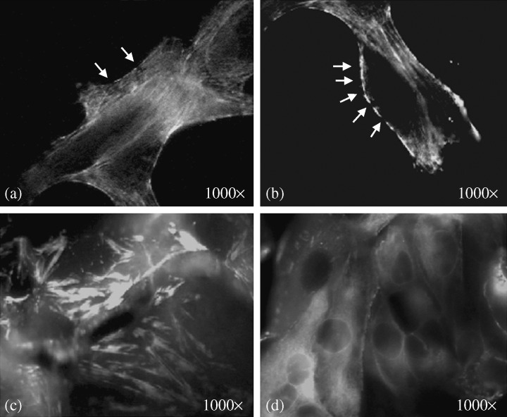
Immunofluorescence staining of the marginal area with phalloidin‐fluorescein (FITC) antibody to actin filaments. (a,b) Disrupted cell cortex at the cell periphery indicated by arrows. (c) Stress fibers were thickened, aggregated and shortened in the retracted cells. (d) Retraction of cytoplasmic actin filaments toward the cell periphery produced a fluorescence‐negative zone at the center of the cells (original magnification 1000 ×).
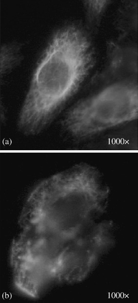
Reorganization of cytoskeletal actin filaments in the detached cells was compared under a fluorescence microscope with a group of control cells. Most of the shock wave treated cells recovered from the medium remained spherical‐shaped, even after 20 h in the culture. They did not develop any actin filament in their cytoplasm. However, there were few surviving cells that had flattened on the substratum 5 h after shock wave exposure. In respect to the pattern of actin reassembly, no significant differences were found between those few surviving cells and the control cells. In contrast, the partially retracted and rounded shock wave treated cells within the marginal area had flattened and started to reorganize actin filaments as early as 3 h after shock wave exposure. During the early hours of attachment and initial radial spreading, actin reassembly had mostly been concentrated in the cell cortex and large lamelipodia at the cell periphery. Few stress fibers were found in this early stage (Fig. 9a). Within a few hours after the cells settled back on the substratum, especially when they reached each other and started to stabilize their position, they established long actin filaments which criss‐crossed the cytoplasm. At this stage, as shown in Fig. 9b, their cytoskeleton became organized in patterns typical of well‐spread control cells, including the development of stress fibers.
Figure 9.
Development of actin filaments during spreading of shock wave treated ACHN cells (a human renal carcinoma cell line) fixed and stained (a) after 3 h; (b) after 20 h (original magnification 1000×).
Tubulin appeared thinner and better defined than actin, running mainly along the cellular long axis. The tubulin network of a control cell is shown in Fig. 10a. In the shock wave treated cells detached from the monolayer, almost all of the cytoplasmic microtubule filaments were depolymerized (Fig. 10b). The cytoplasm of these cells contained densely stained fluorescent structures, believed to be centrioles with more stable microtubules. Tubulin filaments in the marginal area were either depolymerized or remained unchanged in the cells. There were no gradient deformations of tubulin filaments; similar to that found for actin filaments. In the intact area, as expected, no deformation of the tubulin network was detected in the monolayer.
Figure 10.
Immunofluorescence staining with anti β‐tubulin antibody: (a) control ACHN cell (a human renal carcinoma cell line); (b) shock wave treated cell (original magnification 1000×).
After reculturing the detached cells or keeping the shock wave treated monolayers in the medium for 5 h and staining them with antitubulin antibody, the lost tubulin filaments were repolymerized in the leading edge of the surviving cells, identical to the control cells (data not shown).
Vimentin intermediate fibers in the control cells were found in great density around the nucleus that radiated out into the cell periphery in fine lace‐like threads, as shown in Fig. 11a.
Figure 11.
Immunofluorescence staining with antivimentin antibody: (a) control ACHN cell (a human renal carcinoma cell line); (b) shock wave treated cell (original magnification 1000×).
After shock wave treatment, the network was deformed due to the morphological deformations of the treated cells; however, its fibrillar structure remained unchanged throughout the cytoplasm of the cells. The fibrillar structure of vimentin can be seen even in the cell debris, as shown in Fig. 11b.
Discussion
Shock waves are used to treat two different categories of disease. Lithotripsy is the principle application of shock waves. Beyond stone fragmentation, shock waves have been applied in the treatment of bone and tendon disorders. Combined cancer therapies including shock waves have stimulated great interest in recent years.( 17 , 18 , 19 ) Shock wave effects on tumor cells have been investigated in various in vivo and in vitro studies.( 1 , 5 ) However, there are still many questions concerning the effects of shock waves and their mechanisms.
A shock wave is a single pressure pulse of microsecond duration with a peak pressure of several hundred atmospheres, followed by a tensile pressure with a lower maximum and longer duration. For clinical applications, shock waves generated by different lithotripters are administered as single strong pulses at a frequency of one or two discharges per second. The peak positive pressure and the peak negative pressure amplitude in the focus vary from 30–120 MPa and 5–15 MPa, respectively. In the present study, the results indicated that monolayer damage could be achieved under a wide range of shock wave pulse intensities (0.002–0.041 mJ/mm2), which is in the lower order of pulse intensities of 0.03–1.0 mJ/mm2 used for extracorporeal shock wave therapies.( 11 )
This study presents the initial results of the mechanical effects of shock waves on an in vitro model system comprised of the cell monolayer. The most important question arising in any in vitro study using tissue culture concerns whether or not the cells under study behaved as they would in the intact tissue. Here, cells in the cultures provided one layer of a three‐dimensional network of the cytoskeletal organizations, which is an advantage of the system compared with conventional histological sectioning methods. Also, by keeping the intracellular organelles in their position, the fibrillar structures make the monolayer a suitable system for further investigations of shock wave effects at the cellular level. Cells in the monolayer develop cell‐cell and cell‐substratum adhesions at their ventro‐lateral edges, which are missing in cell suspension. To take into account all these factors, cells in the monolayer system are assumed to have similar physical properties to those in tissue. Thus, the morphological deformations in the monolayer system are very similar to those reported from an ex vivo experiment by Seidl et al. in 1994.( 20 ) However, due to differences in acoustic impedance between the cover slide glass and the medium, the pattern of the applied energy differed between the in vitro and in vivo studies.
Cell injury associated with shock waves is commonly conferred to cavitation. The tensile pressure pulse following the shock wave generates cavitation. Occurrence of cavitation was associated with signs of damage to the monolayer, as shown in Fig. 4b. Bubble dynamics is a chain of events which can be described as an initial growth of the bubble, followed by the beginning of bubble collapse, and the final collapse phase which forms a jet towards the rigid boundary. During all three phases, outward and inward streaming of the liquid surrounding the bubble can subject the cells in the monolayer to shear stress. However, high velocity water jet streams generated from the final phase of collapsing cavitation bubbles produces the main shear stress responsible for cell detachment.( 7 )
The retracted cells within the marginal area are covered with the blebs on their surfaces after the shock waves (Fig. 5c). Blebs are almost hemispherical herniations of the cell surface, which bulge out rapidly and fill with fluid from the cytoplasm. Holmes et al.( 21 ) have also reported this phenomenon as extrusion of the cytoplasm from focal disruption in the plasma membrane of shock wave treated neutrophils. Because the treated cells were immediately fixed after shock wave exposure, the cultural condition was not an important factor in bleb formation in this experiment. Bleb formation was interpreted as clear evidence for separation of the plasma membrane from the cytoskeleton. The explanation for blebbing appears to be that the shock waves increase the intracellular pressure; directly by compressing the cell from the outside and/or indirectly by rupturing the cytoskeletal fibers. When pressure within the cell was raised, it could be momentarily released by expansion of areas in the cell membrane in the form of blebs. The expanding areas may have been produced independently of, or in concert with, the damaged cell cortex. As discussed, during all phases of cavitation the monolayer is subjected to shear stress. It seems that the final picture of the shock wave effects on the treated cells, including bleb formation, is drawn by the effect of the final dominant shear stress. However, the effects of the previous forces, including the negative pressure caused by the beginning of the bubble collapse which causes an inward streaming of the liquid surrounding the bubble, cannot be ruled out.
In shock wave induced gene or drug delivery, extrusion of the cytoplasm during bleb formation may be a factor that reduces the efficacy of the therapy. More studies are required to determine its effect in detail.
In most non‐muscle cells, microfilaments and intermediate filaments are associated with the plasma membrane and play key roles in the determination of cell shape. Electron microscopic observations of actin filaments have shown that both assembly and disassembly occurs preferentially at one end of the filament, called the plus‐end, which points toward the membrane to which they normally are attached.( 22 ) As a consequence of cell attachment to a substratum, any tension generated on these filaments exerts a pull on the plasma membrane. With respect to this, it is concluded that the morphological deformations in the monolayer caused by shock waves were associated with the depolymerization of the underlying cytoskeletal organizations.
Biomechanical effects of cavitation are believed to be the main cause of the biological effects of shock waves in the monolayer.( 7 ) The violent collapse of the cavity can result in the formation of reactive oxygen species (ROS).( 23 ) Because the diffusion length of free radicals in aqueous solutions is between 0.1 and 1 µm and the generation is concentrated in the center of the collapsing cavity, a recombination of the free radicals to hydrogen peroxide is very likely.( 23 ) However, studies have shown that most of the effects caused by ROS are related to intracellularly generated free radicals.( 24 ) Endl et al.( 25 ) and Feril et al.( 26 ) have measured intracellularly and extracellularly generated ROS during acoustic wave exposures using radical sensitive dyes. They found no indication of acoustic wave induced intracellular free radicals. The evidence reviewed above indicates that biochemical effects of shock waves are not considered to be possible factors for the cytoskeletal deformation of the treated monolayer in the present study.
One of the interesting cytoskeletal deformations following shock wave exposure was the disrupted actin bundles in the cell cortex (Fig. 8a,b). The disrupted cell cortex strongly indicated the presence of weekly supported areas in the cell membrane of the shock wave treated cells. However, as pores were not directly observed on the cell surfaces because of their transient characteristics, the disrupted cell cortex can indirectly support the pore formation theory by which shock wave induced gene transfection has been explained.( 23 , 27 , 28 ) Whether or not the disrupted cell cortex was produced by an extrinsic factor, like shear stress generated by the jet phenomenon or increased intracellular pressure, remains to be determined.
It is known that the ventral surface of adherent cells at a limited number of places, but not the entire surface, comes in very close contact (<10 nm) with the substrate, known as focal contacts.( 29 ) Focal contacts are the sites where a few stress fibers usually insert into the membrane. Here, the remaining cell fragments on the cover slide glass containing short actin filaments are the focal contacts of the removed cells from the monolayer (Fig. 7a). The direct effect of shock waves along with fluid streaming caused by bubble collapses can cause strain by compression and tension when waves scatter in the heterogeneous medium.( 7 , 30 ) Apparently, these forces pull the cell body while the focal contacts still adhere to the substratum. Shearing can be produced when the shock waves are passing through these sites of firm adhesion. Strain and fatigue can finally rupture the stress fibers when cells are detached from the substratum. Because the cell membrane is involved in the structure of the focal contacts, it can also be torn apart due to the shearing. In the case of minor damage, the created defects left in the cell membrane will immediately reseal without any effect on cell viability. However, in the case of extensive damage to the membrane, the cell will eventually die. The process by which the exposure results in rupture of the plasma membrane can complete the picture of shock wave induced cell damage in adherent cells.
Microfilaments such as tubulin are essential for cell transportation and mitosis/meiosis. Shock wave induced acute but transient depolymerization of the tubulin filaments (Fig. 10b) can temporally influence cell division in the treated cells. This may explain the observed delay in the growth rate of the recultured detached cells from the monolayer.
Fibrous subunits of vimentin associate site by site in overlapping arrays, and its major function is to resist mechanical stress.( 29 ) The filaments can be easily deformed, but resist larger forces better than the two other fibers, as shown in this experiment (Fig. 11b).
Transient effects of the shock waves on the cytoskeleton did not produce long‐term effects on repolymerization and the reorganization ability of the surviving cells, either those detached from the substratum or those remaining on the slide glass (Fig. 9a,b). Seidl et al. described the development of stress fibers in human vascular endothelial cells immediately after shock wave exposure.( 20 ) In contrast, in this experiment stress fibers were found at the later stage of the adherent. This discrepancy can be explained by considering the time interval before fixation and also possible applied tensions during handling of the endothelial cells in Seidl et al.'s experiment. When cells are removed from the substratum, they become spherical and subsequently stress fibers disappear from their cytoplasm (Fig. 7b).( 22 , 29 ) Development of stress fibers, like development of focal contacts and typical cellular morphology, takes several hours (Fig. 9a,b). Thus, cells cannot form stress fibers simultaneously when they are detached from the substratum.
In conclusion, it has been shown that the monolayer is a suitable system for further investigation of the effects of shock waves on subcellular structures, such as the cytoskeleton. Morphological deformations of the treated cells were shown to be associated with their cytoskeletal disorganizations. The effects were found to be transient and reversible in the surviving cells. Taken together, the results support the shear stress theory as the main mechanism of shock wave induced membrane damage in the adherent cells.
Shock wave generated cell cortex disassembly creates a golden period for introducing some large molecular size chemotherapeutic drugs or genes into treated tumor cells. Understanding the mechanism and the period of the damage in the cytoskeleton of shock wave treated cells can help in the design of a more sufficient therapeutic plan for combining chemotherapy and shock waves. Because the cell membrane in the treated cells is not fully supported by the cell cortex during the golden period, submitting tumor cells to shock waves before combining with chemotherapy, can significantly increase the effects of chemotherapeutic agents.( 31 )
Optimizing the amount of chemotherapeutic agents and the energy level of applied shock waves might be another application of the present results which would minimize the side‐effects of chemotherapy and shock wave treatment.
Shock wave induced cytoskeletal deformations raise several interesting possibilities. One possible interpretation of the results is that cytoplasmic components of the treated cells might be displaced due to micro streaming of the cytoplasm, for example, during bleb formation. The other possibility is that intracellular transportation of vesicles and particles, which move along ‘tracks’ of cytoskeletal filaments, would be temporarily paralyzed. The biological significance of these effects warrants further investigation. Further investigation of subcellular deformations would bring us closer to understanding the mechanism of shock wave induced cell damage in adherent cells.
References
- 1. Oosterhof GON, Smits GA, Hj deRuyter JE et al. The in vitro effect of electromagnetically generated shock waves (Lithostar) on the Dunning R3327 PAT‐2 rat prostatic cancer cell‐line. Urol Res 1989; 17: 13–19. [DOI] [PubMed] [Google Scholar]
- 2. Russo P, Stephenson RA, Mies C et al. High energy shock waves suppress tumor growth in vitro and in vivo. J Urol 1986; 135: 626–8. [DOI] [PubMed] [Google Scholar]
- 3. Brauner T, Brummer F, Hulser DF. Histopathology of shock wave treated tumor cell suspensions and multicell tumor spheroids. Ultrasound Med Biol 1989; 15: 451–60. [DOI] [PubMed] [Google Scholar]
- 4. Brummer F, Brenner J, Brauner T, Hulser DF. Effect of shock waves on suspension and immobilized L1210 cells. Ultrasound Med Biol 1989; 15: 229–39. [DOI] [PubMed] [Google Scholar]
- 5. Endl E, Steinbach P, Scharfe J, Fickweiler S, Worle K, Hofstadter F. Cell‐type‐specific response to shock waves of suspended or pelleted cells as analyzed by flow cytometry or electrical cell volume determination. Ultrasound Med Biol 1996; 22: 515–25. [DOI] [PubMed] [Google Scholar]
- 6. Steinbach P, Hofstaedter F, Nicolai H, Rossler W, Wieland W. In vitro investigations on cellular damage induced by high energy shock waves. Ultrasound Med Biol 1992; 18: 691–9. [DOI] [PubMed] [Google Scholar]
- 7. Ohl C‐D, Wolfrum B. Detachment and sonoporation of adherent HeLa‐cells by shock wave‐induced cavitation. Biochim Biophys Acta 2003; 1624: 131–8. [DOI] [PubMed] [Google Scholar]
- 8. Delius M. Medical applications and bio‐effects of extracorporeal shock waves. Shock Waves 1994; 4: 55–72. [Google Scholar]
- 9. Miller MW. Gene transfection and drug delivery. Ultrasound Med Biol 2000; 26 (Suppl. 1): S59–S62. [DOI] [PubMed] [Google Scholar]
- 10. Yanagida Y, Iwama N, Kosaku H, Okazaki K. Effect of controlled sound pressure field on fragmentation in piezoelectric extracorporeal shock wave lithotripsy. Jpn J Appl Phys 1994; 33: 3151–4. [Google Scholar]
- 11. Ueberle F. Pressure pulses in extracorporeal shock wave lithotripsy and extracorporeal shock wave pain therapy. In: Srivastava RC, Leutloff D, Takayama K, Groenig H, eds. Shock Focusing Effect in Medical Science and Sonoluminescence. Berlin: Springer, 2003; 179–210. [Google Scholar]
- 12. Brekhovskikh LM. Waves in Layered Media. New York: Academic Press, 1960. [Google Scholar]
- 13. Brekhovskih L, Goncharov V. Mechanics of Continua and Wave Dynamics. Berlin: Springer, 1985. [Google Scholar]
- 14. Saito T, Voinovich PA, Nakagawa A, Hosseini SHR, Takayama K, Hirano T. On the efficiency of Gore‐Tex layer for brain protection from shock wave damage in cranioplasty. Rev Sci Instrum 2004; 75 (11): 4789–96. [Google Scholar]
- 15. Voinovich P, Merlen A. Two‐dimensional unstructured elastic model for acoustic pulse scattering at solid–liquid interfaces. Shock Waves 2002; 12: 421–9. [Google Scholar]
- 16. Watanabe K, Sano Y, Mukai N, Toriaki H, Sasoh A. Influence of metal plate thickness on underwater pressure waves induced by laser peening. Sci Tech Energetic Materials 2004; 65: 161–6. [Google Scholar]
- 17. Lauer U, Burgelt E, Squire Z. Shock wave permeabilization as a new gene transfer method. Gene Ther 1997; 4: 710–5. [DOI] [PubMed] [Google Scholar]
- 18. Delius M, Adams G. Shock wave permeabilization with ribosome inactivating proteins: a new approach to tumor therapy. Cancer Res 1999; 59: 5227–32. [PubMed] [Google Scholar]
- 19. Feril LB Jr, Kondo T, Umemura S, Tachibana K, Manalo AH, Riesz P. Sound waves and antineoplastic drugs: the possibility of an enhanced combined anticancer therapy. J Med Ultrasonics 2002; 29: 173–87. [DOI] [PubMed] [Google Scholar]
- 20. Seidl M, Steinbach P, Worle K, Hofstaedter F. Induction of stress fibers and intercellular gaps in human vascular endothelium by shock waves. Ultrasonics 1994; 32: 397–400. [DOI] [PubMed] [Google Scholar]
- 21. Holmes RP, Yeaman LD, Taylor RG, McCullough DL. Altered neutrophils permeability following shock wave exposure in vitro. J Urol 1992; 147: 733–7. [DOI] [PubMed] [Google Scholar]
- 22. Darnell J, Lodish H, Baltimore D. Molecular Cell Biology, 2nd edn. New York: Scientific American Books, 1990. [Google Scholar]
- 23. Gambihler S, Delius M, Ellwart JW. Permeabilization of the plasma membrane of L1210 mouse leukemia cells using lithotripter shock waves. J Membr Biol 1994; 141: 267–75. [DOI] [PubMed] [Google Scholar]
- 24. Ward JF. DNA damage produced by ionizing radiation in mammalian cells. Identities, mechanisms of formation, and reparability. Prog Nucl Acid Res Molec Biol 1988; 35: 95–123. [DOI] [PubMed] [Google Scholar]
- 25. Endl E, Steinbach P, Hofstadter F. Flow cytometric analysis of cell suspensions exposed to shock waves in the presence of the radical sensitive dye hydroethidine. Ultrasound Med Biol 1995; 21: 569–77. [DOI] [PubMed] [Google Scholar]
- 26. Feril LB Jr, Kondo T, Cui ZG et al. Apoptosis induced by the sonomechanical effects of low intensity pulsed ultrasound in a human leukemia cell line. Cancer Lett 2005; 221: 145–52. [DOI] [PubMed] [Google Scholar]
- 27. Leoning SA, Mardan AH, Holmes J, Lubarroff DM. In vivo and in vitro effects of shock waves on Dunning prostate tumors. Proceeding of the American Urological Association. J Urol 1988; 139: 303A. [Google Scholar]
- 28. Feril LB Jr, Kondo T. Biological effects of low intensity ultrasound: the mechanism involved, and its implications on therapy and on biosafety of ultrasound. J Radiat Res 2004; 45: 479–89. [DOI] [PubMed] [Google Scholar]
- 29. Alberts B, Bray D, Lewis J, Raff M, Roberts K, Watson JD. Molecular Biology of the Cell, 2nd edn. New York: Garland Publishing, 1994. [Google Scholar]
- 30. Howard D, Sturtevant B. In vitro study of the mechanical effects of shock‐wave lithotripsy. Ultrasound Med Biol 1997; 23: 1107–22. [DOI] [PubMed] [Google Scholar]
- 31. Prat F, Sibille A, Luccioni C et al. Increased chemocytotoxicity to colon cancer cells by shock wave‐induced cavitation. Gastroenterology 1994; 106: 937–44. [DOI] [PubMed] [Google Scholar]