Abstract
This study proposes a novel method for reattachment of the trochanteric slide osteotomy. The strength of this new fixation system was compared to established configurations. Fifteen sawbone femurs were used. Our configuration used cables above and below the lesser trochanter with a third cable around the shaft of the femur while passing the loose ends through the inferior hole of the cable grip. Displacement of the trochanter was measured with increasing load. Force required for catastrophic failure was also measured. The 3-cable construct resulted in significantly less displacement with increasing load and required a larger force to cause failure (1 cm and 2 cm). We theorize that our configuration produces a biomechanically stronger construct than previously used methods.
Keywords: cable grip, trochanteric osteotomy, slide osteotomy
The trochanteric “slide” osteotomy (TSO) is a common approach to the hip joint for arthroplasty patients who require a more extensive surgical exposure. Unlike the standard trochanteric osteotomy described by Charnley [1], the TSO retains the origin of the vastus lateralis that naturally resists the pull of the hip abductors [2,3] preserves vascularity and the trochanteric segment.
The TSO is often used in revision arthroplasty to gain better exposure to the hip joint. Often, removal of hardware can be a tremendous challenge due to inadequate exposure. The TSO can also be used for difficult primary total hip arthroplasty requiring wider exposure, such as in patients with a history of slipped capital femoral epiphysis or developmental dysplasia. The TSO is not used routinely in total hip arthroplasty, as the incidence of complications requiring repeat surgery has been reported to be as high as 28% [4].
Nonunion of the trochanter remains the most common complication associated with the TSO and can result in persistent pain, increased risk of dislocation, and a Trendelenburg gait pattern [5]. After any total hip arthroplasty, the hip abductors are typically stretched to some degree, due to lengthening of the limb and/or increased offset of the prosthesis. This can make anatomical reattachment of the greater trochanter difficult and can increase the load on the fixed fragment.
The rate of nonunion of the greater trochanter, when using a standard wire or cable fixation techniques, has been reported to be as high as 37.5% [6]. In contrast, a recent series of 223 total hip arthroplasties that used the Dall-Miles cable grip system reported a 91% union rate of the greater trochanter [7]. In this study, the cable grip system was used for all cases, though several different techniques were used to apply the cables.
Biomechanically, initial trochanteric fixation with the Dall-Miles cable grip system has been shown to be superior to the Charnley cable configuration or other cable fixation techniques [8]. The Dall-Miles cable grip system provides a stiffer construct than wire or cable fixation systems alone. Even with cable grip systems, trochanteric nonunion is still a significant problem [7]. The adequacy of initial fixation is believed to significantly influence nonunion rate. However, there is no consensus as to the best method for implementing the Dall-Miles cable system. In every configuration, cable tensioning is crucial as is a strategy to limit cable slippage and migration of the greater trochanter. The most commonly used methods to reduce cable migration include placing the cables above and below the lesser trochanter or passing the cables through bone tunnel in the lesser trochanter [7–9]. The above and below configuration is quickest, but the tunneling configuration is believed to better limit cable migration. In the series of McCarthy et al [7], the cables were passed medially through bone tunnels in the lesser trochanter, through cortical bone lateral to the prosthesis, or both medial and lateral to the prosthesis.
Recently, we have begun to use an alternate cable configuration. We believe it reduces the trochanteric migration compared to the “above and below” or “tunneling” methods. Three cables are used as follows: one placed above the lesser trochanter, one below the lesser trochanter, and a third that is wrapped around the shaft of the femur below the lesser trochanter, crimped, and then passed through the distal-most hole of the Dall-Miles cablegrip. This third cable acts as a tether and prevents proximal migration of the greater trochanter. This study was performed to compare the stability of this new configuration to the previously used above and below and tunneling configurations. We hypothesized that our 3-cable technique would significantly improve initial fixation strength and stability when compared to these 2 established techniques.
Materials and Methods
Comparison of the 3 cabling techniques was performed using 15 third-generation composite short glass fiber–reinforced epoxy femurs designed specifically for biomechanical testing (part no. 3306. Sawbones. Pacific Research Laboratories, Vashon Island, WA). Composite femurs were used to reduce the confounding effects of wide interspecimen variability typically seen with human cadaver bones. Third generation composite femurs were found by Heiner et al [10] to have comparable structural properties to second-generation composite femurs under bending and torsional loads but significantly less variability under axial loading. Axial strain distribution was observed to be similar to what is seen in human femurs, but variability in stiffness was less compared to the latter. Five femurs were used for each cabling technique.
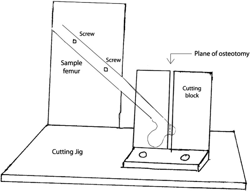
To test our hypothesis, we fabricated a platform from aluminum that would allow us to perform our osteotomy and test the specimens under uniform conditions (Fig. 1). The femurs were mounted on our testing platform by placing 2 set screws through the shaft of the femur. The femoral head was placed in a 1 cm recessed hemisphere that was contoured to match the specimen. The 2 set screws were tightened down to prevent any movement from the femur. The fabricated osteotomy guide was used to make a standard osteotomy at 45° to the long axis of the femur, replicating the pull of the abductors. This ensured that all of our osteotomy specimens were uniform in dimension and angle. We then reattached our osteotomized greater trochanter to the femur using the Dall-Miles cable grip with 3 of the 3 cable configurations as described below.
Fig. 1.
A schematic of the cutting jig with a sample femur demonstrating the plane of osteotomy of the greater trochanter.
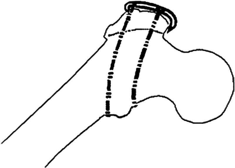
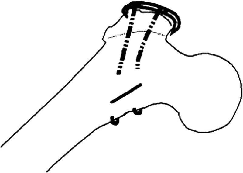
In the first configuration (configuration 1), 2 cables were used—1 above and 1 below the lesser trochanter (Fig. 2). Two cables were also used for the second configuration (configuration 2). However, in this case, they were passed medially through 2.5-mm diameter holes drilled from anterior-posterior through the lesser trochanter (Fig. 3).
Fig. 2.
Configuration 1.
Fig. 3.
Configuration 2.
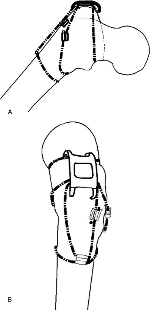
In our configuration (configuration 3), 3 cables were used. One was placed above the lesser trochanter and passed through the proximal holes of the cable grip. The second cable was placed below the lesser trochanter and passed through the middle pair of holes in the cable grip as is shown in Fig. 4A. The third cable was wrapped circumferentially around the femoral shaft, and the 2 free ends were passed through a crimp that was placed on the lateral aspect of the femur. Then the superior free end of the cable was passed through the inferior most pair of holes in the cable grip to engage the cable grip and secure it inferiorly. This cable end that was passed through the cable grip was then crimped with the other inferior free end. This last crimp was placed between the grip and circumferential wire as is shown in Fig. 4B. Overall, 2 crimps were used for the third cable, and the crimps were placed at 90° to each other on the lateral aspect of the femur. In all cases, the cables were tensioned to 50 lb before being crimped at the cable grip.
Fig. 4.
(A and B) Configuration 3.
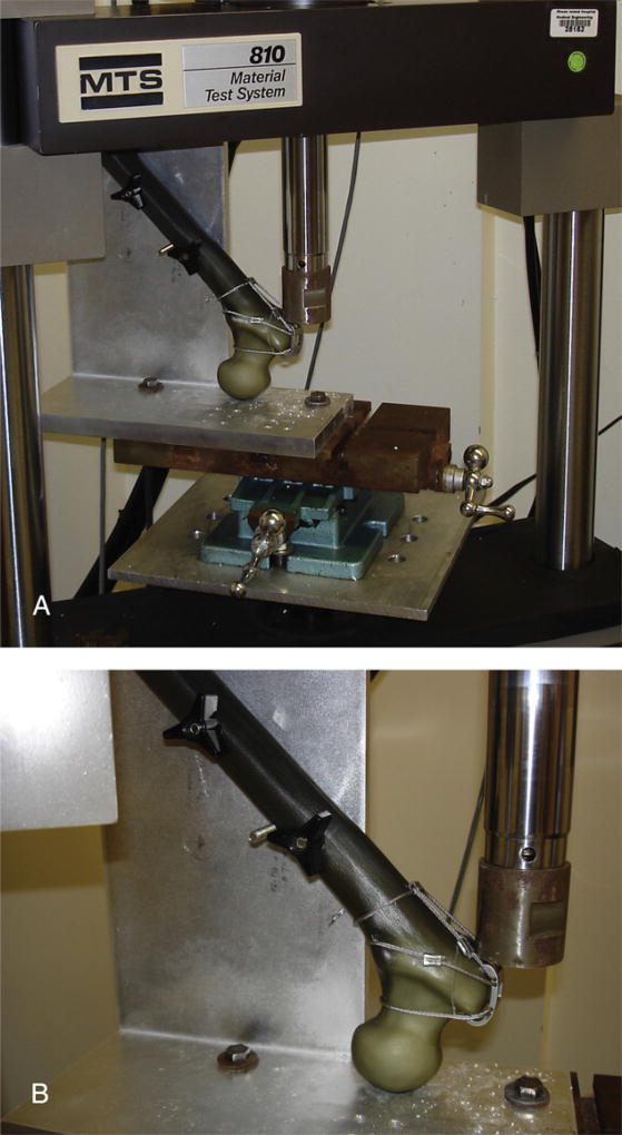
The reattached trochanteric fragments were loaded in shear with a force directed parallel to the plane of the osteotomy, simulating pull of the abductors. To do so, the femurs were inverted and mounted into a servohydraulic load frame Instron (Model 810, MTS Systems Corporation, Eden Prairie, MN) using a specially designed jig (Fig. 5A, B). The jig held the diaphyseal axis at an angle of 45° to the vertical and captured the femoral head in a congruent, 1-cm-deep spherical recess.
Fig. 5.
(A) Photograph of the Instron machine with a sample femur loaded to demonstrate plane of application of force on the osteotomized fragment. (B) Photograph demonstrating direction of force application on the osteotomized fragment.
The force applied across the greater trochanter when a person rises from a chair has been reported to reach as high as 4× body weight [9]. With this in mind, we began by loading the femurs with 700 N, equivalent to 70 kg, at 1 Hz for 10 cycles. We then increased the force to 1400 N for 10 cycles, with our force ranging from 700 N to 1400 N. We then increased the force again to 2100 N for 10 cycles, and then to 2800 N for 10 cycles, equivalent to 4× the body weight of a standard 70-kg man. If the specimen was able to withstand 10 cycles of 2800 N force, we then loaded the specimen to catastrophic failure (defined as displacement of ≥2 cm with sawbone fracture or cable failure as defined below) at an applied displacement of 1 mm/s. During testing, applied load and actuator displacement were recorded at 10 Hz with a digital data acquisition system. Actuator displacement and trochanteric fragment displacement were considered to be coequal.
As interfragmentary motion is the main predictor of nonunion, motion of the affixed fragment was the main outcome variable.
Clinical failure has been defined in the literature as migration of the osteotomized fragment of 1 cm or more [5,8]. However, the literature does not show a consensus on this distance [9]. Moreover, Amstutz [5] showed in his study that abductor weakness was directly correlated to the amount of displacement of the greater trochanter. Clinically, abductor weakness was demonstrated when the greater trochanter migrated to 2 cm or more. Therefore, migration to 1 cm and 2 cm was used as an end point to measure deforming forces. Implant clinical failure was defined as displacement of the trochanter of 1 cm or more, whereas catastrophic failure as displacement of 2 cm or more of a fracture involving implant and trochanter [5,8,9]. Accordingly, for each specimen, we recorded the force at 1 cm and 2 cm of displacement. A P value of .05 or less was considered to be statistically significant for all compared results.
Results
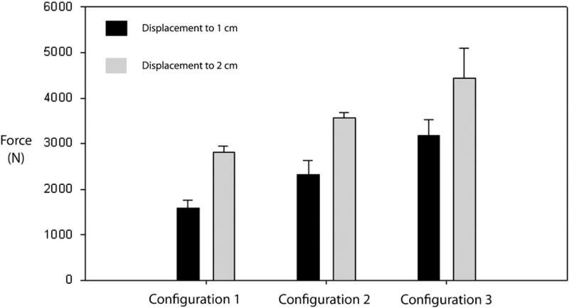
All specimens in configurations 1, 2, and 3, upon cyclic loading, exhibited 1 cm of displacement with increasing displacement force (Fig. 6) during catastrophic failure testing. Configuration 3 required the largest average amount of force (3176 ± 344.9 N) to displace the construct by 1 cm. This was statistically significantly higher when compared to the other 2 constructs. Configuration 2 required less average force (2325 ± 315.5 N) to displace to 1 cm when compared to configuration 3 (P < .01). Configuration 1 required the least amount of force to displace to 1 cm (1585 ±165 N) when compared to configurations 2 and 3 (P < .01 and P < .005, respectively). Hence, there was a statistically significant difference in amount of force required to displace by 1 cm between configurations 1, 2, and 3.
Fig. 6.
Force applied to displace to 1 cm (black) and 2 cm (gray).
Similar results were obtained when force requirements to displace to 2 cm were measured (Fig. 6). Configuration 3 required the highest force (4440 ± 654 N), when compared to the 2 other configurations, and this result was statistically significant (P < .001). Configuration 2 required a lower force (3556 ± 119 N) to displace to 2 cm when compared to configuration 3 (P < .001) but a statistically higher force (P < .001) when compared to configuration 1. Configuration 1 required the lowest force (2802 ± 143.8 N) to displace to 2 cm when compared to both configurations 2 and 3 that was statistically significant (P < .001).
Cyclic Loading
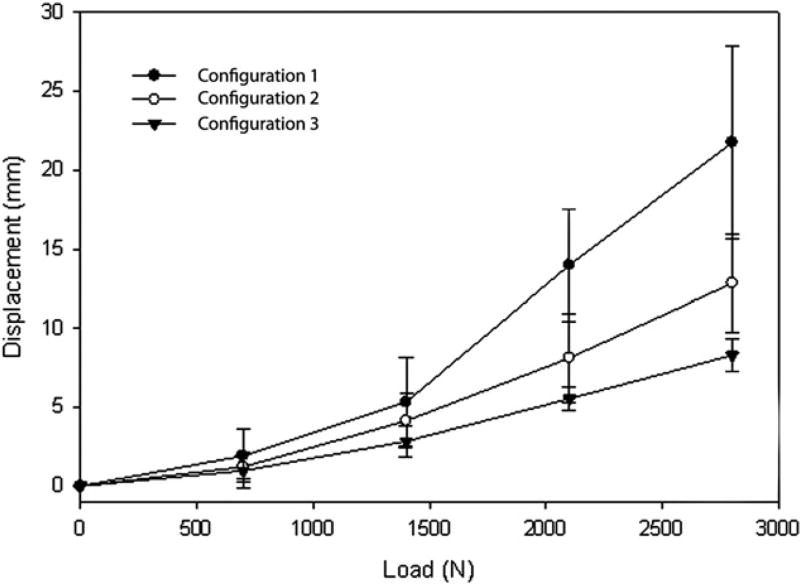
When analyzing displacement of each configuration at different loads, configuration 3 displaced the least at each loading force, whereas configuration 1 displaced the most (Fig. 7). The trochanter in configuration 3 displaced an average of 0.98 mm with the initial load of 700 N and continued to displace with each increase in load in a linear fashion. The trochanter in configuration 1 displaced an average of 1.92 mm with the initial load of 700 N. It proceeded to displace with each increase in load in a linear fashion but to a greater degree as compared to configurations 2 or 3. The trochanter in configuration 2 displaced an average of 1.22 mm with the initial load of 700 N and proceeded to displace with each increase in load in a linear fashion as well. There was a statistically significant difference between configurations 1 and 3 with regard to millimeters of displacement (P < .001 at 700 and 1400 N and P < .005 at 2100 and 2800 N, respectively) with configuration 3 displacing a shorter distance at each force increment as compared to configuration 1. There was no statistically significant difference seen between configurations 1 and 2 (P > .05 at all force increments) or between configurations 2 and 3 (P > .05 at all force increments).
Fig. 7.
Displacement of construct with increasing force being applied.
Discussion
Reattachment of the greater trochanter after osteotomy is associated with a high rate of nonunion and hardware failure [4]. Complication rates have been reported to be as high as 17.5% [11] with the various techniques used. Union rates have improved substantially with the use of the Dall-Miles cable grip system, which has been shown to deliver a significantly stronger repair as compared to various suture, wire, or cable techniques alone [8]. McCarthy et al [7] had a 91% union rate in their series with a mean of 6-year follow-up in 223 cases when the cable grip system was used.
Traditionally, cables are passed above and below the lesser trochanter when using the cable grip. This configuration relies heavily on the more distal cable that passes underneath the lesser trochanter [7]. If the osteotomized fragment starts to migrate superiorly, the cable that is placed proximal to the lesser trochanter has a tendency to migrate over the calcar and onto the femoral stem. This occurred during testing of configuration 1 in our study in 2 of 5 specimens. Moreover, the contact of the rough cable surface on the femoral stem can cause massive particulate generation. Therefore, this configuration can hypothetically result in loosening and possible catastrophic failure of the construct. Hence, many surgeons prefer to pass the cables through bone tunnels in the lesser trochanter to prevent this migration.
In configuration 2, the placement of bone tunnels can be technically challenging. A tunnel can be placed too far laterally that can allow the cable to come into contact with the stem or cement mantle and cause particle generation. In addition, the tunnel can also be placed too superficially and create a stress riser in the calcar, thus increasing the risk of periprosthetic fracture. In 2 of our specimens, cables passed through the lesser trochanter failed when an intertrochanteric fracture developed, starting at the bone tunnel and propagating cephalad. Hence, this configuration, although preventing migration of the cables, does have other disadvantages that makes it a less favorable method of fixation of the greater trochanter.
In configuration 3, none of the constructs failed by either superior migration of the cables or involved intertrochanteric fractures. Furthermore, this configuration also required the largest force to undergo both clinical failure (1 cm) and catastrophic failure (2 cm) of the osteotomy when compared to the other 2 configurations. Also, our construct displaced the least distance with increasing load application as compared to the other 2 configurations. This result was statistically significant when compared to configuration 1 but not configuration 2. In 3 of our specimens, the greater trochanter did not displace at all with increasing force and had catastrophic sawbone fracture or cable breakage at very high loads (approximately 4697 N). We believe that adding a third cable improves biomechanical stability of the cable grip by securing it to the femur and improves resistance to deforming forces.
There are some biomechanical advantages to our construct. The cable grip configuration anchors the construct to the femur, preventing the repair from escaping proximally. It does not compromise the compressive forces across the osteotomy as there are 2 cables directed perpendicular to the cut. Furthermore, as it does not use bone tunnels, it reduces operative time spent in tunnel preparation and further reduces the risk of periprosthetic fracture around these tunnels. Hence, we propose that the 3 cable fixation method is a biomechanically superior construct for reattachment of a trochanteric slide osteotomy when compared to the other 2 configurations.
There are a few disadvantages in our configuration. Certainly, placement of the third cable does make construction of configuration 3 slightly longer than developing configuration 1. It is unclear as to whether our construct takes a longer period to develop as compared to configuration 2 that involves making bone tunnels. Moreover, although it is not technically challenging to manipulate the third cable, it is important to crimp the third cable on the shaft of the femur before passing one of the free ends through the inferior holes in the cable grip to ensure that the cable does not slide proximally while engaging the cable grip or when applying the final crimp.
There are certain limitations to the study. Although saw bones are not biomechanically identical to human femurs, they were used in this study to reduce interspecimen variability. Use of cadaveric femurs would have introduced selection bias due to variability in bone density, size, and shape. It is unclear as to whether superiority of fixation in our configuration in the sawbone model translates to any clinical superiority in fixation of the greater trochanter. This remains to be determined in further clinical studies. An important assumption we made in the study was that when the osteotomized greater trochanter fails to unite, it is due to the overpull of the abductors. Hence, the greater trochanter is pulled in a proximal and slightly anterior direction. Hence, while testing the constructs, force was applied to the osteotomized fragment in a proximal and slightly anterior direction, while remaining parallel to the osteotomy to best simulate abductor pull. However, this technique is a simplified model of joint mechanics and might not accurately simulate forces across the hip joint. A third limitation in the study is that in vivo kinematics strain the hip joint at lower forces but a larger number of cycles than were used in this study. Hence, although the biomechanical strength offered by our configuration in resisting forces was superior to previously used configurations, it might not apply when exposed to higher strain cycles. Hence, a prospective, randomized clinical study is required to compare these fixation methods in patients to determine superiority of the cable grip fixation technique shown in this study.
Acknowledgments
The authors thank Ryan Rich for his help in the development and testing phases of this study. The authors also thank Dr Anand J. Thakur, MBBS, Dorth for preparing all illustrations.
Benefits or support were received from the following sources: RIH Orthopedic Foundation Inc, Providence, RI; University Orthopedics Inc, Providence, RI; and Howmedica Osteonics, Mahwah, NJ.
References
- 1.Charnley J, Ferreiraade S. Transplantation of the greater trochanter in arthroplasty of the hip. J Bone Joint Surg Br. 1964;46:191. [PubMed] [Google Scholar]
- 2.Silverton CD. Management of the trochanter. Adult Hip. 1998;1269 Chapter 78. [Google Scholar]
- 3.Tonino AJ. Maintaining the vastus lateralis attachment in the extended slide trochanteric osteotomy. J Bone Joint Surg Am. 2001;83-A:1107. doi: 10.2106/00004623-200107000-00020. [DOI] [PubMed] [Google Scholar]
- 4.Bal BS, Kazmier P, Burd T, et al. Anterior trochanteric slide osteotomy for primary total hip arthroplasty. Review of nonunion and complications. J Arthroplasty. 2006;21:59. doi: 10.1016/j.arth.2005.04.020. [DOI] [PubMed] [Google Scholar]
- 5.Amstutz HC, Maki S. Complications of trochanteric osteotomy in total hip replacement. J Bone Joint Surg Am. 1978;60:214. [PubMed] [Google Scholar]
- 6.Koyama K, Higuchi F, Kubo M, et al. Reattachment of the greater trochanter using the Dall-Miles cable grip system in revision hip arthroplasty. J Orthop Sci. 2001;6:22. doi: 10.1007/s007760170020. [DOI] [PubMed] [Google Scholar]
- 7.McCarthy JC, Bono JV, Turner RH, et al. The outcome of trochanteric reattachment in revision total hip arthroplasty with a cable grip system: mean 6-year follow-up. J Arthroplasty. 1999;14:810. doi: 10.1016/s0883-5403(99)90030-x. [DOI] [PubMed] [Google Scholar]
- 8.Hersh CK, Williams RP, Trick LW, et al. Comparison of the mechanical performance of trochanteric fixation devices. Clin Orthop Relat Res. 1996;317 doi: 10.1097/00003086-199608000-00039. [DOI] [PubMed] [Google Scholar]
- 9.Dall Desmond MA. Reattachment of the greater trochanter. The use of the trochanter cable grip system. J Bone Joint Surg. 1983;65-B doi: 10.1302/0301-620X.65B1.6337168. [DOI] [PubMed] [Google Scholar]
- 10.Heiner AD, Brown TD. Structural properties of a new design of composite replicate femurs and tibias. J Biomech. 2001;34:773. doi: 10.1016/s0021-9290(01)00015-x. [DOI] [PubMed] [Google Scholar]
- 11.Parker MJ, Handoll HH, Dynan Y. Mobilisation strategies after hip fracture surgery in adults. Cochrane Database Syst Rev. 2000:CD001704. doi: 10.1002/14651858.CD001704. [DOI] [PubMed] [Google Scholar]


