Abstract
The ‘water-wheel’ or ‘mill-wheel’ murmur is classically associated with large intracardiac air emboli and described as a “characteristic splashing auscultatory sound due to the presence of gas in the cardiac chambers.” We used 64-slice computed tomography (slice thickness, 0.5 mm; revolution time, 400 msec) and 3D fly-through software imagery to capture previously unreported intracardiac air–blood interface dynamics associated with this murmur and ineffective right ventricular contraction in a porcine model.
Abbreviation: CT, computed tomography
Most venous air (gas) emboli are iatrogenic.3,6,8-12,14 The consequences of venous air emboli are dependent on the presence of a pathway and gradient for gas flow, the volume and location of entrapped air, the rate of air accumulation, the patient's position and hemodynamic and ventilatory status, and the presence of right-to-left shunts.3,6,8-12,14
There have been dramatic operative accounts of the direct visualization of “bubbles and froth” within distended veins, right heart and pulmonary artery that resulted from massive air emboli and of blood and air being “churned by the beating heart,” producing audible sounds3,7,8 similar to fluid splashing in a half-filled plastic bag1 or by a watermill.2,3 The entrapment of clinically significant volumes of air (or other gases) within the pulmonary artery and right ventricular outflow track causes a condition analogous to an airlock, precipitating cardiovascular collapse.3,5,9,13 Although large and potentially life-threatening venous air emboli during CT procedures are rare,13 contrast radiographic procedures are defined as “medium risk” procedures for venous air emboli in humans.9 Clinically insignificant small to moderate air emboli are reported to occur in 12% to 23% of subjects undergoing contrast procedures and in 11% of subjects after intravenous access.4,15
Case Report
During an acute protocol approved by the Institutional Animal Care and Use Committee at Brooke Army Medical Center to assess coronary arteries by gated cardiac computed tomography (CT) in a porcine model (Sus scrofa, American Yorkshire–Landrace–Duroc; Midwest Research Swine, Gibbon, MN), an iatrogenic venous air emboli was induced with fatal results. On arrival from the source facility, animals are acclimated for a minimum of 72 h and housed in an AAALAC-accredited facility with environmental enrichment. Before being released from quarantine, the animals are screened for zoonotic diseases and normal blood chemistries. In this protocol, the animal (40-kg female) was fasted, with the exception of access to water, 12 h prior to anesthesia. The animal was premedicated with buprenorphine hydrochloride (0.05 mg/kg IM) and sedated with tiletamine–zolazepam (4 to 6 mg/kg IM; Telazol, Fort Dodge Animal Health, Fort Dodge, IA). Once sedated, the pig received 5% isoflurane by mask for intubation and urinary bladder catheter placement. The animal then was mechanically ventilated to maintain an end-tidal pCO2 of 40 ± 3 mm Hg. Vascular access was established by percutaneous cannulation of a right ear vein for contrast infusion, left ear vein for administration of adenosine, left femoral vein for intravenous anesthesia during CT imaging, and right femoral artery for arterial blood pressure monitoring. The pig was maintained on 2% to 3% isoflurane and 100% oxygen; arterial oxygen saturation and ECG were monitored continuously. After preparation for physiologic monitoring and vascular access, an intravenous regimen consisting of ketamine (1000 μg/kg/min) and midazolam (5 mg/h) was established, and the animal was weaned from isoflurane anesthesia. Metoprolol tartrate (5 mg IV; Mospira, Lake Forest, IL) was given as necessary to achieve baseline heart rates of 75 ± 5 beats per min to optimize conditions for CT angiography.
CT scans were obtained by using a 64-slice multidetector computed tomography scanner (Aquilion 64, Toshiba Medical Systems Corporation, Otawara, Japan; gantry rotation time, 400 ms; tube voltage, 120 kV; tube current, 400 mA; detector collimation, 0.5 mm × 64) with a variable helical pitch dependent on heart rate. After initial scans to define the optimal field of view for cardiac volumes and coronary angiography, a region of interest in the descending thoracic aorta superior to the tracheal carina was selected for initiation of contrast bolus detection by using a threshold of +100 Hounsfield units. Intravenous contrast (iohexol, 300 mg/mL: GE Healthcare, Princeton, NJ) was injected (Mark V, Medrad, Warrendale, PA) through an ear vein (2 mL/kg at 4.5 mL/s). Images were obtained during suspended ventilation at end-expiration.
At the time of contrast injection for CT angiography, an unknown volume of air was injected inadvertently with contrast. The first CT indication of a venous air embolus in our animal was the observation of air accumulation within the right ventricle during dynamic axial imaging. The large volume of air trapped within the right ventricle was associated with a precipitous fall in arterial blood pressure and the failure of forward flow to carry contrast to the region of interest within the thoracic aorta to trigger the automated CT imaging sequence. A manual helical cardiac CT imaging sequence was initiated to capture the air–blood interface dynamics during ineffective cardiac contraction (femoral blood pressure, 27/18 mm Hg). The images obtained were consistent with the auscultation findings of a mill-wheel murmur. The catastrophic consequences of right ventricular air entrapment proved fatal for this animal. No attempt was made to resuscitate the animal.
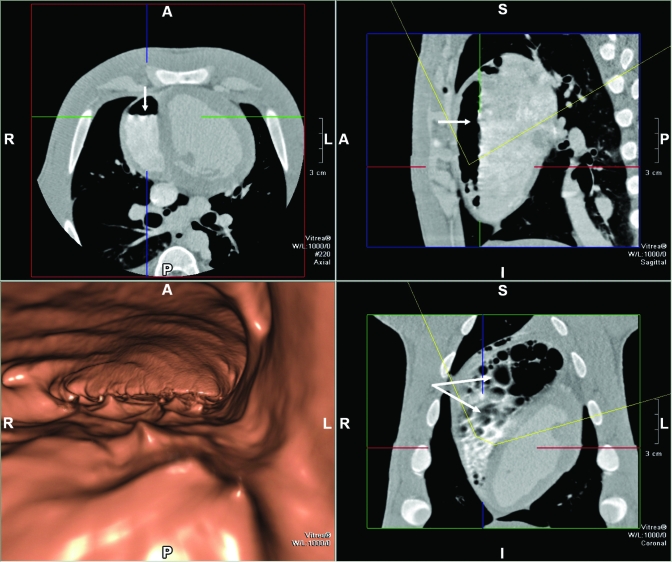
Figure 1 includes axial and 3D volume-rendered views by using fly-through imagery (Vitrea 4.0, Vital Images, Minnetonka, MN) of the accumulated air within the right ventricular. Air is presented as the dark region within the right ventricle, and arrows depict the air–blood interface in the cross-sectional (upper left), sagittal (upper right) and frontal (lower right) views with a slice thickness of 0.5 mm. The animal was in a prone position for the CT scans, and fluid leveling of blood is clearly apparent in cross-sectional and sagittal views. It is noteworthy that by positioning the CT slice at the level of the air–fluid interface (lower right panel), the air–blood interface has an appearance consistent with bubbles or froth (arrows). This finding is consistent with the corrugated appearance of the air–blood interface (arrows) in the axial and sagittal views. The lower left panel depicts a 3D volume-rendered fly-through image at a virtual viewing location within the right ventricle, identified as the intersection of the cursors in the planar views. The viewing orientation and viewing angle are depicted by the yellow arc in these views. This virtual location is approximately 1 cm above the air–blood interface, with the anterior wall of the right ventricle depicted as the cavernous roof and the air–blood interface the cavity floor. The view is oriented from apex to base and depicts the dynamic nature of the air–blood interface not previously demonstrated by CT imaging.
Figure 1.
Fly-through (lower left panel) view and planar images (upper left, upper right, and lower right) of an air embolus within the right ventricle, demonstrating reflected waves at the air–blood interface. Arrows demonstrate fluid-surface features consistent with bubbles within the right ventricle. A, anterior; P, posterior; L, left; R, right; S, superior; I, inferior.
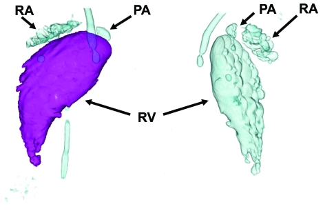
Figure 2 presents post-processed 3D volume-renderings (Aquilion 64 TSX-101A) of accumulated bubbles of air within the right ventricle, right atrium, pulmonary artery, and extracardiac thoracic veins (tubular appearance). These images were rotated to highlight the appearance of the anterior (left) and posterior (right) air chamber surfaces. The 3D volume-rendered images allowed the measurement of air volume within the right ventricle. The volume of air depicted in Figure 2 was 11.5 mL, and total right ventricular volume was 51 mL.
Figure 2.
Two rotated views of air (bubble) accumulation in the right ventricle (RV), right atrium (RA), pulmonary artery (PA), and extracardiac thoracic veins (tubular).
Discussion
Although prior investigators have presented axial views of large volumes of air within nondependent cardiovascular structures,13 the temporal and spatial resolution of current-generation CT scanners permitted us to capture previously unreported CT findings consistent with the classic descriptions of the direct visualization of large venous air emboli and the presence of water-wheel or mill-wheel murmur. These images demonstrate the complexity of air–blood interface dynamics associated with this murmur.
This case report is 1 example of a venous air embolus associated with contrast angiographic procedures. Venous air emboli should be considered immediately with any surgical or nonsurgical procedure or traumatic event in the setting of a pressure gradient for air entry into the venous system9 with the sudden presentation of unexplained hypotension, hypoxemia, and decreased end-tidal CO2. Although risk for venous air emboli was associated historically with a variety of neurosurgical, orthopedic, and obstetrical procedures, it is now appreciated that minimally invasive procedures involving insufflation, the placement and especially removal of central venous access catheters, and pain management procedures may be associated with life-threatening air emboli.9 Discerning investigators and veterinary and technical staff should be aware of the potential of venous air emboli for catastrophic events not only with advanced imaging procedures but also with more common procedures, their varied presentation, and their prevention and treatment.9 In summary, this case report presents the first CT evidence of intracardiac air–blood interface dynamics associated with a classic mill-wheel murmur.
Acknowledgments
The authors thank Ms Suzy M Kai for her assistance with formatting the manuscript and Mr James R Bulgrin for assistance in hemodynamic monitoring. The views expressed in this article are those of the authors and do not reflect the official policy of the Department of Army, the Department of Defense, or the United States Government.
References
- 1.Brechner VL, Bethune RW. 1971. Recent advances in monitoring pulmonary air embolism. Anesth Analg 50:255–261 [PubMed] [Google Scholar]
- 2.Deceuninck O, De Roy L, Moruzi S, Blommaert D. 2007. Images in cardiovascular medicine. Massive air embolism after central venous catheter removal. Circulation 116:e516–e518 [DOI] [PubMed] [Google Scholar]
- 3.Durant TM, Long J, Oppenheimer MJ. 1947. Pulmonary (venous) air embolism. Am Heart J 33:269–281 [DOI] [PubMed] [Google Scholar]
- 4.Groell R, Schaffler GJ, Rienmueller R, Kern R. 1997. Vascular air embolism: location, frequency, and cause in electron-beam CT studies of the chest. Radiology 202:459–462 [DOI] [PubMed] [Google Scholar]
- 5.Husain S, Ahmed L, Al-Sawwaf M. 2006. Venous air embolism from intravenous CT contrast administration. J Am Coll Surg 202:197. [DOI] [PubMed] [Google Scholar]
- 6.Kizer KW, Goodman PC. 1982. Radiographic manifestations of venous air embolism. Radiology 144:35–39 [DOI] [PubMed] [Google Scholar]
- 7.Marchand P, Van Hasselt H, Luntz CH. 1964. Massive venous air embolism. S Afr Med J 38:202–208 [PubMed] [Google Scholar]
- 8.Martland HS. 1945. Air embolism: with special reference to its surgical importance. Am J Surg 68:281–286 [Google Scholar]
- 9.Mirski MA, Lele AV, Fitzsimmons L, Toung TJ. 2007. Diagnosis and treatment of vascular air embolism. Anesthesiology 106:164–177 [DOI] [PubMed] [Google Scholar]
- 10.Muth CM, Shank ES. 2000. Gas embolism. N Engl J Med 342:476–482 [DOI] [PubMed] [Google Scholar]
- 11.Orebaugh SL. 1992. Venous air embolism: clinical and experimental considerations. Crit Care Med 20:1169–1177 [DOI] [PubMed] [Google Scholar]
- 12.Palmon SC, Moore LE, Lundberg J, Toung T. 1997. Venous air embolism: a review. J Clin Anesth 9:251–257 [DOI] [PubMed] [Google Scholar]
- 13.Price DB, Nardi P, Teitcher J. 1987. Venous air embolization as a complication of pressure injection of contrast media: CT findings. J Comput Assist Tomogr 11:294–295 [DOI] [PubMed] [Google Scholar]
- 14.van Hulst RA, Klein J, Lachmann B. 2003. Gas embolism: pathophysiology and treatment. Clin Physiol Funct Imaging 23:237–246 [DOI] [PubMed] [Google Scholar]
- 15.Woodring JH, Fried AM. 1988. Nonfatal venous air embolism after contrast-enhanced CT. Radiology 167:405–407 [DOI] [PubMed] [Google Scholar]


