

Abstract
The surface plasmon-coupled emission microscope provides high sensitivity for surface imaging. However, it suffers from a distorted donut-shape point-spread function (PSF). Here we report an effective yet simple method to correct for the distortion by introducing a spiral phase plate. This modification converts the donut PSF into one that is single lobed, which is preferable for imaging. The optical performance of the system is characterized and compared with previous publications. This technique provides more than twofold lateral resolution enhancement.
The use of surface plasmons in microscopy was proposed as a way to measure small variations on surfaces due to sensitivity of the surface plasmons to small changes in the local dielectric environment [1,2]. This has been successfully applied in biology, for example, to measure the distance of a cell’s membrane from its substrate and for sensitive measurement of protein binding constants [3,4]. For applications where fluorescence detection is desirable, a recent method known as surface-plasmon-coupled emission (SPCE) has been developed, which makes use of surface plasmons to excite fluorophores close to the substrate, with detection of the emission performed on the opposite side of the metal film [5]. This technique has the advantages of improved detection signal-to-noise ratio from better background suppression, reduced excitation volume, and minimized photobleaching by increasing fluorophore radiative decay rate. These advantages allow higher sensitivity fluorescence correlation spectroscopy measurements [6]. SPCE microscopy has also been developed and applied to image and study muscle fibers due to the enhanced detection of fluorescent signal [7,8]. However, it has been shown that the plasmon-assisted fluorescence emission results in a point-spread function (PSF) that has an undesirable donut shape and an FHWM two times worse than the diffraction limit [9]. While numerical deconvolution can be used to mitigate the distortions in the PSF [10], it can suffer from several limitations such as the inadvertent enhancement of noise artifacts. Furthermore, it requires prior measurement of the system PSF, leading to practical difficulties especially in biological experiments. In this Letter, we propose a method to optically correct the distorted PSF of a surface plasmoncoupled emission microscope (SPCEM) by conversion to a single-lobe Airy disklike PSF, which is more desirable for imaging. An analysis of the optical transfer function (OTF) is also presented.
The schematic in Fig. 1 shows the proposed modification to the SPCEM. For simplicity, an inverted total internal reflection fluorescence (TIRF) microscope with a high-NA objective is normally used. In the setup, fluorescent probes on the metal-coated cover slip are excited by surface plasmons, which are excited by the p-polarized plane wave incident at the surface plasmon resonance angle. Fluorescence emission is then collected by the same objective. Along the infinity corrected detection path at a point conjugate to the back focal plane (BFP), we place a single-order spiral phase plate (SPP) to superpose a spiral phase to the emission light prior to CCD imaging. The SPP is an optical element that has a thickness that increases linearly with the azimuthal angle. For an SPP with topological charge of one, its thickness is given by
| (1) |
where d0 is the base thickness of the plate, λ is the emission wavelength, n is the refractive index of the plate, and ϕ denotes the azimuthal angle. The insertion of the SPP thus adds a phase delay of exp(iϕ) to the wavefront of the emission light.
Fig. 1.

(Color online) Setup of modified SPCE microscopy using a high-NA TIRF objective, with an SPP inserted in the infinity-corrected optical path of the detection optics.
The addition of the SPP affects the polarization of the field at the BFP of the objective. Based on the expressions in [9], we calculated the field at the BFP of the objective for a fluorescent molecule whose emission dipole moment is axial, with and without the SPP, and plotted the polarization direction of the field at a time instance t=0 in Fig. 2. The objective NA is assumed to be 1.45, and the spatial frequencies, kx and ky, have been normalized to the free- space wavenumber. In Fig. 2(a) without the SPP, the SPCE emission displays a radial polarization pattern. This causes the field to interfere destructively on-axis when refocused onto the CCD with a low NA imaging lens (which is the objective NA divided by its magnification), resulting in the dip at the center of the PSF. The effect of the SPP on the polarization of the emission is shown in Fig. 2(b). In effect, the SPP introduces a spiral phase that causes polarization vectors within each meridional plane to be in phase and as a result causes the field to interfere constructively at the focus, hence yielding a single-lobe PSF without the dip.
Fig. 2.

Emission at the BFP of the objective at time instance t=0. (a) Polarization pattern of the electric field without the SPP and (b) changes in polarization when the SPP is inserted. The insets show that the intensity at the BFP remain the same.
To understand the effect of the SPP in the frequency domain, we also analyzed the system in terms of the vectorial OTF formalism, which is used in high-aperture imaging in order to take into account depolarization effects caused by the high-NA objective [11]. The two-dimensional (2D) vectorial OTF is given by the 2D Fourier Transform of the intensity PSF,
| (2) |
which is written as a sum of the autocorrelations of the 3D vectorial pupil functions Px, Py, and Pz whose expressions can be obtained in closed forms. The normalized spatial frequency is denoted by l. Figure 3(a) shows the calculated vectorial OTFs. The OTFs are rotationally symmetric and show similar frequency responses for l < 1. However, without the SPP, the OTF of SPCEM becomes negative for some spatial frequencies l > 1. This implies that for these frequencies, there is a phase change of π, which results in a reversal of contrast for those high spatial frequencies [11]. The donut PSF structure of SPCEM and the dip in its center can be attributed to the contrast reversal present for l > 1, where the OTF turns negative. In comparison, the OTF for the imaging system with the SPP remains positive within the whole support of the spatial frequencies and does not have the negative contrast that was evident in the first case.
Fig. 3.

(Color online) (a) Comparison of the vectorial OTF of SPCEM without SPP (solid curve) and with SPP (dashed curve) (b) Characteristics of SPP errors: dip ratio I0 (plus signs) and normalized FWHM (crosses) as a function of misalignment Δw; I0 (circles) and FWHM (diamonds) as a function of wavelength mismatch Δλ/λ.
Since alignment errors will likely be present in any experimental setup, we further investigated the effects misalignment of the SPP has on the PSF. As the system is rotationally invariant, we considered only translational misalignment of the SPP with respect to the back aperture of the objective. We defined two metrics—I0, which measures the ratio of intensity at the origin to the peak PSF intensity as well as FWHM (normalized by the FWHM of a perfectly aligned SPP), and plotted them as a function of misalignment Δw (normalized by the back aperture radius) [see Fig. 3(b)]. In general, translational misalignment breaks the cylindrical symmetry of the PSF, and therefore the worst case FWHM is plotted. Nevertheless, the graph shows relatively good robustness to misalignment up to a value of Δw=0.5, with only a corresponding increase in FWHM of ~12% and a decrease of ~15% in I0. We also plotted the same metrics for the case where the target wavelength of the SPP deviates from the designed wavelength. This can happen, for example, during fabrication due to errors inherent in the fabrication process. Figure 3(b) show that the I0 and FWHM metrics for wavelength mismatch Δλ/λ of ±10% are relatively flat, which indicates strong robustness to errors in the designed SPP wavelength.
In our experimental setup, an inverted TIRF microscope (IX71, Olympus) was used with a high-NA objective (Plan Apo 60X NA1.45) and a 532 nm cw laser source. A transmission SPP with a designed wavelength of 560 nm was inserted in the detection path before the imaging lens. The SPP consists of a vortex microstructure patterned on a poly(methyl methacrylate) layer that was spin-coated on a glass substrate (RPC Photonics). It has transmission efficiency greater than 80% and a wavelength design error less than 10%. Fluorescent beads (F8792, Molecular Probes) with a nominal diameter of 40 nm was placed on a Au-SiOx (40 and 5 nm, respectively) coated cover slip and imaged with a CCD (Retiga EXi, QImaging). SPCEM PSFs with and without the SPP are shown in Fig. 4. In general, the experimental results show good agreement with the theoretical predictions. The morphologies of the experimental PSFs look similar to the theoretical PSFs. Furthermore, the simulations show a decrease in the FWHM from 437 nm to 193 nm, while the experiments show a corresponding decrease from 456 nm to 217 nm, translating into a 2.1 times improvement in resolution. The difference between theoretical and experimental FWHMs is attributed to the fluorescent beads being finite in size.
Fig. 4.
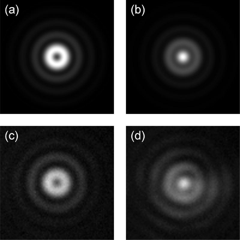
Comparison between simulation and experimental results. Simulated PSF (a) without SPP and (b) with SPP; experimental PSF (c) without SPP and (d) with SPP. Image scale is 2 μm × 2 μm.
In conclusion, in any imaging system, it is important to ensure that the imaging PSF has a proper form. To our knowledge, this is the first demonstration of optical conversion of the donut PSF into one that is single lobe with the use of a spiral phase plate. The resolution is shown to improve by a factor of 2 as a result. In general, the SPP is also robust to misalignment as well as wavelength mismatch. It is envisaged that this technique will be beneficial to the application of SPCE imaging without requiring the use of imprecise numerical restoration techniques. This technique may also be used to improve detection efficiency in confocal reflection and fluorescence microscopy, which makes use of radially polarized illumination [12,13].
Supplementary Material
Acknowledgments
This research was funded by the Singapore-MIT Alliance (SMA).
Footnotes
OCIS codes: 240.6680, 180.2520, 180.0180.
References
- 1.Yeatman E, Ash E. Electron Lett. 1987;23:1091. [Google Scholar]
- 2.Rothenhäusler B, Knoll W. Nature. 1988;332:615. [Google Scholar]
- 3.Giebel KF, Bechinger C, Herminghaus S, Riedel M, Leiderer P, Weiland U, Bastmeyer M. Biophys J. 1999;76:509. doi: 10.1016/s0006-3495(99)77219-x. [DOI] [PMC free article] [PubMed] [Google Scholar]
- 4.Liedberg B, Nylander C, Lundstrom I. Sens Actuators. 1983;4:299. [Google Scholar]
- 5.Lakowicz J, Malicka J, Gryczynski I, Gryczynski Z. Biochem Biophys Res Commun. 2003;307:435. doi: 10.1016/S0006-291X(03)01214-2. [DOI] [PMC free article] [PubMed] [Google Scholar]
- 6.Borejdo J, Calander N, Gryczynski Z, Gryczynski I. Opt Express. 2006;14:7878. doi: 10.1364/oe.14.007878. [DOI] [PubMed] [Google Scholar]
- 7.Burghardt TP, Charlesworth JE, Halstead MF, Tarara JE, Ajtai K. Biophys J. 2006;90:4662. doi: 10.1529/biophysj.105.079442. [DOI] [PMC free article] [PubMed] [Google Scholar]
- 8.Borejdo J, Gryczynski Z, Calander N, Muthu P, Gryczynski I. Biophys J. 2006;91:2626. doi: 10.1529/biophysj.106.088369. [DOI] [PMC free article] [PubMed] [Google Scholar]
- 9.Tang WT, Chung E, Kim YH, So PTC, Sheppard CJR. Opt Express. 2007;15:4634. doi: 10.1364/oe.15.004634. [DOI] [PubMed] [Google Scholar]
- 10.Chung E, Kim YH, Tang WT, Sheppard CJR, So PTC. Opt Lett. 2009;34:2366. doi: 10.1364/ol.34.002366. [DOI] [PMC free article] [PubMed] [Google Scholar]
- 11.Sheppard CJR, Larkin KG. Optik. 1997;107:79. [Google Scholar]
- 12.Biss DP, Youngworth KS, Brown T. Appl Opt. 2006;45:470. doi: 10.1364/ao.45.000470. [DOI] [PubMed] [Google Scholar]
- 13.Tang WT, Yew Elijah YS, Sheppard CJR. Opt Lett. 2009;34:2147. doi: 10.1364/OL.34.002147. [DOI] [PubMed] [Google Scholar]
Associated Data
This section collects any data citations, data availability statements, or supplementary materials included in this article.