Abstract
Purpose
The objective of this study was to evaluate the in vivo knee kinematics to assess the available functional motion of the characteristic mobile-bearing prosthesis design and to examine whether the artificial joint would work in vivo according to its design concept.
Methods
We studied 14 knees (11 patients) implanted with the Vanguard RP Hi-Flex prosthesis. This prosthesis has a highly original form of post-cam called a PS saddle design with high compatibility, and with a rotating plate mobile-bearing mechanism. The cylinder-type post-cam is designed to enable contact in early flexion ranges, and to prevent paradoxical anterior femoral component movement. Each patient performed weight-bearing deep knee bending under fluoroscopic surveillance. Motion between each component including the polyethylene insert was analyzed using the 2D/3D registration technique.
Results
The mean range of motion was 122.0°. The mean femoral component rotation for the tibial tray was 5.0°. No paradoxical anterior movement of the nearest point was confirmed between the femoral component and the tibial tray in the early flexion ranges. Initial contact of the post-cam was confirmed at a knee flexion angle of 33.8°. Subsequently, the wide contact of the post-cam was maintained until flexion reached 120° in all knees, but disengagement of the post-cam was observed in two knees when flexion was ≥130°.
Conclusions
The results of this study demonstrated that the prosthesis design generally works in vivo as intended by its design concept. The present kinematic data may provide useful information for improvement of high-flex type prostheses.
Introduction
Total knee arthroplasty (TKA) procedures require high functionality and durability and deep knee flexion is considered to be especially important as an indicator of higher function [1]. Many high-flex type prostheses have been developed to enable deep knee flexion. However, instability and loosening may occur when deep knee flexion becomes excessive [2]; therefore, it is extremely difficult to achieve these objectives simultaneously.
The mobile-bearing TKA, developed in the 1970s, was expected to reduce shear forces on the tibial tray by achieving tolerability of rotation in the insert and the tibial tray, while decreasing shear stress on the insert by increasing conformity between the femoral component and the insert and widening the contact area. Although favorable long-term outcomes have been reported [3–5], it has been suggested that clinical symptoms (range of motion and pain relief) and long-term outcomes do not differ when compared with the conventional fixed-type TKA [6–9]. In addition, the mobile bearing TKA did not display more favorable outcomes in regards to dislocation of the mobile insert, which is a complication specific to the mobile-bearing TKA [10, 11]. Abrasion of the undersurface of the insert has also been reported to occur with the mobile bearing TKA [12].
Further improvement of the mobile mechanism and post-cam design is required to achieve deep knee flexion and favorable long-term outcomes with the mobile-bearing TKA. Therefore, it is important to understand the in vivo TKA kinematics in the deep flexion range for those patients who have implanted mobile bearing devices.
In vivo motion analyses of various prostheses have been conducted in recent years, further elucidating the kinematics between metal components upon weight-bearing motion [13–18]. It has also become possible to analyze the polyethylene inserts of mobile-bearing prostheses by interpolating tantalum beads into the insert [19–21].
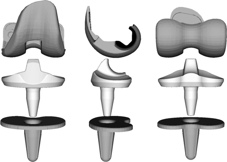
The Vanguard RP Hi-Flex prosthesis (Biomet Europe, Bridgend, UK) used in this analysis has a highly original post-cam form called a PS saddle design with high compatibility and with a rotating plate mobile-bearing mechanism (Fig. 1). Furthermore, this prosthesis increases the conformity between the femoral component and the insert with its function as a smooth third articular surface continuing within the intercondylar area. In addition, the cylinder-type post-cam enables contact in the early phase of flexion and prevents paradoxical anterior movement of the femoral component. However, it has not been clearly determined whether the mechanism of such a post-cam in the original form could be reproduced in vivo. We hypothesized that this characteristic prosthesis design would affect knee kinematics. This study aimed to evaluate the in vivo knee kinematics to identify the available functional motion of the characteristic mobile-bearing prosthesis design, and examine whether the artificial joint would work in vivo according to its design concept.
Fig. 1.
Vanguard RP Hi-Flex (Biomet Europe, Bridgend, UK) is a prosthesis with a highly original form of post-cam called a PS saddle design with high compatibility, and with a rotating plate mobile-bearing mechanism
Methods
Twenty-three knees from 17 patients received the mobile-bearing TKA using the Vanguard RP Hi-Flex from July 2008 to August 2009. Fourteen knees from 11 patients who could clinically achieve knee flexion of 120° or more and who scored 90 points or higher on the Knee Society score were examined in this analysis. All patients gave informed consent and this project was approved by our institutional review board. All patients were diagnosed with medial osteoarthritis knees. The mean patient age was 71.6±8.1 years (range, 61–82) at the time of surgery, and the mean postoperative follow-up period was 4.9±2.2 months (range, 3.3–7.5) at the time of the fluoroscopic examination, and radiolucent lines were not found in any patient. Patient demographics are listed in Table 1.
Table 1.
Patient demographics
| Parameter | Mean | Range |
|---|---|---|
| Weight (kg) | 58.5 | 42–72 |
| Height (cm) | 150.1 | 141–466 |
| Body mass index (kg/m2) | 25.7 | 18.3–31.2 |
| Pre-operative passive ROM (°) | 103.2 | 75–125 |
| Pre-operative FTA (°) | 181.8 | 175–186 |
| Post-operative passive ROM (°) | 127.7 | 120–130 |
| Post-operative FTA (°) | 174.0 | 171–177 |
| α angle (°) | 96.1 | 94.8–99.0 |
| β angle (°) | 89.8 | 87.2–90.9 |
| γ angle (°) | 3.5 | 1.0–6.2 |
| θ angle (°) | 85.7 | 83.3–88.5 |
ROM range of motion, FTA femorotibial angle
One senior surgeon (MF) performed all surgeries, using a mini-parapatellar approach. The femoral component was placed with the surgical epicondylar axes used as an indicator of rotation, while the tibial tray was placed with the priority on bone coverage. As shown previously, five tantalum beads were injected into the insert at known positions using a template and a RSA injector during the surgery [20].
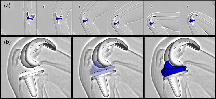
Fluoroscopic images of the weight-bearing knee motion, bending from the extended position to the flexed position, were taken from a lateral view. The data were recorded using a digital X-ray system (1,024 × 1,024 × 12 bit/pixel, 7.5-Hz serial spot images as a DICOM file) with a 17-inch flat panel detector system (C-vision Safire; Shimadzu, Kyoto, Japan). Individual component spatial positioning was estimated using the 2D/3D registration technique [22, 23] (Fig. 2a). This technique is based on a contour-based registration algorithm using single-view fluoroscopic images and 3D computer-aided design models. Estimation accuracy of the relative motion between metal components was ≤0.5° in rotation and ≤0.4 mm in translation. Registration of the polyethylene insert was determined using a three-dimensional model of the insert containing five tantalum beads positioned just before insertion during the surgery (Fig. 2b).
Fig. 2.
a 2D/3D registration technique uses computer-assisted design models to reproduce the spatial position of femoral and tibial components from single-view fluoroscopic images. b Rotation of the insert was determined using a 3D model of the insert containing five tantalum beads positioned just before insertion during the operation
The flexion angle between the femoral component and the tibial tray, the amount of axial rotation between the femoral component and the tibial tray, and the absolute value for axial rotation of the femoral component for the insert were measured as the end points. The origin was defined as the center of gravity for the component in the femoral coordinate system. The origin in the tibial coordinate system was defined as the centre of the tibial tray surface. The origin of the insert coordinate system was defined as the centre of the insert undersurface. Knee rotations were described using the joint rotational convention of Grood and Suntay [24]. External rotation of the femoral component for the tibial tray was denoted as positive. In addition, anteroposterior translation of the nearest points between the femoral component and the tibial tray, and between the femoral component and the insert, were measured individually to evaluate the kinematic patterns. The nearest point was determined as the centre of quasi-contact by calculating the closest distance between the surfaces on computer-aided design models for each of the medial and lateral sides. Furthermore, the flexion angle, at which contact with the post-cam was observed, was measured. The nearest distance between the cam of the femoral component and the post of the insert was measured to confirm that the contact with the post-cam would be ≤0.5 mm [18]. Since it was a cylinder-type post-cam, we also measured the flexion angle at which the cam was in contact with the top of the post.
Statistical analysis
All data are expressed as mean ± standard deviation. Parametric non-paired Student’s t-tests were used for comparisons between anteroposterior translation of the nearest points on the medial and lateral sides. Values of P < 0.05 were considered statistically significant.
Results
Range of motion
The mean maximum extension angle between the femoral component and the tibial tray was 1.6±5.6° (range, −11.6 to 8.1). The mean maximum flexion angle was 120.5±8.6° (range, 105.3–137.7). The mean range of motion was 122.0±10.2° (range, 104.9–140.0).
Axial rotation
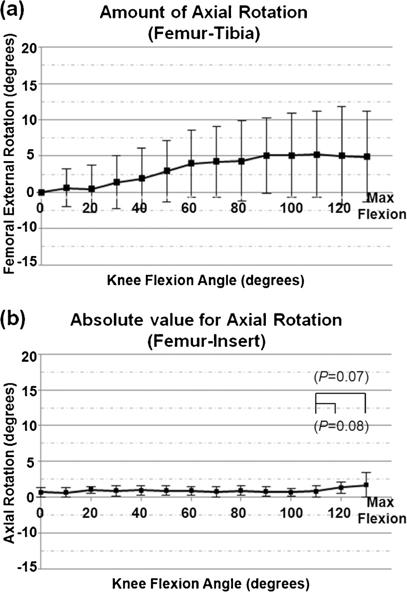
The femoral component was rotated externally to the tibial tray for 5.1±5.2° (range, −4.7 to 12.6) on average along with flexion until flexion reached 90°. Subsequently, almost no external rotation was identified until the maximum flexion was observed, and the external rotation was ≤0.5° from the 90° knee flexion angle to the maximum flexion (Fig. 3a). The femoral component was rotated externally to the tibial tray from the extension position to the maximum flexed position along with flexion in 12 out of 14 knees. The femoral component was rotated internally to the tibial tray along with flexion in two of 14 knees.
Fig. 3.
a Amount of femoral component axial rotation for the tibial tray from maximum extension to maximum flexion. The horizontal scale shows the flexion angle between the component, and the vertical scale shows the amount of axial rotation. Positive values represent external rotation. b Absolute value for axial rotation of the femoral component for the insert. The mean absolute value beyond flexion of 120° tended to be larger than that at flexion of 110°
Almost no rotation mismatch was observed between the femoral component and the insert until flexion reached 110°, and the mean absolute value for axial rotation was 0.8±0.7° (range, 0.1–1.7) at knee flexion of 110° (Fig. 3b). The mean absolute value beyond flexion of 120° tended to be larger than that at flexion of 110°, and the mean absolute value was 1.8 ± 1.7° (range, 0.2–5.8°) at the maximum flexion (P = 0.07). However, this difference was not significant.
AP translation
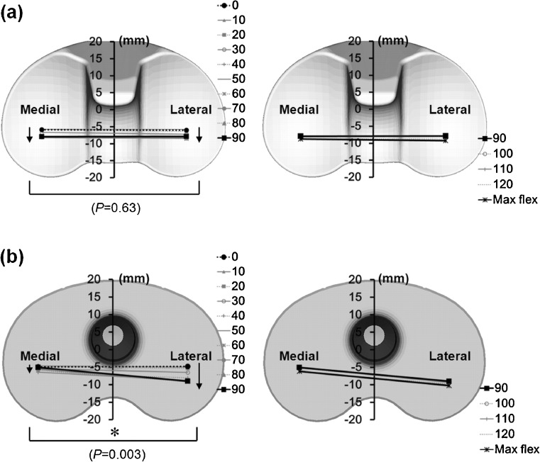
The nearest points between the femoral component and the insert on the medial and lateral sides were moved posteriorly by a mean of 2.1±1.7 mm (range, 0.1–5.1) and 1.8±1.5 mm (range, −0.4 to 4.5), respectively, until flexion reached 90°. No significant difference was confirmed between the movement on the medial and lateral sides (P = 0.63). Virtually no movement of the nearest point was confirmed from the 90° knee flexion angle to the maximum flexion (Fig. 4a).
Fig. 4.
a Anteroposterior translation of the bilateral nearest point between the femoral component and the insert. b Anteroposterior translation of the bilateral nearest point between the femoral component and the tibial tray. The difference was significant in AP translation between medial and lateral (*P = 0.003)
The nearest point between the femoral component and the tibial tray moved posteriorly on the lateral side for a mean of 3.9±2.9 mm (range, −1.2 to 8.5) along with flexion until flexion reached 90°. Almost no movement was observed from the 90° knee flexion angle to the maximum flexion. Virtually no posterior and anterior movements were confirmed in all flexion ranges, and the movement was 2 mm or less on the medial side (Fig. 4b).
The pivot pattern of the femoral component to the tibial tray was observed until flexion reached 90°. As this occurred, the medial pivot pattern was observed because movement of the nearest point on the lateral side was significantly larger than that on the medial side (P = 0.003), and no posterior movement of the nearest point was found in the deep flexion range on either side.
Post-cam engagement
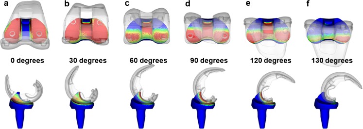
Initial contact of the post-cam was confirmed at a knee flexion angle of 33.8±4.5° (range, 28.2–43.4). Subsequently, wide contact of the post-cam was maintained until flexion of 120° in all cases, but disengagement of the post-cam was observed in two knees when flexion was ≥130° (Fig. 5).
Fig. 5.
a–f Dynamic deep knee flexion was shown under weight-bearing conditions. The red area denoted a quasi-contact area that was defined by the closest distances between the cam of the femoral component and the post of the insert. b In this patient, initial contact of the post-cam was confirmed at flexion of 30°. f The post-cam disengagement was observed at flexion of 130°
Discussion
This study presented detailed in vivo kinematics of the characteristic design of the mobile-bearing prosthesis including the polyethylene insert. We revealed that this characteristic design considerably affected knee kinematics. Postoperative kinematics can be affected by various factors, such as the form and setting of the artificial joint face, muscle force and soft tissue balance. We believe that the kinematics of the mobile-bearing TKA would also be affected by the mobile-bearing mechanism of the rotating plate form type, in which the rotation center of the insert was located at the center of the tibial tray [20].
The femoral component rotates externally in line with the external rotation of the insert as the centre of rotation in the rotating plate type of prosthesis if there is no axial rotation mismatch or posterior movement of the nearest point between the femoral component and the insert. Therefore, a central pivot is observed, in which the nearest points between the femoral component and the tibial tray on the medial and lateral sides are moved anteriorly and posteriorly, respectively.
Furthermore, since no mismatch of axial rotation was confirmed between the femoral component and the insert in this study, the nearest points on the medial and lateral sides tended to move anterior and posterior in line with external rotation of the insert, respectively. The present results demonstrated that post-cam engagement occurred at approximately 30° of knee flexion. External rotation of the femoral component and posterior movement of the nearest point between the femoral component and the insert occurred simultaneously after post-cam engagement. Consequently, the nearest point on the medial side did not move anteriorly, which induced a medial pivot motion until flexion reached 90°.
The results regarding the knee flexion angle were similar to prior reports of the mobile-bearing TKA; however, the rotation of the femoral component for the tibial tray tended to be smaller than previously reported [20]. Shiramizu et al. conducted an in vitro comparison of six devices, and reported that the contact area between the femoral component and the insert achieved by the Vanguard RP Hi-Flex, also used in our analysis, was larger than that achieved by other devices at individual flexion angles from 0° to 110° [25]. The large contact area and high conformity likely result in insufficient flexibility between the femoral component and the insert. The rotating plate mechanism was designed to allow rotation on one flat surface on the tibial tray, but the postoperative knee may be affected by posterior inclination, varus-valgus placement and weight-bearing. Under such in vivo circumstances, it may be difficult to enable complicated motion with six types of flexibility, such as knee joint flexion on one flat surface.
Initial contact of the post-cam was confirmed at 33.8° of knee flexion, and the design to enable the post-cam to work in an early phase of flexion was reproduced in vivo. Wide contact was maintained until flexion of 120° was reached in all cases. However, disengagement of the post-cam was observed in two knees when knee flexion was ≥130°. Moynihan et al. also suggested that disengagement of the post-cam occurred in deep flexion ranges, showing that disengagement might be affected by soft tissue tension, such as from the posterior articular capsule [17]. Furthermore, the absolute value for axial rotation of the femoral component for the insert beyond flexion of 120° tended to be larger than that at 110° of flexion in this analysis. One possible explanation is that the cylinder-type post-cam with high conformity might have difficulty functioning under the influence of soft tissue tension or thigh-calf impingement in deep flexion ranges. However, no paradoxical anterior movement of the nearest point was confirmed between the femoral component and the tibial tray in early flexion ranges; therefore, we considered that the form of the post-cam cylinder-type would be effective until knee flexion of 120° was reached.
The kinematics of the medial pivot pattern would be close to that of a normal knee up to 90° of knee flexion, and thus it may be useful to improve compatibility of the patellofemoral joint, and to prevent pain caused by soft tissue tension. However, it is unclear whether reproduction of normal knee kinematics would improve clinical outcomes. Additionally, it will be necessary in the future to discuss both the results of kinetic analysis such as contact stress and long-term clinical outcome.
There are some limitations to the present study. One limitation was the small sample size and selection bias. However, even with a small size sample, the TKA kinematics analysis identified differences among the various prostheses. Similar reports have analyzed nine–20 knees [13–21]. Additionally, the component positions and rotations for the femoral and tibial bones were not considered. As we used a mobile-bearing prosthesis in this analysis, we set the tibial tray with a priority on bone coverage in anticipation of prosthesis self-alignment. Therefore, the positional relation between the femoral component and the tibial tray was more affected by setting of the tibial tray, compared with the fixed-type prosthesis. Future studies should include kinematic analysis of the entire knee, including the bones, in consideration of such settings.
In conclusion, this study presented detailed in vivo kinematics for the Vanguard RP Hi-Flex prosthesis. This characteristic prosthetic design generally works in vivo according to its design concept. No paradoxical anterior movement of the nearest point was confirmed between the femoral component and the tibial tray in the early flexion ranges. Wide contact of the post-cam was maintained until flexion reached 120°, but disengagement of the post-cam was observed in two knees when flexion was ≥130°. The current kinematic data may provide useful information for improvement of high-flex type prostheses.
References
- 1.Argenson JN, Parratte S, Ashour A, Komistek RD, Scuderi GR. Patient-reported outcome correlates with knee function after a single-design mobile-bearing TKA. Clin Orthop Relat Res. 2008;466:2669–2676. doi: 10.1007/s11999-008-0418-x. [DOI] [PMC free article] [PubMed] [Google Scholar]
- 2.Han HS, Kang SB, Yoon KS. High incidence of loosening of the femoral component in legacy posterior stabilised-flex total knee replacement. J Bone Joint Surg Br. 2007;89:1457–1461. doi: 10.1302/0301-620X.89B11.19840. [DOI] [PubMed] [Google Scholar]
- 3.Buechel FF., Sr Long-term followup after mobile-bearing total knee replacement. Clin Orthop Relat Res. 2002;404:40–50. doi: 10.1097/00003086-200211000-00008. [DOI] [PubMed] [Google Scholar]
- 4.Sorrells RB, Voorhorst PE, Murphy JA, Bauschka MP, Greenwald AS. Uncemented rotating-platform total knee replacement: a five to twelve-year follow-up study. J Bone Joint Surg Am. 2004;86:2156–2162. [PubMed] [Google Scholar]
- 5.Jordan LR, Olivo JL, Voorhorst PE. Survivorship analysis of cementless meniscal bearing total knee arthroplasty. Clin Orthop Relat Res. 1997;338:119–123. doi: 10.1097/00003086-199705000-00018. [DOI] [PubMed] [Google Scholar]
- 6.Mahoney OM, Kinsey TL, D’Errico TJ, Shen J. No functional advantage of a mobile bearing posterior stabilized TKA. Clin Orthop Relat Res. 2012;470:33–44. doi: 10.1007/s11999-011-2114-5. [DOI] [PMC free article] [PubMed] [Google Scholar]
- 7.Lädermann A, Lübbeke A, Stern R, Riand N, Fritschy D. Fixed-bearing versus mobile-bearing total knee arthroplasty: a prospective randomised, clinical and radiological study with mid-term results at 7 years. Knee. 2008;15:206–210. doi: 10.1016/j.knee.2008.01.010. [DOI] [PubMed] [Google Scholar]
- 8.Matsuda S, Mizu-uchi H, Fukagawa S, Miura H, Okazaki K, Matsuda H, Iwamoto Y. Mobile-bearing prosthesis did not improve mid-term clinical results of total knee arthroplasty. Knee Surg Sports Traumatol Arthrosc. 2010;18:1311–1316. doi: 10.1007/s00167-010-1143-z. [DOI] [PubMed] [Google Scholar]
- 9.Watanabe T, Tomita T, Fujii M, Hashimoto J, Sugamoto K, Yoshikawa H. Comparison between mobile-bearing and fixed-bearing knees in bilateral total knee replacements. Int Orthop. 2005;29:179–181. doi: 10.1007/s00264-005-0646-6. [DOI] [PMC free article] [PubMed] [Google Scholar]
- 10.Bhan S, Malhotra R, Kiran EK, Shukla S, Bijjawara M. A comparison of fixed-bearing and mobile-bearing total knee arthroplasty at a minimum follow-up of 4.5 years. J Bone Joint Surg Am. 2005;87:2290–2296. doi: 10.2106/JBJS.D.02221. [DOI] [PubMed] [Google Scholar]
- 11.Hasegawa M, Sudo A, Fukuda A, Uchida A. Dislocation of posterior-stabilized mobile-bearing knee prosthesis. A case report. Knee. 2006;13:478–1482. doi: 10.1016/j.knee.2006.07.002. [DOI] [PubMed] [Google Scholar]
- 12.Lu YC, Huang CH, Chang TK, Ho FY, Cheng CK, Huang CH. Wear-pattern analysis in retrieved tibial inserts of mobile-bearing and fixed-bearing total knee prostheses. J Bone Joint Surg Br. 2010;92:500–507. doi: 10.2106/JBJS.I.00833. [DOI] [PubMed] [Google Scholar]
- 13.Banks S, Bellemans J, Nozaki H, Whiteside LA, Harman M, Hodge WA. Knee motions during maximum flexion in fixed and mobile-bearing arthroplasties. Clin Orthop Relat Res. 2008;410:131–138. doi: 10.1097/01.blo.0000063121.39522.19. [DOI] [PubMed] [Google Scholar]
- 14.Watanabe T, Yamazaki T, Sugamoto K, Tomita T, Hashimoto H, Maeda D, Tamura S, Ochi T, Yoshikawa H. In vivo kinematics of mobile-bearing knee arthroplasty in deep knee bending motion. J Orthop Res. 2004;22:1044–1049. doi: 10.1016/j.orthres.2003.12.013. [DOI] [PubMed] [Google Scholar]
- 15.Tamaki M, Tomita T, Yamazaki T, Hozack WJ, Yoshikawa H, Sugamoto K. In vivo kinematic analysis of a high-flexion posterior stabilized fixed-bearing knee prosthesis in deep knee-bending motion. J Arthroplasty. 2008;23:879–885. doi: 10.1016/j.arth.2008.04.009. [DOI] [PubMed] [Google Scholar]
- 16.Tamaki M, Tomita T, Watanabe T, Yamazaki T, Yoshikawa H, Sugamoto K. In vivo kinematic analysis of a high-flexion, posterior-stabilized, mobile-bearing knee prosthesis in deep knee bending motion. J Arthroplasty. 2009;24:972–978. doi: 10.1016/j.arth.2008.06.012. [DOI] [PubMed] [Google Scholar]
- 17.Moynihan AL, Varadarajan KM, Hanson GR, Park SE, Nha KW, Suggs JF, Johnson T, Li G. In vivo knee kinematics during high flexion after a posterior-substituting total knee arthroplasty. Int Orthop. 2010;34:497–503. doi: 10.1007/s00264-009-0777-2. [DOI] [PMC free article] [PubMed] [Google Scholar]
- 18.Shimizu N, Tomita T, Yamazaki T, Yoshikawa H, Sugamoto K. The effect of weight-bearing condition on kinematics of a high-flexion, posterior-stabilized knee prosthesis. J Arthroplasty. 2011;26:1031–1037. doi: 10.1016/j.arth.2011.01.008. [DOI] [PubMed] [Google Scholar]
- 19.Komistek RD, Dennis DA, Mahfouz MR, Walker S, Outten J. In vivo polyethylene bearing mobility is maintained in posterior stabilized total knee arthroplasty. Clin Orthop Relat Res. 2004;428:207–213. doi: 10.1097/01.blo.0000147135.60185.39. [DOI] [PubMed] [Google Scholar]
- 20.Futai K, Tomita T, Yamazaki T, Tamaki M, Yoshikawa H, Sugamoto K. In vivo kinematics of mobile-bearing total knee arthroplasty during deep knee bending under weight-bearing conditions. Knee Surg Sports Traumatol Arthrosc. 2011;19:914–920. doi: 10.1007/s00167-010-1262-6. [DOI] [PubMed] [Google Scholar]
- 21.Tanaka A, Nakamura E, Okamoto N, Banks SA, Mizuta H. Three-dimensional kinematics during deep-flexion kneeling in mobile-bearing total knee arthroplasty. Knee. 2011;18:412–416. doi: 10.1016/j.knee.2010.08.006. [DOI] [PubMed] [Google Scholar]
- 22.Yamazaki T, Watanabe T, Nakajima Y, Sugamoto K, Tomita T, Yoshikawa H, Tamura S. Improvement of depth position in 2-D/3-D registration of knee implants using single-plane fluoroscopy. IEEE Trans Med Imaging. 2004;23:602–612. doi: 10.1109/TMI.2004.826051. [DOI] [PubMed] [Google Scholar]
- 23.Yamazaki T, Watanabe T, Nakajima Y, Sugamoto K, Tomita T, Maeda D, Sahara W, Yoshikawa H, Tamura S. Visualization of femorotibial contact in total knee arthroplasty using X-ray fluoroscopy. Eur J Radiol. 2005;53:84–89. doi: 10.1016/j.ejrad.2003.09.018. [DOI] [PubMed] [Google Scholar]
- 24.Grood ES, Suntay WJ. A joint coordinate system for the clinical description of three-dimensional motions: application to the knee. J Biomech Eng. 1983;105:136–144. doi: 10.1115/1.3138397. [DOI] [PubMed] [Google Scholar]
- 25.Shiramizu K, Vizesi F, Bruce W, Herrmann S, Walsh WR. Tibiofemoral contact areas and pressures in six high flexion knees. Int Orthop. 2009;33:403–406. doi: 10.1007/s00264-007-0478-7. [DOI] [PMC free article] [PubMed] [Google Scholar]


