

Abstract
Electron microscopy provides an efficient method for rapidly assessing whether a solution of macromolecules is homogeneous and monodisperse. If the macromolecules can be induced to form two-dimensional crystals that are a single layer in thickness, then electron crystallography of frozen-hydrated crystals has the potential of achieving three-dimensional density maps at sub-nanometer or even atomic resolution. Here we describe the lipid monolayer and sparse matrix screening methods for growing two-dimensional crystals and present successful applications to soluble macromolecular complexes: carboxysome shell proteins and HIV CA, respectively. Since it is common to express recombinant proteins with poly-His tags for purification by metal affinity chromatography, the monolayer technique using bulk lipids doped with Ni2+ lipids has the potential for broad application. Likewise, the sparse matrix method uses screening conditions for three-dimensional crystallization and is therefore of broad applicability.
Keywords: Lipid monolayers, Sparse matrix, Two-dimensional crystallization, Electron crystallography, Carboxysome proteins, Retroviral CA proteins
1. Introduction
As in any crystallization trial, one must refine the conditions for crystallization and specimen handling to maximize resolution (1). In general the variables to be tested to achieve two-dimensional (2D) crystallization are similar to those used for three-dimensional (3D) crystallization and include evaluation of divalent cations, pH, detergents, lipids, buffers, ionic strength, temperature, precipitants, ligands, and inhibitors. Purity and yield of the protein are maximized, and proteolysis is minimized. For membrane proteins in detergent micelles, 2D crystals are typically grown by reconstitution methods involving dialysis and/or the use of detergent binding agents (reviewed by Yeager et al., 1999 (2)). Here we will describe two methods for growing 2D crystals of soluble proteins and macromolecular complexes—lipid monolayer and sparse matrix screening. In all cases, the progress of 2D crystallization is assessed by negative-stain electron microscopy (reviewed by Adair and Yeager, 2007 (3)).
In the lipid monolayer crystallization technique (4–6), lipids are spread at an air–water interface so that the aliphatic chains extend into the air, and the lipid headgroups are exposed at the aqueous interface (Fig. 1). Soluble protein molecules present in the aqueous phase bind to the lipid headgroups via electrostatic interactions or by a specific affinity tag. Negatively charged lipids include stearic and oleic acid. DOPS and octadecylamine are positively charged. Affinity tags can exploit a receptor–ligand or enzyme–substrate interaction, such as cholera toxin binding to its receptor (7) and avidin binding to a biotinylated lipid (8). An interaction of general utility exploits the strategy of using recombinant His-tagged proteins (9, 10). The lipid monolayer can be doped with a synthetic lipid containing a chelating nickel head-group that will bind to a protein having a polyhistidine tag. This method would also be applicable for the 2D crystallization of soluble ectodomains of membrane proteins generated by recombinant DNA technology or by release from the membrane by proteolysis. This method can also be used for membrane proteins solubilized in detergent micelles if the detergent is sufficiently mild so that the lipid monolayer is not perturbed. In those instances where the monolayer is disrupted by the detergent, the monolayer can be stabilized by the use of fluorinated lipids (11). In our laboratory, we have used the lipid monolayer technique for growing 2D crystals of a variety of His-tagged proteins: Fab fragments (2), the murine leukemia virus CA protein (12), and carboxysome shell proteins (13).
Fig. 1.
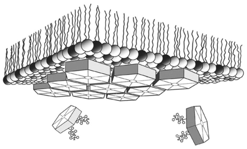
Schematic depiction of 2D lipid monolayer crystallization. Carboxysome BMC shell protein hexamers were localized at the lipid-aqueous interface of a mixed lipid layer with 4:1 (wt:wt) l-α-phosphatidylcholine (light spheres) plus DOGS-NTA-Ni2+ (dark spheres) by means of polyhistidine tag chelation via Ni2+ bound within the polar lipid layer. Resulting 2D crystals were transferred to an EM grid and stained for image diffraction analysis (From ref. (13)).
Carboxysomes are bacterial organelles that form microcompartments for performing enzymatic reactions. The polyhedral shells of carboxysomes (Fig. 2a) are formed by a single layer of CcmK proteins. The lipid monolayer crystallization method was used to grow 2D hexagonal crystals of CcmK proteins (Fig. 2b,c) that mimic the hexagonal lattice within a facet of the polyhedral shell. An aliquot of the protein (10 μl at a protein concentration of 0.5–1.0 mg/ml) was overlaid with 1 μl of a 1:1 chloroform/hexane solution containing 50 mg/ml L-α-phosphatidylcholine doped with 12.5 mg/ml nickel-charged lipid (DOGS-NTA Ni2+), and the crystals grew in 4 h at room temperature. The diffraction pattern of the crystals (Fig. 2d) could be indexed with p1 unit cell parameters that were nearly hexagonal and in close agreement with the center-to-center spacings in the X-ray structures of CcmK proteins. 2D and 3D maps of CcmK proteins (Fig. 3), derived by electron crystallography and tilt reconstruction of the hexagonal crystals, revealed that the packing of the CcmK proteins recapitulated the packing within the planar facets of the polyhedral carboxysome shells.
Fig. 2.
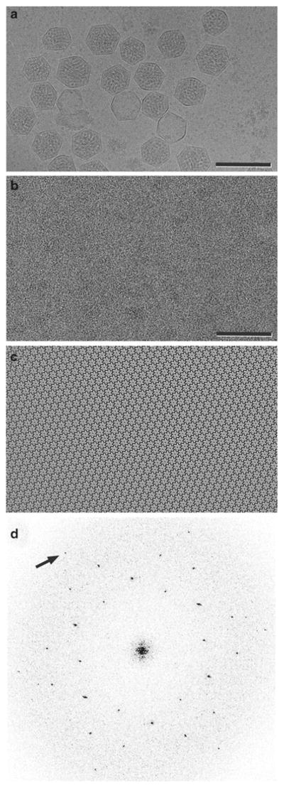
(a) Electron cryomicrograph of carboxysomes, which are bacterial microcompartments formed by CcmK proteins that assemble as polyhedral shells containing key metabolic enzymes. Scale bar = 2,000 Å. (b) Image of negatively stained CcmK1 2D crystals. Scale bar = 500 Å. (c) The underlying order is observed when the image is Fourier filtered, and corrections are made for lattice distortions. (d) The Fourier transform of the negatively stained image displays hexagonal symmetry. The arrow identifies the (2,2) reflection at 17-Å resolution. Images were contrast stretched to emphasize salient features (From ref. (13)).
Fig. 3.

(a ) Projection maps from 2D crystals of three CcmK proteins (white contours) shown projected onto the molecular packings visualized in 3D crystals. In the case of CcmK4, hexamers in 3D crystals packed into uniformly ordered strips (illustrated) but not uniformly oriented layers. (b ) 3D density map (tilted by 15 ° to enhance depth) showing the hexamer packing of CcmK1 in 2D lipid monolayer crystals (gray surface), which recapitulates the packing in the ab lattice plane in 3D crystals (blue ribbon) (pdb id. 3dn9). Center-to-center hexamer spacing is ~68 Å for the EM map and ~70 Å for the crystal structure. For comparison, the X-ray structure was manually docked into the EM density obtained from 3D reconstruction. The green line outlines the 2D unit cell with standard symbols at the axes of rotational symmetry (From ref. (13)).
In the sparse matrix technique, the protein is immersed in solutions typically used for screening for three-dimensional crystallization. After defined periods of time, an aliquot is tested for the formation of 2D crystals. This approach was particularly successful for growing subnanometer resolution crystals of the HIV CA protein (14). A particular mutant of CA (R18L) formed micron-sized, single-layered protein vesicles upon incubation of the protein at 32 mg/ml for 1 h at 37 °C in a buffer containing 17.5 % (w/v) PEG 20,000, 50 mM sodium cacodylate (pH 6.5), and 100 mM calcium acetate. When flattened onto the carbon substrate of an EM grid, the protein layer formed a planar hexagonal lattice (Fig. 4b) that was an in vitro mimic of the continuously variable hexagonal lattice within the HIV capsid (Fig. 4a). Computed diffraction patterns of frozen-hydrated crystals (Fig. 4c) displayed sharp spots to better than 10 Å resolution, so that the 3D map derived by tilt reconstruction revealed rods of density corresponding to α-helices (Fig. 5, gray-scale mesh). The α-helical rods served as fiducials for precise docking of atomic resolution structures of the N-terminal and C-terminal domains of CA. This hybrid approach that combined mutagenesis, EM and molecular modeling of high-resolution structures yielded the first atomic resolution model for the hexagonal lattice within HIV capsids.
Fig. 4.
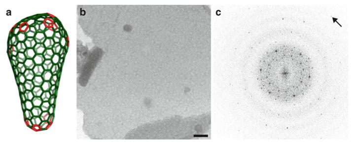
(a) Fullerene cone model of the HIV capsid in which a continuously variable hexagonal lattice of CA hexamers (green) is closed by insertion of exactly 12 CA pentamers (red), seven at the wide end, and five at the narrow end of the cone (16). (b ) 2D crystals of HIV CA grown by sparse matrix screening. The hexagonal lattice is an in vitro symmetric mimic of the variable hexagonal lattice in pleomorphic capsids of HIV. (c ) Fourier transform of an image of a flattened sphere (b) formed by a single layer of HIV CA hexamers preserved in vitreous ice, collected at 0 ° tilt (arrow points to a reflection at 9.8 Å). The transform displays two superimposed hexameric lattices that arise from the top and bottom layers of the flattened sphere (From ref. (14) and reproduced by permission from Cell press).
Fig. 5.
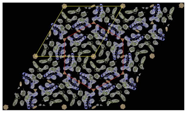
The 3D cryoEM density map of HIV-1 CA (gray-scale, mesh) at 9-Å in-plane resolution serves as a template for docking the high-resolution structures of the N-terminal (green ) and C-terminal (blue ) domains. A hexamer of N-terminal domains is outlined in red, and the p6 unit cell is outlined in yellow. The hexamers are linked together by dimers of the C-terminal domains (blue ). The six, three, and twofold symmetry axes are indicated by hexagons, triangles, and ellipses, respectively (From ref. (14) and reproduced by permission from Cell press).
If conditions for growing 3D crystals have been identified, a refinement of the sparse matrix approach is to directly apply an aliquot of the protein and precipitant solution to an EM grid and perform a time-course experiment to screen for nucleation of 2D crystals. Fine screening around the conditions for growing 3D crystals can also be performed. This approach was successful for generating 2D crystals of myosin II, in which the a and b lattice planes of the 2D crystals corresponded to similar planes in the 3D crystals (15).
2. Materials
2.1. Equipment
2.1.1. Lipid Monolayer 2D Crystallization
Teflon block (25 × 25 × 5 mm) with wells 3 mm in diameter (Fig. 6).
Hamilton syringe (10, 50, and 100 μl) (Fisher).
5 cm Whatman filter paper #2 (Fisher).
5 cm plastic Petri dish (Fisherbrand).
Parafilm™.
EM forceps (Dumont #5).
Fig. 6.
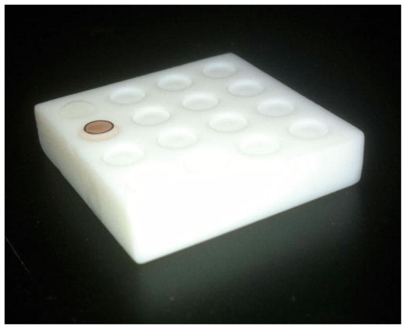
Teflon block used for lipid monolayer crystallization. The wells are 3 mm in diameter to accommodate the EM grid and have a depth of 0.5 mm.
2.1.2. Sparse Matrix Screening
600 μl Eppendorf, 8-tube pcr strip (Fisher) (Fig. 7).
96-well plate (Fisherbrand).
EM forceps (Dumont #5).
Fig. 7.
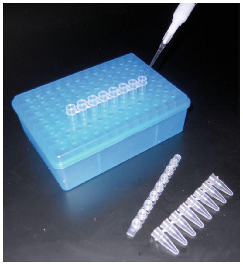
600 μl Eppendorf, 8-tube pcr strip, for sparse matrix screening. An aliquot of the precipitant solution is mixed with an aliquot of the solution containing the protein to be crystallized.
2.2. Reagents and Solutions
Egg PC (l-α-phosphatidylcholine) (Avanti Polar Lipids) (see Note 1).
2.2.1. Lipid Monolayer 2D Crystallization
Nickel-charged 1,2-dioleoyl-sn-glycero-3-((N-(5-amino-1-carboxypentyl)iminodiacetic acid)succinyl) (DOGS-NTA Ni2+) (Avanti Polar Lipids).
Hexane (Sigma).
Chloroform (Sigma).
Fisher Cleaning Solution.
7×, Linbro or Versa-Clean, Fisher.
Double-distilled, deionized water.
Uranyl acetate (Ted Pella).
3 mm Copper grids, 300 mesh (Ted Pella or EMS).
2.2.2. Sparse Matrix Screening
Solutions for 3D crystallization screens (e.g., Hampton Research, Wizard and Qiagen).
Uranyl acetate (Ted Pella).
3 mm Copper grids, 300 mesh (Ted Pella or EMS).
3. Methods
3.1. Lipid Monolayer 2D Crystallization
Fresh lipid solutions are prepared in chloroform and hexane from stock solutions of the special lipid (i.e., charged or liganded) and egg phosphatidylcholine and maintained on ice. Crystallization trials are performed in which the ratio of the special lipid to the bulk lipid is varied from 0 (as a control) to 1. A successful concentration for crystallization of MuLV CA was 50 mg/ml egg phosphatidylcholine and 12.5 mg/ml DOGS-NTA Ni2+ (12). Egg phosphatidylcholine is typically used because it remains fluid over a wide range of temperatures and compressions.
A teflon block (Fig. 1) that has wells 3 mm in diameter, corresponding to the diameter of an EM grid, is thoroughly cleaned in chromic and sulfuric acid (Fisher Cleaning Solution). The block is washed by sonication for 30 min in detergent solution (7×, Linbro or Versa-Clean, Fisher) and then rinsed for ~30 min in double-distilled, deionized H2O.
To maintain a hydrated atmosphere, filter paper is placed on the bottom of a 5 cm Petri dish and thoroughly wetted with buffer. The teflon block is then inserted.
Use an Eppendorf pipette to place a 10 μl droplet of the protein solution at a concentration of 0.5–1.0 mg/ml in the center of the 0.5 mm deep well (see Note 2).
Use a glass micropipette (e.g., Hamilton syringe) to add ~0.5–1.0 μl of the lipid solution to the top of the drop, which will lower the surface tension and flatten the droplet, but should not overflow the well.
Cover the Petri dish and seal with Parafilm. Incubate at the desired temperature (e.g., room temperature or 4 °C).
2D crystallization on the lipid monolayer can occur quickly (30–60 min) or take days.
EM grids with a hydrophobic carbon substrate are used since the attachment occurs via the lipid aliphatic chains.
EM forceps are used to carefully place the grid on top of the droplet with the carbon side facing the aliphatic chains on the droplet surface.
For some systems, a clue whether crystals have formed is that the grid will not rotate or spin when placed on the droplet.
The grid is immediately removed from the droplet or allowed to sit for 30 s and carefully lifted off (see Note 3). For staining, the grid is rinsed once on a droplet of distilled, deionized H2O, blotted with filter paper, and stained. For freezing, the grid is immediately blotted and plunged into a liquid ethane slush.
Alternatively, the surface of the droplet can be picked up with a platinum/paladium wire loop via surface tension (17). The loop has a diameter slightly larger than the EM grid, so that transfer to the grid is accomplished by carefully passing the grid through the loop.
3.2. Sparse Matrix Screening for 2D Crystallization
Mix 5 μl protein solution with 5 μl of a given crystal screen in either a 600 μl Eppendorf, 8-tube pcr strip (Fig. 5), or a 96-well plate, and mix rapidly by pipetting up and down several times (see Note 4).
Incubate the reactions overnight at room temperature or 3–4 h at 37 °C. Obviously, time and temperature can be varied, but since there is no diffusion step, the reaction reaches completion (see Note 5).
Pipete 3 μl of sample onto an EM grid.
For staining, the grid is rinsed once on a droplet of either distilled, deionized H2O or 0.1 M KCl (in the case of HIV CA), blotted with filter paper, and stained, or simply stained directly (see Note 6). For freezing, the grids need to be thoroughly washed to remove precipitants and buffers. In general, we use a 3 ml syringe equipped with a 0.2 μM filter to wash the grid with 5–10 drops of distilled, deionized H2O or 0.1 M KCl.
4. Notes
4.1. Lipid Monolayer 2D Crystallization
In general, lipids are stored as 10× stock solutions (e.g., ~2 mg/ml of the egg lipids and 0.5 mg/ml of the nickel lipids). For our experiments on MuLV CA, lipids are mixed with equal amounts of hexane and chloroform (i.e., 10 μl of 10× egg lipid, 10 μl 10× nickel lipid, 40 μl hexane, and 40 μl chloroform) as the base.
2D crystallization may be impeded if the sample buffer contains high concentrations of glycerol or salt. Hence, the sample may need to be diluted just before addition to the well in the teflon block.
It is essential that the grid be lifted from the droplet with as little disturbance as possible. Any rotation or translation of the grid will fracture the crystals.
4.2. Sparse Matrix Screening for 2D Crystallization
Due to volume restraints in robotic 3D crystallization, small amounts of the screening solutions are often discarded by users. These small aliquots are an excellent source for 2D screening buffers.
The protein should be concentrated to 2–30 mg/ml in a suitable buffer. Although low concentrations of buffer and salt are ideal, it is often not necessary for screening.
Some of the chemicals in the crystal screens will likely precipitate in the presence of uranyl acetate. Despite considerable precipitation, grids can still be screened and crystals still visualized.
Acknowledgments
Work in the Yeager laboratory is supported currently by NIH grants R01 HL48908, R01GM066087, R01 GM084545, and P50 GM082545. Parts of this review were abstracted from (2).
References
- 1.McPherson A. Preparation and analysis of protein crystals. Wiley; New York: 1982. [Google Scholar]
- 2.Yeager M, Unger VM, Mitra AK. Three-dimensional structure of membrane proteins determined by two-dimensional crystallization, electron cryomicroscopy, and image analysis. Methods Enzymol. 1999;294:135–180. doi: 10.1016/s0076-6879(99)94010-7. [DOI] [PubMed] [Google Scholar]
- 3.Adair BD, Yeager M. Electron microscopy of integrins. Methods Enzymol. 2007;426:337–373. doi: 10.1016/S0076-6879(07)26015-X. [DOI] [PubMed] [Google Scholar]
- 4.Hemming SA, Bochkarev A, Darst SA, Kornberg RD, Ala P, Yang DSC, Edwards AM. The mechanism of protein crystal growth from lipid layers. J Mol Biol. 1995;246:308–316. doi: 10.1006/jmbi.1994.0086. [DOI] [PubMed] [Google Scholar]
- 5.Brisson A, Olofsson A, Ringler P, Schmutz M, Stoylova S. Two-dimensional crystallization of proteins on planar lipid films and structure determination by electron crystallography. Biol Cell. 1994;80:221–228. [PubMed] [Google Scholar]
- 6.Chiu W, Avila-Sakar AJ, Schmid MF. Electron crystallography of macromolecular periodic arrays on phospholipid monolayers. Adv Biophys. 1997;34:161–172. doi: 10.1016/s0065-227x(97)89638-4. [DOI] [PubMed] [Google Scholar]
- 7.Ribi HO, Ludwig DS, Mercer KL, Schoolnik GK, Kornberg RD. Three-dimensional structure of cholera toxin penetrating a lipid membrane. Science. 1988;239:1272–1276. doi: 10.1126/science.3344432. [DOI] [PubMed] [Google Scholar]
- 8.Darst SA, Ahlers M, Meller PH, Kubalek EW, Blankenburg R, Ribi HO, Ringsdorf H, Kornberg RD. Two-dimensional crystals of streptavidin on biotinylated lipid layers and their interactions with biotinylated macromolecules. Biophys J. 1991;59:387–396. doi: 10.1016/S0006-3495(91)82232-9. [DOI] [PMC free article] [PubMed] [Google Scholar]
- 9.Kubalek EW, Le Grice SFJ, Brown PO. Two-dimensional crystallization of histidine-tagged, HIV-1 reverse transcriptase promoted by a novel nickel-chelating lipid. J Struct Biol. 1994;113:117–123. doi: 10.1006/jsbi.1994.1039. [DOI] [PubMed] [Google Scholar]
- 10.Barklis E, McDermott J, Wilkens S, Schabtach E, Schmid MF, Fuller S, Karanjia S, Love Z, Jones R, Rui Y, Zhao X, Thompson D. Structural analysis of membrane-bound retrovirus capsid proteins. EMBO J. 1997;16:1199–1213. doi: 10.1093/emboj/16.6.1199. [DOI] [PMC free article] [PubMed] [Google Scholar]
- 11.Lebeau L, Lach F, Vénien-Bryan C, Renault A, Dietrich J, Jahn T, Palmgren MG, Kühlbrandt W, Mioskowski C. Two-dimensional crystallization of a membrane protein on a detergent-resistant lipid monolayer. J Mol Biol. 2001;308:639–647. doi: 10.1006/jmbi.2001.4629. [DOI] [PubMed] [Google Scholar]
- 12.Ganser BK, Cheng A, Sundquist WI, Yeager M. Three-dimensional structure of the M-MuLV CA protein on a lipid monolayer: a general model for retroviral capsid assembly. EMBO J. 2003;22:2886–2892. doi: 10.1093/emboj/cdg276. [DOI] [PMC free article] [PubMed] [Google Scholar]
- 13.Dryden KA, Crowley CS, Tanaka S, Yeates TO, Yeager M. Two-dimensional crystals of carboxysome shell proteins recapitulate the hexagonal packing of three-dimensional crystals. Protein Sci. 2009;18:2629–2635. doi: 10.1002/pro.272. [DOI] [PMC free article] [PubMed] [Google Scholar]
- 14.Ganser-Pornillos BK, Cheng A, Yeager M. Structure of full-length HIV-1 CA: a model for the mature capsid lattice. Cell. 2007;131:70–79. doi: 10.1016/j.cell.2007.08.018. [DOI] [PubMed] [Google Scholar]
- 15.Turbedsky K, Pollard TD, Yeager M. Assembly of Acanthamoeba myosin-II minifilaments. Model of anti-parallel dimers based on EM and X-ray diffraction of 2D and 3D crystals. J Mol Biol. 2005;345:363–373. doi: 10.1016/j.jmb.2004.10.048. [DOI] [PubMed] [Google Scholar]
- 16.Ganser-Pornillos BK, Yeager M, Sundquist WI. The structural biology of HIV assembly. Curr Opin Struct Biol. 2008;18:203–217. doi: 10.1016/j.sbi.2008.02.001. [DOI] [PMC free article] [PubMed] [Google Scholar]
- 17.Asturias FJ, Kornberg RD. A novel method for transfer of two-dimensional crystals from the air/water interface to specimen grids. EM sample preparation/lipid-layer crystallization. J Struct Biol. 1995;114:60–66. doi: 10.1006/jsbi.1995.1005. [DOI] [PubMed] [Google Scholar]