

Abstract
Improving the health outcomes for end-stage renal Disease (ESRD) patients on hemodialysis (HD) requires new technologies for wearable HD such as a highly efficient membrane that can achieve standard toxic clearance rates in small device footprints. Our group has developed nanoporous silicon nitride (NPN) membranes which are 100 to 1000 times thinner than conventional membranes and are orders-of-magnitude more efficient for dialysis. Counter flow dialysis separation experiments were performed to measure urea clearance while microdialysis experiments were performed in a stirred beaker to measure the separation of cytochrome-c and albumin. Hemodialysis experiments testing for platelet activation as well as protein adhesion were performed. Devices for the counter flow experiments were constructed with polydimethylsiloxane (PDMS) and a NPN membrane chip. The counter flow devices reduced the urea by as much as 20%. The microdialysis experiments showed a diffusion of ~60% for the cytochrome-c while clearing ~20% of the Albumin. Initial hemocompatibility studies show that the NPN membrane surface is less prone to both protein adhesion and platelet activation when compared to positive control (glass).
I. Introduction
There were ~680,000 patients with end-stage renal Disease (ESRD) in the US in 2014 with ~121,000 new cases reported [1]. The standard of care for ESRD patients is lifelong HD treatments at a frequency of three times per week with 63.4% of prevalent ESRD cases undergoing HD in 2014 (98% in centers, 2% at home). In-center thrice-weekly treatments have been linked with significantly increased risk of cardiovascular disease (CVD) events and mortality due to the increased interdialytic period [2]. Even with frequent HD, life expectancies for ESRD patients aged 30 to 85 years are typically less than 10.5 years [3]. Post dialysis recovery time can be twice as long as the treatment time, during which time patients report feeling ill, rundown, and depressed.
A prerequisite for portable, wearable, and implantable HD systems is the development of highly efficient membranes that can achieve standard toxin clearance rates in small device footprints. Conventional HD uses membranes that are ~10 microns thick with tortuous flow paths. These characteristics slow diffusion and convection through membranes. Consequently, dialyzers incorporating these membranes require long flow channels (15″ to 18″) and large membrane surface areas (1.4 m2 to 2.4 m2) to achieve target clearance values. Our group has developed nanoporous silicon nitride (NPN) membranes for inclusion in a small format HD device. These membranes, which were first described by our group four years ago [4], are 100 to 1000 times thinner than conventional HD membranes and are therefore orders-of-magnitude more efficient for dialysis [5]. In fact, given the molecular thickness of these membranes (~15 nm to ~75 nm) and their appreciable porosity (~15%), NPN membranes operate near the maximum permeability that is achievable for a nanoporous membrane [5–10]. These characteristics also make the NPN membranes highly selective [11, 12] and therefore candidates for next generation hemodialysis membranes. Additionally, the membrane pore sizes can be tuned to match specific molecular separation goals [13] and the silicon platform allows for scalable manufacturing and straightforward integration with fluidics. Other groups are also working on silicon-based filter membranes [14] but have not achieved the thinness of our nanoporous nitride membranes and therefore cannot achieve the clearance rates with the same surface area.
Many significant changes have been made to hemodialysis device technology since Dr. Willem Kolff constructed the first dialyzer in 1943. Advances in HD technology continue to improve the dialysis machines, adding functionality and safety features. However, since the 1970’s the filtration material has remained fundamentally the same, specifically maintaining the same basic size and form. Various research groups have been working to develop miniaturized hemodialysis devices [15–18]. The small size of these devices, with lower flow rates and reduced extracorporeal volume, preclude testing with the current HD delivery systems, especially those that involve a major change in the dialyzer format. This points to a need for reliable, efficient, and cost-effective testing methods for small format dialyzers. As a first step, characterization studies were performed on nanoporous nitride (NPN) membranes included in a small format HD device for bench top studies.
Here we report on the results of these bench top studies. We describe the design and operation of a small benchtop microfluidic system that explores urea dialysis clearance predicted from finite element models of our system. We also report on the initial hemocompatibility studies, protein adhesion and platelet activation, of the NPN membrane chips used in the clearance studies.
II. Membrane Formation and Characterization
The ultrathin NPN membranes are fabricated in silicon chips via a transfer etch process [4]. The pore pattern is formed into a hard mask on the surface of a silicon wafer by rapid thermal annealing of a stack of materials whose properties, along with the anneal parameters, control the pore size and density [12]. The porous poly-nanocrystalinesilicon (pnc-Si) can be used as a hard mask as is or after an oxidizing process, which strengthens it for use as a hard mask during more mechanically intensive lithography processes. The pores are then etched through this hard mask into an underlying nitride layer creating a nanoporous nitride (NPN) layer. Membranes created with the oxidized pnc-Si are designated NPN-O membranes. By etching through the backside of the wafer, channels are formed exposing the underside of the membranes and individual chips are delineated. The resulting NPN and NPN-O membranes are ultrathin, 50 nm to 100 nm, with pore sizes from 30 nm to 45 nm. The process is illustrated in Figure 1A. The sieving curves, which show the size separation characteristics of the membranes, are shown in Figure 1B. Notice how the ‘cutoff’ size for the 50 nm NPN-O membranes is much lower than the 50 nm NPN membranes (~10 nm v ~30 nm).
Figure 1.
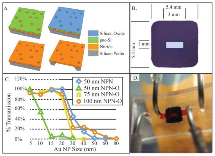
A. Membrane Fabrication. Thick NPN-O process starts with 75 nm thick silicon Nitride layer below nanoporous pnc-Si mask. Oxidation step thickens and strengthens mask allowing for long DRIE etch though 75 nm silicon Nitride Channels etched in Si substrate forming membrane regions. B: Nanoporous silicon nitride filter chip. Active membrane are (center of chip) is 1 mm × 3 mm) C. Sieving curves for the various membranes comparing membrane thickness and old non-Oxide process. D. Chip shown in fluidic device, upper channel (filled with red fluid) passes into trench in membrane surface. Lower channel (outboard ports) passes along the flat bottom of the chip.
III. Device and Modeling
Devices are constructed with a single membrane chip, several layers of silicone gasket material, and an upper layer of PDMS (which holds the inlet/outlet tubing). All the layers are bonded, along with the chip, on top of a microscope coverslip (to provide stability and microscopy compatibility) via an ozone bonding process. The device can be seen in Figure 1D. A finite element model was constructed of the single chip system in three dimensions using the COMSOL Multiphysics 5.3 software package (see Figure 2) to provide a theoretical instantaneous clearance value for comparison with clearance values obtained in the single pass dialysis experiments. The analytes flow through the upper channels into the trench etched into the silicon chip and come in to contact with the nanoporous membrane. Dialysate (clean PBS) flows in the opposite direction in the lower channel and contacts the membrane on the flat side of the chip. Diffusion coefficient of urea in PBS was set to 1.38e-9 m2/s while the value used for the membrane was decreased to account for the porosity of the membrane, 15% (and scaled for the model geometry as the 75 nm membrane was drawn as 75 mm).
Figure 2.
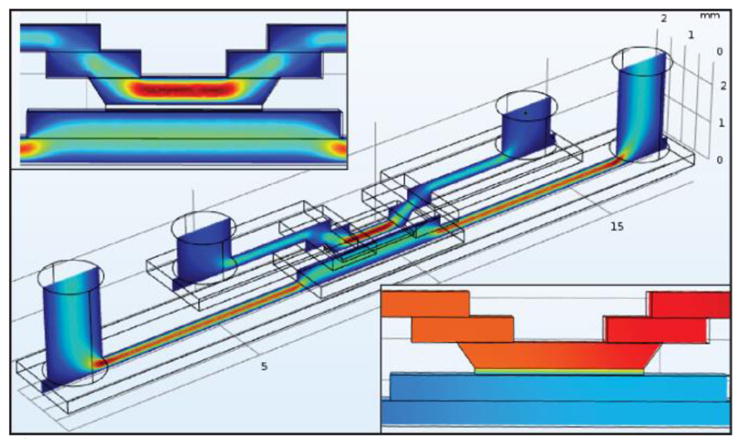
Upper Callout: 3D fluid velocity in COMSOL. Cente: 3D Fluid volume model, Analyte flows through upper channel in the chip and Dialysate flows across flat side of chip in lower flow channel. Lower Callout: Urea Concentration shown in central portion of device, Urea at 100% concentration enters in upper right channel, exits at 80% on left.
IV. Single-Pass Bench-Top Dialysis
This experiment was designed to explore the membrane permeability in a small dialysis format. The flow rate was bound on the lower end by the need to have the necessary volume of fluid for the colorimetric assays. On the upper end, there was no specific cut off, only that our COMSOL model suggested that the clearance increased as the flow rate decreased. The analyte fluid, comprised of 5 mM urea and fetal bovine serum, was passed over the top side (trench) of the membrane while PBS (dialysate) was passed on the underside (flat surface of the chip). The flow rates for the analyte and dialysate are 1 μL/min and 2 μL/min respectively. The dialysate flow rate was twice that of the analyte to prevent ultrafiltration rates that could complicate the clearance calculations. The set up, which used syringe pumps to deliver the fluids and a fraction collector, allowed for fully automated collection of samples over the entirety of the experiment, giving the user flexibility in designing long experiments with many sample collections. For our current research, we collected samples every hour for 6 hours. In this format, we expect to see steady clearance of urea of approximately 15% to 20% as determined by the COMSOL model. The lack of specificity of these initial models is due to the variability of the diffusion coefficients used for both the analyte fluid and in the membrane.
V. Microdialysis Retention
While the above experiments aimed to probe the NPN membranes for urea diffusion, the results are a measure of the system itself and not indicative of the membrane separation characteristics. To address this question without complications of fluid flow, we used an open bottom SepCon based experiment that addressed separation through diffusion. The analyte comprised of 1 mg/ml BSA and cytochrome C and PBS was introduced to the top of the column (50 μL) placed in a clean beaker was filled with PBS. The system was placed on a magnetic stir plate in the refrigerator (6 °C) and left to separate for 24 hours; enough time for both BSA and cytochrome c to diffuse into the beaker at equilibrium if the membrane did not hinder their progress.
VI. Hemocompatibility
A. FITC-BSA Adsorption
We studied the adsorption of fluorescent protein (BSA) on nanoporous nitride membrane (NPN) chips using epifluorescence as the imaging modality. NPN chips were incubated (membrane side up) in 1 mg/mL of FITC-BSA for 1 hour, then rinsed/washed in DiH2O and let dry. The NPN chips were then flipped upside down onto a U-shaped gasket (to suspend the membrane from contact) for imaging on an inverted microscope. In this study, glass was chosen as the positive control for protein adsorption.
B. Platelet Activation
Substrates (glass and nanoporous nitride) were incubated with plasma rich platelets for two hours, then all samples were inverted upside down and let sit for 30 min to allow unbound platelets to detach by gravity. The samples were washed with PBS, before being fixed via 4% paraformyldehyde (20 min). The samples were blocked with BSA (20 mg/mL) for 1 hour at RT, followed by incubation with primary antibodies, 20 μg/mL CD62P (label for platelet activation) and 20 μg/mL CD41 (label for platelet adhesion) (Abcam, Cambridge, MA) overnight at 4°C then incubated with the secondary antibodies, AF488 goat anti-mouse (100 μg/mL) and AF568 goat anti-rabbit (100 μg/mL) (Abcam, Cambridge, MA), for 1 hour.
The samples were then washed in DiH2O and let dry before imaging. DiH2O was used instead of PBS since salt crystals tend to reduce image clarity. The substrates where then imaged with a fluorescence microscope and analyses for intensity and reported as the degree of platelet activation.
VII. Results
A. Single-Pass Bench-Top Dialysis
In the counter-flow experiment, 20% of the urea was diffused through the membrane into the dialysate fluid. This is in agreement with the expected values from the COMSOL model. Fluid change was monitored to ensure that analyte dilution did not occur due to negative ultrafiltration of dialysate into the analyte fluid. The clearance was stable over the run of the experiment. Data points from hours four and six are shown in Figure 3A. Importantly, urea was cleared with very little membrane surface area, 1.4 mm2.
Figure 3.

A: Single Pass Small-molecule clearance in a counter-flow system at 4 hours and 6 hours B: Microdialysis separation of BSA and Cytochrome-C C: Comparison of Albumin adsorption on Glass, and NPN D: Platelet Activation on Glass and NPN
B. Microdialysis Retention
Results showed a large reduction in cytochrome-c and a smaller reduction for BSA over 24 hours (>55% reduction cytochrome-c, < 20% reduction BSA) as shown in Figure 3B. The data suggests the membranes are less permeable to albumin then cytochrome c as expected and a requirement for hemodialysis membranes. This indicates that the molecular weight cut-off was somewhere between the size of cytochrome-C (12 kDa) and that of albumin (66.5 kDa).
C. Hemocompatibility
FITC-BSA Adsorption: The results (see Figure 3C) show that there is a significant reduction of the adsorption of the protein on the NPN membrane compared to glass, the positive control. This is as expected and provides a starting point for future improvements via surface functionalization.
Platelet Activation
Platelet activation is also reduced on the NPN membrane surface compared to the positive control (see Figure 3D). The error bar represents the standard error of the mean. For each substrate type there are three samples with five regions on each sample analyzed. Again, this a an indication that while the activation is improved, additional steps must be taken to reduce this even further.
VIII. Conclusion
The positive results from the urea clearance with the NPN membranes, which reduced the urea by 20%, show how efficient the ultrathin membranes are in a microfluidic format. These chips and devices will continue to be used to gather information on the diffusion of various molecules under different situations, (e.g. flow rates, functionalization, complex protein fluids). This result will also be used to determine the diffusion coefficient for urea in water through the membrane in order to determine coefficients for proteins of various sizes for membranes with different pore sizes and porosities. The microdialysis experiments showed that not only will small molecules diffuse through the membranes, but larger molecules with be held back providing good separation. This basic cut-off experiment will aid in characterizing chip-based membranes with a variety of parameters (e.g. pore size, porosity, membrane thickness). The presence of protein adsorption and platelet activation, even though less than the positive control, points to the need for more careful design of the fluid flow in future experiments, as well as the need for surface functionalization, which our group has developed for nitride surfaces [19].
The top barriers to adoption of home-based HD include, space for equipment and supplies, lack of support/care partner, training/education limitations, self-cannulation, and medicalization of the home [20–23]. All of these hindrances can be ameliorated, to some extent, with the small form factor devices that our membranes can bring to market. The smaller size of our filters and the associated reduction in amount of extracorporeal blood flow will enable the substantial reduction in the size and complexity of the dialysis equipment. The low flow rates will enable the use of smaller needles for less intimidating self-cannulation. The small size of the equipment reduces the space requirements, minimizing the medicalization effect in the home.
Patients adopting home hemodialysis can experience immediate benefits such as lifestyle normality, satisfying self-sufficiency, personalized treatment, and a positive treatment environment [22]. There are dialysis centers (e.g. Rubin Hemodialysis Center) that allow in-center patients to experience the home hemodialysis equipment while in their center, which gives the patients a chance to better understand the benefits as well as the procedures without having to commit to home treatments first. They find this early motivation promotes adoption of home hemodialysis (20%) above the national average (2%).
This approach, coupled with a smaller, more efficient device that requires lower blood flow rates, should positively impact the adoption rate of home hemodialysis devices. This transition, however, does not come without challenges; small device sizes with the accompanying lower flow rates and reduced extracorporeal volume, preclude testing with the current HD delivery systems, especially those that involve a major change in the dialyzer format. This points to a need for reliable, efficient, and cost-effective testing methods for small format dialyzers. Our next steps are to design, build, and test an in vitro model of the concentration of middleweight molecules in the intravascular fluid volume (blood) and arteriovenous fistula access for hemodialysis that can be used to test both commercial hemodialysis machines and miniaturized HD delivery systems.
The present work has shown these NPN membranes to be capable of performing the filtration required for hemodialysis. Further work, including surface treatment and characterization, is required to achieve viable implementation of these NPN membranes in hemodialysis devices.
Acknowledgments
Research supported by NIH/NIDDK K25 DK106503-01A1 and Fresenius Medical.
Contributor Information
Alec Salminen, Biomedical Engineering Department, University of Rochester, Rochester, NY 14627 USA.
Kayli Hill, Biomedical Engineering Department, University of Rochester, Rochester, NY 14627 USA.
Henry L. Chung, Biomedical Engineering Department, Rochester Institute of Technology, Rochester, NY 14623 USA
James L. McGrath, Biomedical Engineering Department, University of Rochester, Rochester, NY 14627 USA
Dean G. Johnson, Biomedical Engineering Department, University of Rochester, Rochester, NY 14627 USA.
References
- 1.USRDS. 2016 USRDS annual data report: Epidemiology of kidney disease in the United States. National Institutes of Health, National Institute of Diabetes and Digestive and Kidney Diseases; Bethesda, MD: 2016. [Google Scholar]
- 2.Foley RN, Gilbertson DT, Murray T, Collins AJ. Long interdialytic interval and mortality among patients receiving hemodialysis. doi: 10.1056/NEJMoa1103313. (in eng), no. 1533–4406 (Electronic), 20111013 DCOM- 20111019 2011. [DOI] [PubMed] [Google Scholar]
- 3.Turin TC, Tonelli M, Manns BJ, Ravani P, Ahmed SB, Hemmelgarn BR. Nephrol Dial Transplant. 8. Vol. 27. England: 2012. Chronic kidney disease and life expectancy; pp. 3182–6. [DOI] [PubMed] [Google Scholar]
- 4.DesOrmeaux JP, et al. Nanoporous silicon nitride membranes fabricated from porous nanocrystalline silicon templates. 2014 doi: 10.1039/c4nr03070b. (in eng), no. 2040–3372 (Electronic), 20140822. [DOI] [PubMed] [Google Scholar]
- 5.Snyder JL, et al. An experimental and theoretical analysis of molecular separations by diffusion through ultrathin nanoporous membranes. Journal of Membrane Science. 2011;369(1–2):119–129. doi: 10.1016/j.memsci.2010.11.056. [DOI] [PMC free article] [PubMed] [Google Scholar]
- 6.Gaborski TR, et al. High-performance separation of nanoparticles with ultrathin porous nanocrystalline silicon membranes. ACS Nano. 2010;4(11):6973–6981. doi: 10.1021/nn102064c. [DOI] [PMC free article] [PubMed] [Google Scholar]
- 7.Striemer CC, Gaborski TR, Fang DZ, Snyder JL, McGrath JL, Fauchet PM. Porous ultrathin silicon membranes for purification of nanoscale materials. 2009 MRS Fall Meeting, November 29, 2009 - December 2, 2009; Boston, MA, United states. Materials Research Society; 2010. pp. 95–100. [Google Scholar]
- 8.Agrawal AA, et al. Porous nanocrystalline silicon membranes as highly permeable and molecularly thin substrates for cell culture. Biomaterials. 2010 Jul;31(20):5408–17. doi: 10.1016/j.biomaterials.2010.03.041. (in eng) [DOI] [PubMed] [Google Scholar]
- 9.Chung HH, et al. Highly permeable silicon membranes for shear free chemotaxis and rapid cell labeling. Lab Chip. 2014 Jul 21;14(14):2456–68. doi: 10.1039/c4lc00326h. (in eng) [DOI] [PMC free article] [PubMed] [Google Scholar]
- 10.Qi C, Striemer CC, Gaborski TR, McGrath JL, Fauchet PM. Highly porous silicon membranes fabricated from silicon nitride/silicon stacks. Small. 2014 Jul 23;10(14):2946–53. doi: 10.1002/smll.201303447. (in eng) [DOI] [PubMed] [Google Scholar]
- 11.Burgin T, Johnson D, Chung H, Clark A, McGrath J. Analytical and finite element modeling of nanomembranes for miniaturized, continuous hemodialysis. Membranes. 2015;6(1):1–14. doi: 10.3390/membranes6010006. [DOI] [PMC free article] [PubMed] [Google Scholar]
- 12.Striemer CC, Gaborski TR, McGrath JL, Fauchet PM. Charge- and size-based separation of macromolecules using ultrathin silicon membranes. Nature. 2007 Feb;445(7129):749–53. doi: 10.1038/nature05532. (in eng) [DOI] [PubMed] [Google Scholar]
- 13.Fang DZ, Striemer CC, Gaborski TR, McGrath JL, Fauchet PM. Methods for controlling the pore properties of ultra-thin nanocrystalline silicon membranes. Journal of Physics Condensed Matter. 2010;22(45) doi: 10.1088/0953-8984/22/45/454134. [DOI] [PubMed] [Google Scholar]
- 14.Kim S, et al. Diffusive Silicon Nanopore Membranes for Hemodialysis Applications. PLoS One. 2016;11(7):e0159526. doi: 10.1371/journal.pone.0159526. (in eng) [DOI] [PMC free article] [PubMed] [Google Scholar]
- 15.Fissell WH, Roy S. The implantable artificial kidney. 2009 doi: 10.1111/j.1525-139X.2009.00662.x. (in eng), no. 1525-139X (Electronic), 20091218 DCOM- 20100401. [DOI] [PubMed] [Google Scholar]
- 16.Johnson DG, et al. Ultrathin Silicon Membranes for Wearable Dialysis. Advances in chronic kidney disease. 2013;20(6):508–515. doi: 10.1053/j.ackd.2013.08.001. [DOI] [PubMed] [Google Scholar]
- 17.Gura V, Macy AS, Beizai M, Ezon C, Golper TA. Technical Breakthroughs in the Wearable Artificial Kidney (WAK) Clinical Journal of the American Society of Nephrology. 2009;4(9):1441–1448. doi: 10.2215/CJN.02790409. [DOI] [PMC free article] [PubMed] [Google Scholar]
- 18.Ahmadi M, Gorbet M, Yeow JT. In vitro clearance and hemocompatibility assessment of ultrathin nanoporous silicon membranes for hemodialysis applications using human whole blood. Blood Purif. 2013;35(4):305–13. doi: 10.1159/000350613. (in eng) [DOI] [PubMed] [Google Scholar]
- 19.Li X, et al. Modification of Nanoporous Silicon Nitride with Stable and Functional Organic Monolayers. Chemistry of Materials. 2017;29(5):2294–2302. doi: 10.1021/acs.chemmater.6b05392. [DOI] [PMC free article] [PubMed] [Google Scholar]
- 20.Yau M, Carver M, Alvarez L, Block GA, Chertow GM. Understanding barriers to home-based and self-care in-center hemodialysis. Hemodial Int. 2016 Apr;20(2):235–41. doi: 10.1111/hdi.12357. (in eng) [DOI] [PubMed] [Google Scholar]
- 21.Metzger S. Home Dialysis Modalities: Educational Barriers to Utilization. Nephrol Nurs J. 2016 May-Jun;43(3):251–4. (in eng) quiz 255. [PubMed] [Google Scholar]
- 22.Hanson CS, et al. Patient experiences of training and transition to home haemodialysis: a mixed-methods study, (in eng) Nephrology (Carlton) 2016 Jun 02; doi: 10.1111/nep.12827. [DOI] [PubMed] [Google Scholar]
- 23.Firanek CA, et al. Contrasting Perceptions of Home Dialysis Therapies Among In-Center and Home Dialysis Staff. Nephrol Nurs J. 2016 May-Jun;43(3):195–205. (in eng) [PubMed] [Google Scholar]