

Abstract
Background:
Axillary nerve injury and suture cutout through the roof of the tunnel are potential complications of arthroscopic transosseous rotator cuff repair (ATORCR).
Purpose:
To determine a safe angle of drilling for the bone tunnel during ATORCR such that the axillary nerve is not at risk. The thickness of the bone bridge over the tunnel for different angles of drilling was also determined.
Study Design:
Descriptive laboratory study.
Methods:
The drilling of a straight tunnel was simulated on 30 magnetic resonance imaging (MRI) scans in the oblique coronal plane by drawing a straight line that passed at a “safe distance” of 5 mm from the axillary nerve and emerging at the medial border of the insertion of the rotator cuff on the greater tuberosity. The angle made by this line with the horizontal axis of the humerus was measured on 3 MRI sections: anterior (passing just posterior to the lateral lip of the bicipital groove), middle (at the most lateral point of the proximal humerus), and posterior (an equal number of cuts away from the middle section as between anterior and middle). The thickness of the overlying bone roof was measured for this line as well as for simulation lines drawn at 50°, 55°, 60°, and 65° with the horizontal axis. A “safe limit,” defined as the mean – 2SD, was also calculated.
Results:
The axillary nerve was found to be safe, with a safety margin of 5 mm, at drill angles of less than 61.1° and 60.3° in the posterior and middle sections, respectively. The safe limit value for thickness of the overlying bone roof for the tunnel drilled at 60° was 5.0 mm in the posterior section (mean, 8.2 ± 0.3 mm) and 5.5 mm in the middle section (mean, 8.1 ± 0.2 mm). In the anterior section, the minimum safe angle was 57.7°, and the mean thickness of the bone roof for the 55° angle was 6.3 ± 0.2 mm (safe limit, 3.7 mm).
Conclusion:
Straight bone tunnels in ATORCR surgery should be drilled at an angle of 60° to the horizontal axis of the humerus or 30° to the humeral shaft to ensure the safety of the axillary nerve while at the same time ensuring adequate thickness of the overlying bone roof. The anterior tunnel close to the bicipital groove should be drilled cautiously at 55° to the horizontal axis or 35° to the humeral shaft.
Clinical Relevance:
The findings of the present study will help the surgeon choose the best angle for drilling tunnels during ATORCR surgery to avoid axillary nerve injuries as well as suture cut-through without the need for any proprietary device.
Keywords: arthroscopic transosseous, axillary nerve, rotator cuff
Arthroscopic repair with suture anchors is currently the most common method of rotator cuff repair. However, transosseous rotator cuff repair, first described in 1944 by McLaughlin, is considered the gold standard for rotator cuff surgery by many authors.13,21 Over the past few years, many authors have described slightly differing versions of arthroscopic transosseous rotator cuff repair (ATORCR).2,7,8,13,14,16,21 This method theoretically represents the best of both worlds, having the advantage of a minimally invasive arthroscopic procedure with the strength and cost-effectiveness of transosseous fixation.
Different surgical techniques of ATORCR have been described, with some using proprietary instrumentation, enabling a curved bone tunnel.2,13 On the other hand, the method involving drilling of straight tunnels using simple K-wires does away with the requirement of any proprietary instrumentation.16 With this method, however, there is a theoretical risk of injuries to the axillary nerve on the lateral surface of the humerus.16 No such cases of injuries have been reported to date, but the literature reporting on this method is still limited, and it is considered as a potential complication.16
Another important complication specific to this fixation method is cut-through of the suture through the bone bridge or roof overlying the tunnel.4,18 This can be prevented by having a sufficient bone bridge over the tunnel.8,14 A study assessing the best site for transosseous suture drilling over the lateral humerus found that the strength to failure could be increased if the tunnels were placed at least 10 mm distal to the tip of the greater tuberosity.6 However, while the distance from the greater tuberosity can be used as a reference point in open surgery, it is an unsuitable reference point in arthroscopic surgery. Some other reference point is required in this scenario, such as the angle made by the drill wire with the vertical axis. Further, the strength to failure would depend not only on this distance from the tuberosity but also on the thickness of the overlying bone roof.
Both these complications, axillary nerve injuries and bone cut-through, are linked to the angle at which the straight tunnel is made in the proximal humerus or, in other words, the angle at which the drill wire is drilled. The more acute the angle of drilling is with respect to the horizontal plane, the more proximal it will enter on the lateral humeral cortex, and the farther it will be from the axillary nerve. However, a smaller angle will also mean a thinner bone bridge over the tunnel, thus increasing the chances of suture cut-through. Thus, it is important for the operating surgeon to know the best angle of insertion at which not only the axillary nerve is safe but the bone bridge over the tunnel is adequate as well. To answer this question, the present magnetic resonance imaging (MRI)–based simulation study was performed (1) to determine the angle for drilling the bone tunnel at which the axillary nerve is not at risk during ATORCR and (2) to determine the thickness of the bone bridge over the tunnel for different angles of drilling.
Methods
The present study was an MRI simulation study. MRI scans of the shoulder obtained from patients aged 18 to 45 years for different abnormalities were collected for this study from the radiology service located in Safdarjung Hospital. Scans of patients with tumors, fractures, or bony deformities around the shoulder were excluded. Scans were obtained using a 1.5-T MRI machine (GE Healthcare). Prior ethical approval was attained from the hospital's ethics committee for use of these data and conducting this study.
Sample Size Calculation
No study in the literature has assessed the angle of wire passage in this scenario or assessed the location of the axillary nerve in terms of the angle created with any fixed axis by a line passing through the nerve. Hence, a pilot study was conducted on 10 MRI scans, and the angle made with the horizontal axis by a line passing 5 mm proximal to the nerve and exiting at the most medial point of insertion of the rotator cuff was measured using the method described below. This measurement was considered as the primary variable for sample size calculation. The SD for this angle was 5.2°. The angle that can be set in conventional angular jigs is generally at 5° intervals. With a confidence level of 0.95, the sample size needed for a desired total width of confidence interval equal to 5° for the angle made by the drilling wire was 17. A larger sample size of 30 was chosen.
MRI Sequence and Cuts Used
The images were obtained in the DICOM (Digital Imaging and Communications in Medicine) format, and all references to patient identification and demographics were removed from the images. A proton density–weighted 3-dimensional (3D) CUBE sequence in the oblique coronal plane taken in the plane of the body of the scapula was used. All the simulations and measurements in this study were performed with this sequence. This sequence was chosen based on the fact that the axillary nerve traverses almost horizontally over the lateral aspect of the humerus. As such, the course of the axillary nerve would be nearly perpendicular to the oblique coronal plane, and thus, the distance between the wire and the nerve in this plane would be the shortest (Figure 1).
Figure 1.

A diagrammatic representation of the oblique sagittal view through the axillary nerve over the lateral aspect of the humerus. Line PQ represents the horizontal plane, and its perpendicular line RS represents the oblique coronal plane. Let MN be the path of the axillary nerve over the lateral aspect of the humerus and W be the point where the drill wire passes through this section. Then, line WZ, perpendicular to MN, will be the actual minimum distance between the nerve and the wire, and line WO, drawn perpendicular to the horizontal axis, will be the distance measured on the oblique sagittal view. Assuming that the axillary nerve is nearly horizontal, that is, angle NOQ or OWZ is very small, the difference between the 2 distances will be nonsignificant.
With this sequence, 3 sections were chosen on each MRI scan: (1) anterior, passing just posterior to the lateral lip of the bicipital groove; (2) middle, at the level of the most lateral point of the proximal humerus; and (3) posterior, such that the distance of this posterior point from the middle section was the same (ie, equal number of cuts away) as the distance of the anterior section from the middle section (Figure 2). All measurements described below were made on each of these 3 sections.
Figure 2.

Selection of the 3 sections for measuring the angle of the bone tunnel and the thickness of the overlying bone bridge on oblique coronal magnetic resonance imaging. A, anterior section; B, bicipital groove; M, middle section; P, posterior section.
Identification of the Nerve
The axillary nerve was first identified passing from anterior to posterior through the quadrangular space using axial, oblique coronal, and oblique sagittal planes in the 3D CUBE sequence. It was further traced around the lateral cortex of the surgical neck of the humerus going from posterior to anterior. In this way, the location of the axillary nerve was identified and marked on the 3 selected oblique coronal images. Because tunnels are made with a K-wire drilled at a high speed, a safe margin from the nerve is required to keep the nerve out of harm’s way. In the present study, a distance of 5 mm from the axillary nerve was considered “safe,” based on the work of Cho et al.9 This margin of 5 mm would also take care of potential errors as well as statistical variability.
All measurements were performed on each of the 30 MRI scans by 2 authors separately (H.G. and P.M.). Additionally, the measurements on 10 scans were repeated by the first author (H.G.) after an interval of more than 15 days to measure test-retest reliability.
Anatomic Landmarks and Axes
The longitudinal (superoinferior) axis of the humeral shaft (line SI in Figure 3) was defined in the middle MRI section by drawing 2 circles inside the medullary canal, touching the cortices on the 2 sides and joining their centers. Another line (OY) parallel to the longitudinal axis was drawn, starting from the superior junction of the articular cartilage and the greater tuberosity (the most medial insertion of the rotator cuff). This point O represented the point where the drill wire would exit intra-articularly during surgery.
Figure 3.

Axes drawn on the middle section on oblique coronal magnetic resonance imaging. Line SI passes through the centers of 2 circles drawn inside and touches the walls of the medullary canals of the humerus. Line OY is parallel to SI. Line OX is perpendicular to OY, thus representing the horizontal axis. Line OA, passing through the axillary nerve, creates an angle of 76.5° with the horizontal axis in this case. A circle with a radius of 5 mm is drawn centered over the nerve, and line OB is tangential to this circle. It creates an angle of 68.4° with the horizontal axis.
The horizontal axis (line XO) was drawn perpendicular to the longitudinal axis. All angles were measured with respect to this horizontal axis.
Measurements
Line OA was drawn from point O, passing through the axillary nerve over the lateral humeral cortex, and its angle to the horizontal axis was measured (angle XOA) (Figure 3). This line simulated the passage of guide wire that would pass directly through the nerve.
A circle with a radius of 5 mm (diameter, 10 mm) was drawn around the axillary nerve, and another line OB was drawn from point O, superior to line OA and passing tangential to this circle, and angle XOB was measured (Figure 3). This line simulated the passage of the guide wire such that the shortest distance of the wire from the nerve would be 5 mm.
Another line, parallel to line OB (B1B2 in Figure 4), was drawn such that it passed tangential to the cortex of the greater tuberosity, and the perpendicular distance between these 2 lines was measured. This gave the thickness of the bone over the simulated tunnel OB (Figure 4).
Next, the thickness of the overlying bone bridge was determined for tunnel drilling simulated at various angles. For this, lines were drawn from point O at angles of 65°, 60°, 55°, and 50° with the horizontal axis, simulating wire passage at these angles. For each of these lines, a parallel line was drawn tangential to the greater tuberosity, and the perpendicular distance between them was measured, giving the thickness of the overlying bone roof. Figure 5 shows the measurement of bone thickness for drilling line OD at 60°.
The distance of the exit point of the tunnel over the lateral surface of the humerus from the tip of the greater tuberosity was also measured. For this, a line parallel to the horizontal axis was drawn through the tip of the tuberosity (O1X1 in Figure 6), and the perpendicular distance of the exit point of the tunnel from this line was measured (perpendicular distance between O1X1 and TX2 in Figure 6). The distance of the nerve from the tip of the greater tuberosity was also measured in a similar way (Figure 6).
Figure 4.

Measurement of the thickness of the bone over the tunnel. Line B1B2 is drawn parallel to line OB, such that it is tangential to the margin of the greater tuberosity. The distance between these 2 lines (8.8 mm in this case) gives the greatest thickness of the overlying bone.
Figure 5.
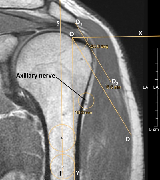
Measurement of the thickness of the bone over the tunnel for different angles of drilling. Here, line OD is drawn at an angle of 60° with the horizontal axis, and line D1D2 is parallel to line OD and tangential to the margin of the greater tuberosity. The distance between these 2 lines (6.5 mm) gives the thickness of the overlying bone.
Figure 6.

Measurement of the distance of the exit point of the tunnel over the lateral surface of the humerus (point T) from the tip of the greater tuberosity with a drill angle of 60°. Line O1X1, parallel to the horizontal axis, is drawn through the tip of the tuberosity. Another parallel line TX2 is drawn through point T, and the perpendicular distance between these lines is measured (18.9 mm). The distance of the nerve from the tip of the greater tuberosity is also measured in a similar way (distance between O1X1 and O3X3, which is 37.0 mm in this case).
Axillary nerve identification was performed on MRI workstations (Advantage Window version 4.6; GE Healthcare). All measurements were performed on JiveX DICOM viewer (VISUS Health IT).
Statistical Analysis
R Commander was used for statistical analysis.11,22 Interrater reliability between the 2 assessors and intrarater (test-retest) reliability were assessed for each variable separately using the intraclass correlation coefficient (ICC) as well as a paired t test. The values from the 2 assessors were then averaged for each data point, and this data set with averaged values was used for further calculations.
The normality of data for each variable was assessed using the Shapiro-Wilk test. The mean, range, SD, and 95% CI were calculated. The mean – 2SD value was also calculated. Because in a normally distributed population, 97.5% of the participants are expected to lie above the mean – 2SD value, this was used to define the “safe limit” for nerve safety as well as bone thickness. The P value was kept at .05.
Results
Of the 30 MRI scans included in the study, 5 were from female and 25 from male patients, and the mean age was 31.0 years. No other demographic data were collected. The ICC for interrater reliability of the measurements was between 0.91 and 0.99 for all variables except 1, bone width over the tunnel at 65° for the middle section, for which the ICC was 0.78. However, the P value was >.05 with the paired t test for this as well as other variables. The ICC for test-retest reliability (10 MRI scans) was more than 0.90, with P > .05 with the paired t test.
Posterior Section
For the posterior MRI section, the angle of the drill wire passing exactly through the nerve was, on average, 77.7° ± 0.8° (Table 1). The angle of drilling such that the wire was exactly 5 mm from the nerve was, on average, 70.5° ± 0.9° (range, 61.0°-78.7°). The safe limit (mean – 2SD) was 61.1°. In other words, the angle that would ensure with 97.5% confidence that the wire passes at a distance of at least 5 mm from the nerve was 61.1°. At a drilling angle of 60°, the mean width of the bone bridge overlying the drilled tunnel (measurement 4 in the Methods) was 8.2 ± 0.3 mm (range, 6.1-11.4 mm). The safe limit value for this bone bridge was 5.0 mm at a drilling angle of 60°, which decreased to only 3.3 mm at a drilling angle of 55° (Figure 7). The mean distance of the location of the tunnel over the lateral humeral cortex from the tip of the greater tuberosity (measurement 5) was more than 10 mm for all angles assessed, but the safe limit was more than 10 mm only for drilling angles of 65° and 60° (Figure 8).
TABLE 1.
Measurements for the Posterior Sectiona
| Mean ± SEM | SD | Range | 95% CI | Mean – 2SD (Safe Margin) | |
|---|---|---|---|---|---|
| Distance of nerve from GT, mm | 36.3 ± 1.3 | 7.3 | 23.4-48.8 | 33.6-38.9 | 21.7 |
| Angle at nerve, deg | 77.7 ± 0.8 | 4.4 | 68.6-83.7 | 76.1-79.2 | 68.9 |
| Angle at 5 mm from nerve, deg | 70.5 ± 0.9 | 4.7 | 61.0-78.7 | 68.8-72.2 | 61.1 |
| Bone width over tunnel at 5 mm from nerve, mm | 10.2 ± 0.3 | 1.7 | 7.2-13.7 | 9.6-10.9 | 6.8 |
| Bone width over tunnel at 65°, mm | 9.2 ± 0.3 | 1.7 | 6.7-12.4 | 8.6-9.8 | 5.8 |
| Bone width over tunnel at 60°, mm | 8.2 ± 0.3 | 1.6 | 6.1-11.4 | 7.6-8.7 | 5.0 |
| Bone width over tunnel at 55°, mm | 6.9 ± 0.3 | 1.8 | 4.1-10.9 | 6.3-7.6 | 3.3 |
| Bone width over tunnel at 50°, mm | 5.8 ± 0.3 | 1.8 | 3.4-9.6 | 5.2-6.4 | 2.2 |
| Distance from tip of GT to tunnel at 65°, mm | 20.9 ± 0.6 | 3.5 | 15.0-28.1 | 19.7-22.2 | 14.0 |
| Distance from tip of GT to tunnel at 60°, mm | 18.0 ± 0.5 | 3.0 | 12.8-24.1 | 17.0-19.1 | 12.1 |
| Distance from tip of GT to tunnel at 55°, mm | 15.1 ± 0.5 | 2.9 | 11.2-20.9 | 14.1-16.1 | 9.3 |
| Distance from tip of GT to tunnel at 50°, mm | 12.4 ± 0.4 | 2.3 | 10.0-17.1 | 11.6-13.3 | 7.8 |
aAll angles are with respect to the horizontal axis of the humerus. GT, greater tuberosity.
Figure 7.

Graph showing the safe limit (mean – 2SD) for the thickness of the bone over the tunnel for the 3 imaging sections at different angles of insertion.
Figure 8.

Graph showing the safe limit (mean – 2SD) for the distance of the lateral end of the tunnel from the tip of the greater tuberosity (GT) for the 3 imaging sections at different angles of insertion.
Middle Section
For the middle section, the angle of drilling such that the wire was exactly 5 mm from the nerve was, on average, 68.5° ± 0.8° (range, 60.6°-77.5°), and the safe limit was 60.3° (Table 2). The safe limit for the bone width over the tunnel was 5.5 mm at a drilling angle of 60°, and it decreased to 4.4 mm at a drilling angle of 55°. The safe limit for the distance of the drill wire from the tip of the greater tuberosity was more than 10 mm at 65°, 60°, and 55° and decreased to less than 10 mm at 50°.
TABLE 2.
Measurements for the Middle Sectiona
| Mean ± SEM | SD | Range | 95% CI | Mean – 2SD (Safe Margin) | |
|---|---|---|---|---|---|
| Distance of nerve from GT, mm | 36.8 ± 1.0 | 5.5 | 25.3-47.2 | 34.9-38.8 | 25.9 |
| Angle at nerve, deg | 75.0 ± 0.7 | 3.9 | 67.0-81.4 | 73.5-76.4 | 67.1 |
| Angle at 5 mm from nerve, deg | 68.5 ± 0.8 | 4.1 | 60.6-77.5 | 67.0-70.0 | 60.3 |
| Bone width over tunnel at 5 mm from nerve, mm | 9.7 ± 0.2 | 1.1 | 7.8-12.1 | 9.3-10.1 | 7.5 |
| Bone width over tunnel at 65°, mm | 9.1 ± 0.2 | 1.2 | 7.0-11.4 | 8.6-9.5 | 6.6 |
| Bone width over tunnel at 60°, mm | 8.1 ± 0.2 | 1.3 | 6.2-10.7 | 7.6-8.5 | 5.5 |
| Bone width over tunnel at 55°, mm | 7.0 ± 0.2 | 1.3 | 4.5-9.8 | 6.5-7.4 | 4.4 |
| Bone width over tunnel at 50°, mm | 5.9 ± 0.2 | 1.3 | 3.2-8.4 | 5.4-6.4 | 3.2 |
| Distance from tip of GT to tunnel at 65°, mm | 23.0 ± 0.5 | 2.8 | 17.8-30.1 | 22.0-24.0 | 17.3 |
| Distance from tip of GT to tunnel at 60°, mm | 19.5 ± 0.5 | 2.6 | 14.3-25.5 | 18.6-20.5 | 14.3 |
| Distance from tip of GT to tunnel at 55°, mm | 16.2 ± 0.4 | 2.3 | 11.3-21.7 | 15.4-17.0 | 11.6 |
| Distance from tip of GT to tunnel at 50°, mm | 13.1 ± 0.4 | 2.1 | 10.0-18.4 | 12.3-13.9 | 8.8 |
aAll angles are with respect to the horizontal axis of the humerus. GT, greater tuberosity.
Anterior Section
For the anterior section, the angle of drilling such that the wire was exactly 5 mm from the nerve further decreased slightly as compared with the middle section (mean, 66.7° ± 0.8° [range, 60.4°-75.0°]; Table 3). The safe limit was 57.7°. The safe limit for the bone width over the tunnel was 5.2 mm at a drilling angle of 60° and 3.7 mm at a drilling angle of 55°. The safe limit for the distance of the drill wire from the tip of the greater tuberosity was more than 10 mm at 65°, 60°, and 55°.
TABLE 3.
Measurements for the Anterior Sectiona
| Mean ± SEM | SD | Range | 95% CI | Mean – 2SD (Safe Margin) | |
|---|---|---|---|---|---|
| Distance of nerve from GT, mm | 34.0 ± 1.0 | 5.3 | 25.9-44.4 | 32.1-35.9 | 23.3 |
| Angle at nerve, deg | 74.3 ± 0.8 | 4.5 | 64.6-81.8 | 72.7-75.9 | 65.4 |
| Angle at 5 mm from nerve, deg | 66.7 ± 0.8 | 4.5 | 60.4-75.0 | 65.1-68.4 | 57.7 |
| Bone width over tunnel at 5 mm from nerve, mm | 8.6 ± 0.2 | 1.1 | 6.7-10.8 | 8.2-9.0 | 6.4 |
| Bone width over tunnel at 65°, mm | 8.3 ± 0.2 | 1.2 | 6.5-10.2 | 7.9-8.8 | 5.9 |
| Bone width over tunnel at 60°, mm | 7.4 ± 0.2 | 1.1 | 6.1-9.4 | 7.0-7.8 | 5.2 |
| Bone width over tunnel at 55°, mm | 6.3 ± 0.2 | 1.3 | 3.6-8.4 | 5.8-6.7 | 3.7 |
| Bone width over tunnel at 50°, mm | 5.3 ± 0.2 | 1.3 | 2.6-7.4 | 4.8-5.7 | 2.7 |
| Distance from tip of GT to tunnel at 65°, mm | 20.7 ± 0.6 | 3.3 | 9.3-26.8 | 19.5-21.8 | 14.1 |
| Distance from tip of GT to tunnel at 60°, mm | 18.0 ± 0.4 | 2.2 | 13.7-23.4 | 17.3-18.8 | 13.7 |
| Distance from tip of GT to tunnel at 55°, mm | 14.8 ± 0.3 | 1.9 | 11.4-18.4 | 14.2-15.5 | 11.0 |
| Distance from tip of GT to tunnel at 50°, mm | 11.9 ± 0.4 | 2.3 | 3.3-15.9 | 11.0-12.7 | 7.2 |
aAll angles are with respect to the horizontal axis of the humerus. GT, greater tuberosity.
Discussion
In our study, a drilling angle of less than 61.1° to the horizontal axis of the humerus in the oblique coronal plane for the posterior MRI section and 60.3° for the middle location led to tunnels being at least 5 mm away from the axillary nerve, which was defined as the safe limit. Because the standard drill jigs generally allow for 5° intervals, an angle of 60° to the horizontal axis of the humerus may be chosen for drilling. The mean bone thickness for this angle was 8.2 ± 0.3 mm for the posterior section and 8.1 ± 0.2 mm for the middle section. Decreasing the angle to 55° reduced the overlying bone roof, which could lead to suture cut-through, and should be avoided. In the anterior section, the minimum safe angle was 57.7° (possible drill angle in jig of 55°), and the corresponding bone thickness for 55° was, on average, 6.3 ± 0.2 mm. The safe limit value for this thickness was only 3.7 mm, so an anterior tunnel should be cautiously drilled.
Intraoperatively, it can be difficult to imagine the horizontal axis of the humerus, but the longitudinal axis of the humeral shaft is easy to define. Hence, the angle can also be referenced directly from the longitudinal axis of the humeral shaft by subtracting it from 90° (Figure 9). Thus, for the posterior and middle sections, drilling should be performed at 30° (90° – 60°) to the humeral shaft. In the anterior section, the minimum safe angle for drilling will be 35° to the humeral shaft (90° – 55°).
Figure 9.

The placement of the jig through the lateral portal for drilling of the wire at 60° to the horizontal axis of the humerus. The direction of drilling can also be referenced directly from the longitudinal axis of the humeral shaft. The jig in the figure is fixed at 60°, and the goniometer is at 30°.
Transosseous fixation has been shown in multiple biomechanical studies to be at least similar to, if not better than, anchor fixation.15,20 It has been shown to have a significantly larger contact area, better pressure distribution over the footprint, less stress concentration inside the tendon, and reduced interface motion at the tendon-tuberosity interface as compared with anchor-based or transosseous-equivalent methods.1,20,24 Blood flow, as assessed using contrast-enhanced ultrasound in the postoperative period, has also been shown to be greater in bone tunnels after transosseous repair as compared with suture anchor–based repair.26 In addition, ATORCR has been reported to be comparable with suture anchor repair in terms of function, radiological outcomes, failure rates, and complications in multiple clinical case series as well as some comparative studies.2,10,16,18,23,25 Operative times for ATORCR have been reported to be similar to those of conventional anchor-based repair, although a slightly longer operative time may be expected initially for any new technique because of the learning curve.23,25 Equally important, the cost analysis performed by various authors has clearly shown the cost advantage of ATORCR versus arthroscopic anchor-based repair, even after taking into consideration the longer operative time.3,17,25
During ATORCR, the entry of the drill wire has been described by some authors in terms of its distance from the greater tuberosity.8 The axillary nerve has been variously reported to lie about 35 to 53.5 mm from the tip of the greater tuberosity.12,19 In the present study, the mean distance of the nerve from the greater tuberosity in the middle section was 36.8 ± 1.0 mm (range, 25.3-47.2 mm). This distance is not expected to change with the arm position as compared with the distance from the tip of the acromion. These references are useful during open surgery, however during ATORCR, unless an image intensifier is also used, this reference is not helpful. This is because to visualize the wire over the lateral cortex arthroscopically for measuring this distance, the wire will first have to be passed through the deltoid, thus risking the axillary nerve and defeating the purpose of measuring. On the other hand, the distance of the entry point of the guide wire into the skin from the tip of the greater tuberosity is highly variable and dependent on the soft tissue thickness over the proximal arm. In this situation, the angle at which the guide wire is inserted in reference to either the vertical humeral shaft or the horizontal axis is a more reliable measure of reference. The distance of the axillary nerve from the guide wire at a particular angle of insertion will not be affected by the position of the arm, the thickness of the deltoid, or the thickness of subcutaneous fat.
There is not enough literature on the optimal distance from a nerve or vessel that is considered safe for drilling. In 1 study assessing a feedback navigation system for the safety of the facial nerve during temporal bone drilling, 3 different levels of a safe distance were defined: 1 mm, 3 mm, and 5 mm from the nerve.9 Based on that work, a distance of 5 mm from the nerve was taken as the safe distance for the passage of the drill wire in the present study.
A clinically detectable axillary nerve injury has not yet been reported in any of the clinical studies reporting on the outcomes of ATORCR. However, in our study, the zone of safety for drilling bone tunnels was not very wide. Drilling at an angle of more than about 60° with the horizontal axis of the humerus was found to put the axillary nerve at risk, while a smaller angle resulted in a rather thin bone over the tunnel, which can increase the risk of suture cut-through.
Another option to prevent such injuries, as an alternative to the technique of drilling straight tunnels, is to use one of the proprietary devices, such as the Arthrotunneler system (Wright Medical Group) or the Compasso device (NCS Lab), which help create an acute angled tunnel with a vertical limb and a horizontal limb.4,7,10,18 This results in a tunnel that exits relatively proximal on the lateral aspect of the humerus, along with a thicker bone roof (a deeper tunnel). However, suture cutout through the bone tunnel has been reported even with these devices, with rates as high as 44%.4,18 The sharp angulation of bone tunnels has been postulated to be a factor responsible for suture cutout.8 To obviate this, devices have been introduced that create a curved tunnel without acute angulation, such as the Taylor Stitcher device (NCS Lab).2,8 Bone tunnel augmentation with plastic grommets has also been suggested to prevent suture cut-through.14
However, the cost of surgery is increased by using such proprietary devices, and this can become a significant factor in developing countries. Low cost is an important advantage of ATORCR. In this respect, straight tunnels drilled with K-wires offer a low-cost solution. Very few instances of suture cut-through were reported in a study using straight tunnels.16 The risk to the axillary nerve with a straight tunnel drilled arthroscopically at an angle of 55° was assessed in a clinical study by performing postoperative electromyography in patients, and no damage to the axillary nerve was detected.16 However, the distance between the tip of the greater tuberosity and the entry point of the K-wire on the lateral humerus ranged from 6 to 34 mm (average, 17.7 mm) in that study, and the upper limit of this range was dangerously close to the mean distance of 35 mm historically reported between the axillary nerve and the tip of the greater tuberosity by 1 of the studies.12,16
Depending on the suture configuration, suture cut-through due to the horizontal vector of the forces acting on the suture can be prevented by having an adequate bone bridge between 2 tunnels, but to counter the vertical vector of forces acting through the suture, the bone bridge or roof overlying the tunnel becomes important. It has been recommended that the tunnel should ideally exit distal to the weak metaphyseal bone to obtain purchase into the cortical bone.5 It was also shown that the tunnels should be made to exit at least 10 mm from the tip of the greater tuberosity to decrease suture cut-through.6 In the present study, at some angles, while the drill wire exited more than 10 mm from the tip of the greater tuberosity, the thickness of the overlying bone bridge was less than 5 mm (Figures 7 and 8). We believe that the tunnel should exit not only sufficiently deep from the greater tuberosity, but it should also have adequate thickness of the overlying bone roof.
The findings of the present study suggest that tunnels with an adequate bone roof can be drilled without jeopardizing the safety of the axillary nerve, provided that an optimum angle of drilling of 60° to the horizontal axis or 30° to the humeral shaft in the oblique coronal plane is used. At the same time, the anterior tunnel should be drilled cautiously. In this study, at a location just posterior to the lateral lip of the bicipital groove, the safe angle of drilling was reduced to 57°, or 55° to the horizontal axis for a jig with 5° intervals. This corresponds to a drilling angle of 35° to the humeral shaft. The safe limit value for the bone width for this insertion angle was only 3.7 mm.
These findings will help the operating surgeon to choose the best angle of drilling the tunnels during ATORCR surgery to avoid axillary nerve injuries as well as suture cut-through without the need for any proprietary device, thereby increasing the cost-effectiveness of this surgery.
Limitations
MRI-based studies have certain limitations as compared with a cadaveric study. The distance measurements were performed in 2D sections rather than 3D sections. However, as discussed in the Methods section, because the axillary nerve over the lateral humerus lies nearly perpendicular to the oblique coronal plane, the distance measured in the oblique coronal plane will closely represent the actual minimum distance. In the right-angled triangle OWZ in Figure 1, if the axillary nerve makes an angle of 10° with the horizontal axis (angle OWZ = angle QON = 10°), then the actual minimum distance WZ will be given by WZ = WO × cosine (10°), where WO is the distance measured on the oblique coronal plane. The percentage difference between the actual minimum distance and the measured distance will be given by (WZ – WO)/WO, which is equal to –0.0152 or –1.52% for an angle of 10°. Because a safe margin of 5 mm has already been kept, an error of –1.52% (or –76 μm for a measurement of 5 mm) is nonsignificant and can be neglected. Hence, the measurements are expected to be as reliable as a 3D measurement or measurements in cadaveric specimens.
Another limitation is that while the desirable distance of the tunnel from the tip of the tuberosity has been reported as 10 mm,6 it is not known as to what constitutes adequate thickness of the overlying bone roof. A minimum thickness of 5 mm may be desirable, but it needs to be assessed in biomechanical studies. Further, the various metric measurements reported in the present study for a particular angle may depend on the size and habitus of the patient and hence might also vary across sex and race. The number of female patients was too small in the present study to permit any sex comparisons.
Conclusion
Straight bone tunnels in ATORCR surgery should be drilled at an angle of 60° to the horizontal axis of the humerus or 30° to the humeral shaft to ensure the safety of the axillary nerve while at the same time ensuring adequate thickness of the overlying bone roof. An anterior tunnel close to the bicipital groove should be drilled cautiously at 55° to the horizontal axis or 35° to the humeral shaft.
Footnotes
One or more of the authors has declared the following potential conflict of interest or source of funding: H.M. is the founder of and chief radiologist at Mahajan Imaging. AOSSM checks author disclosures against the Open Payments Database (OPD). AOSSM has not conducted an independent investigation on the OPD and disclaims any liability or responsibility relating thereto.
Ethical approval for this study was obtained from the Institute Ethics Committee at Safdarjung Hospital, Vardhman Mahavir Medical College (No. IEC/VMMC/SJH/Project/January/2018/1031).
References
- 1. Ahmad CS, Stewart AM, Izquierdo R, Bigliani LU. Tendon-bone interface motion in transosseous suture and suture anchor rotator cuff repair techniques. Am J Sports Med. 2005;33(11):1667–1671. [DOI] [PubMed] [Google Scholar]
- 2. Baudi P, RasiaDani E, Campochiaro G, Rebuzzi M, Serafini F, Catani F. The rotator cuff tear repair with a new arthroscopic transosseous system: the Sharc-FT(®). Musculoskelet Surg. 2013;97(suppl 1):57–61. [DOI] [PubMed] [Google Scholar]
- 3. Black EM, Austin LS, Narzikul A, Seidl AJ, Martens K, Lazarus MD. Comparison of implant cost and surgical time in arthroscopic transosseous and transosseous equivalent rotator cuff repair. J Shoulder Elbow Surg. 2016;25(9):1449–1456. [DOI] [PubMed] [Google Scholar]
- 4. Black EM, Lin A, Srikumaran U, Jain N, Freehill MT. Arthroscopic transosseous rotator cuff repair: technical note, outcomes, and complications. Orthopedics. 2015;38(5):e352–e358. [DOI] [PMC free article] [PubMed] [Google Scholar]
- 5. Burkhart SS, Johnson TC, Wirth MA, Athanasiou KA. Cyclic loading of transosseous rotator cuff repairs: tension overload as a possible cause of failure. Arthroscopy. 1997;13(2):172–176. [DOI] [PubMed] [Google Scholar]
- 6. Caldwell GL, Warner JP, Miller MD, Boardman D, Towers J, Debski R. Strength of fixation with transosseous sutures in rotator cuff repair. J Bone Joint Surg Am. 1997;79(7):1064–1068. [DOI] [PubMed] [Google Scholar]
- 7. Chillemi C, Mantovani M. Arthroscopic trans-osseous rotator cuff repair. Muscles Ligaments Tendons J. 2017;7(1):19–25. [DOI] [PMC free article] [PubMed] [Google Scholar]
- 8. Chillemi C, Mantovani M, Osimani M, Castagna A. Arthroscopic transosseous rotator cuff repair: the eight-shape technique. Eur J Orthop Surg Traumatol. 2017;27(3):399–404. [DOI] [PubMed] [Google Scholar]
- 9. Cho B, Oka M, Matsumoto N, Ouchida R, Hong J, Hashizume M. Warning navigation system using real-time safe region monitoring for otologic surgery. Int J Comput Assist Radiol Surg. 2013;8(3):395–405. [DOI] [PubMed] [Google Scholar]
- 10. Flanagin BA, Garofalo R, Lo EY, et al. Midterm clinical outcomes following arthroscopic transosseous rotator cuff repair. Int J Shoulder Surg. 2016;10(1):3–9. [DOI] [PMC free article] [PubMed] [Google Scholar]
- 11. Fox J. The R Commander: a basic statistics graphical user interface to R. J Stat Softw. 2005;14(9):1–42. [Google Scholar]
- 12. Gardner MJ, Griffith MH, Dines JS, Briggs SM, Weiland AJ, Lorich DG. The extended anterolateral acromial approach allows minimally invasive access to the proximal humerus. Clin Orthop Relat Res. 2005;(434):123–129. [DOI] [PubMed] [Google Scholar]
- 13. Garofalo R, Castagna A, Borroni M, Krishnan SG. Arthroscopic transosseous (anchorless) rotator cuff repair. Knee Surg Sports Traumatol Arthrosc. 2012;20(6):1031–1035. [DOI] [PubMed] [Google Scholar]
- 14. Garrigues GE, Lazarus MD. Arthroscopic bone tunnel augmentation for rotator cuff repair. Orthopedics. 2012;35(5):392–397. [DOI] [PubMed] [Google Scholar]
- 15. Kummer FJ, Hahn M, Day M, Meislin RJ, Jazrawi LM. A laboratory comparison of a new arthroscopic transosseous rotator cuff repair to a double row transosseous equivalent rotator cuff repair using suture anchors. Bull Hosp Jt Dis (2013). 2013;71(2):128–131. [PubMed] [Google Scholar]
- 16. Kuroda S, Ishige N, Mikasa M. Advantages of arthroscopic transosseous suture repair of the rotator cuff without the use of anchors. Clin Orthop Relat Res. 2013;471(11):3514–3522. [DOI] [PMC free article] [PubMed] [Google Scholar]
- 17. Kuroda S, Ishige N, Mikasa M. Reply to the letter to the editor: advantages of arthroscopic transosseous suture repair of the rotator cuff without the use of anchors. Clin Orthop Relat Res. 2014;472(3):1044–1045. [DOI] [PMC free article] [PubMed] [Google Scholar]
- 18. Liu XN, Yang C-J, Lee GW, Kim SH, Yoon Y-H, Noh K-C. Functional and radiographic outcomes after arthroscopic transosseous suture repair of medium sized rotator cuff tears. Arthroscopy. 2018;34(1):50–57. [DOI] [PubMed] [Google Scholar]
- 19. Moatshe G, Marchetti DC, Chahla J, et al. Qualitative and quantitative anatomy of the proximal humerus muscle attachments and the axillary nerve: a cadaveric study. Arthroscopy. 2018;34(3):795–803. [DOI] [PubMed] [Google Scholar]
- 20. Park MC, Cadet ER, Levine WN, Bigliani LU, Ahmad CS. Tendon-to-bone pressure distributions at a repaired rotator cuff footprint using transosseous suture and suture anchor fixation techniques. Am J Sports Med. 2005;33(8):1154–1159. [DOI] [PubMed] [Google Scholar]
- 21. Pellegrini A, Lunini E, Rebuzzi M, Verdano M, Baudi P, Ceccarelli F. Arthroscopic rotator cuff tear transosseous repair system: the Sharc-FT using the Taylor Stitcher. Arthrosc Tech. 2015;4(3):e201–e205. [DOI] [PMC free article] [PubMed] [Google Scholar]
- 22. R Development Core Team. R: a language and environment for statistical computing (the R reference index). 2018. Available at: http://www.R-project.org/. Accessed October 23, 2018.
- 23. Randelli P, Stoppani CA, Zaolino C, Menon A, Randelli F, Cabitza P. Advantages of arthroscopic rotator cuff repair with a transosseous suture technique: a prospective randomized controlled trial. Am J Sports Med. 2017;45(9):2000–2009. [DOI] [PubMed] [Google Scholar]
- 24. Sano H, Yamashita T, Wakabayashi I, Itoi E. Stress distribution in the supraspinatus tendon after tendon repair: suture anchors versus transosseous suture fixation. Am J Sports Med. 2007;35(4):542–546. [DOI] [PubMed] [Google Scholar]
- 25. Seidl AJ, Lombardi NJ, Lazarus MD, et al. Arthroscopic transosseous and transosseous-equivalent rotator cuff repair: an analysis of cost, operative time, and clinical outcomes. Am J Orthop. 2016;45(7):e415–e420. [PubMed] [Google Scholar]
- 26. Urita A, Funakoshi T, Horie T, Nishida M, Iwasaki N. Difference in vascular patterns between transosseous-equivalent and transosseous rotator cuff repair. J Shoulder Elbow Surg. 2017;26(1):149–156. [DOI] [PubMed] [Google Scholar]