

Abstract
Introduction
Wearable limb–socket displacement sensors may help patients and prosthetists identify a deteriorating socket fit and justify the need for repair or replacement.
Methods
A novel sensor using an inductive sensing modality was developed to detect limb-to-socket distances. Key detection elements were a coil antenna placed in the socket wall and a magnetic composite sheath worn over the outside of the prosthesis user's elastomeric liner. The sheath was a nylon or cotton prosthetic stocking coated with a polyurethane composite. The polyurethane composite contained embedded iron particles (75 wt%).
Results
Brushing γ-glycidoxypropyltriethoxysilane onto the sheath fabric, coating it first with unfilled polyurethane and then iron-filled polyurethane, enhanced bonding between the sheath and the composite and overcame mechanical degradation problems. A γ-glycidoxypropyltriethoxysilane-rich fumed silica layer applied to the outside of the sheath reduced friction and improved durability. Field testing demonstrated less than a 3% signal degradation from four weeks of field use.
Conclusions
The developed wearable displacement sensor meets durability and performance needs, and is ready for large-scale clinical testing.
Keywords: Amputees, biomechanical testing/analysis, limb prosthetics, rehabilitation, sensor design
Introduction
Wearable sensors to measure displacements between residual limbs and prosthetic sockets of lower-limb prosthesis users may have important clinical use towards monitoring socket fit. Elevated limb–socket displacements reflect pistoning (excessive vertical translation of the limb in the socket) or excessive sagittal plane rotation, both of which over time contribute to skin irritation and gait instability.1–3 Many prosthesis users cannot sense excessive motion until their residual limb becomes sore, soft tissues break down, or they stumble and fall.4 Typically, the person's prosthesis use is restricted or discontinued until damaged tissues heal, worsening the disability. Potentially, displacement measurements can be used to convey to the prosthesis user in the field, via a mobile phone for example, the need for accommodation to maintain fit (e.g. sock addition, size change of an adjustable socket).5 Over the longer term, collected data may help practitioners justify the need for socket shape adjustment or replacement. Wearable displacement sensors also have potential use in automatically controlled adjustable socket systems.
Commercial displacement sensors have been used by researchers to investigate limb–socket motion during ambulation. Sanders et al. positioned a photoelectric sensor of dimension 6-mm diameter and 12-mm length in a hole in the distal socket to measure limb–socket vertical position and pistoning.6 Results from a single participant with diabetes wearing a patellar-tendon-bearing socket with a single sock but no liner demonstrated that a 5-min rest period with the prosthesis doffed caused the limb to shift proximally 4.8 mm upon re-donning, and to piston an additional 3.5 mm during walking. Gerschutz et al. used an 18-mm diameter, 65-mm long inductive sensor to measure displacements of the inferior surface of trans-femoral amputee participants' elastomeric liners during ambulation using elevated vacuum or suction suspension.7 Pistoning during ambulation for five participants ranged from 0.05( ± 0.04) mm for 20 in Hg elevated vacuum to 2.65( ± 1.21) mm for suction. These results were comparable to Board et al.'s radiological findings using stationary techniques to simulate swing phase conditions.8 Eleven participants averaged 5( ± 2) mm pistoning between liner and socket for suction suspension and 1( ± 1) mm for vacuum suspension.
The commercial sensors used in Sanders et al.'s and Gerschutz et al.'s investigations provided meaningful data but were bulky and required permanent modification (e.g. drilled holes) to the participants' sockets. Further, sensor energy demands did not allow for long-term monitoring. A smaller inductive sensor that used a conductive fabric target affixed to participant elastomeric liners was much smaller, and under battery power was wearable for longer term use outside the laboratory.9,10 It provided useful clinical data during two-day field tests. Displacement measurements between the anterior distal liner and socket during ambulation ranged from approximately 5 mm to 10 mm.9 Within two weeks, however, the sensor suffered degradation problems from debris build-up between fibers within the fabric target that resulted in an unusable signal.10
The purpose of this research was to extend from prior investigations to design and evaluate a novel wearable inductive sensor system for long-term measurement of limb–socket displacements. A key aspect of the technology was a composite sheath (stocking) that served as a magnetic target for inductive sensing. The design and results from bench testing and field testing of the new wearable system on people with trans-tibial limb loss are presented.
Sensor development
Sensor design
The sensor included an inductive sensing chip (LDC1614, Texas Instruments, Dallas, Texas), a custom-designed flexible coil antenna (diameter 32.0 mm, thickness 0.15 mm) with a capacitor (220 pF), and a composite sheath (thin sock) made with magnetic particles embedded within it (Figure 1(a) and (b)). The composite sheath was worn on the outside of the participant's elastomeric liner, the same location as traditional socks or sheaths are worn in clinical practice. When powered, the inductive sensing chip and antenna operated as an inductor-capacitor (LC) tank oscillator. The magnetic permeability of the sheath rich with magnetic filler material reinforced the inductor and so lowered the oscillation frequency when the sheath was near the antenna. This effect was distance dependent, and so by measuring changes in the LC tank oscillator frequency a measurement reflecting the distance of the sheath from the antenna, i.e. the liner-to-socket distance, was collected.
Figure 1.

Sensor system. (a) Block diagram showing arrangement of sensor components. (b) Antenna and instrumented socket. Left: A schematic of the antenna. The black rectangle is the tank capacitor. Right: The regions of the composite sheath embedded with magnetic particles are shown as red stripes. The gold areas on the socket represent the antennas embedded within the socket. The blue layer is the elastomeric prosthetic liner.
Composite design
Three silicones (Shore 00–10 platinum cure; Shore 30A platinum cure; and a Shore 30A tin cure (Smooth On, Macungie, Pennsylvania)) and two polyurethanes (Shore 10A; Shore 30A (Smooth On)) were considered for the composite matrix of the sheath. Flexible polymers were chosen since addition of the magnetic powder was expected to stiffen the material. The composite sheath needed to not be so stiff as to affect normal limb–socket interactions during prosthesis use. For the magnetic filler material, the following materials with strong magnetic permeability were considered: iron (Sigma Aldrich, St Louis, Missouri), iron–nickel alloy (Alfa Aesar, Haverhill, Massachusetts), and manganese–zinc–ferrite (Powder Tech International, Valparaiso, Indiana). Two particle sizes were tested: 6–10 μm diameter and ∼40 μm diameter (300-mesh material). Pucks of diameter 50 mm and thickness 3 mm were fabricated at filler concentrations between 60 wt% and 85 wt%. Signal strength was tested using a testing jig that held the target above the antenna (Figure 2). Distances between the antenna and target were measured with a digital height gauge (Mitutoyo 570, Aurora, Illinois). In this setup, the sensor output tank frequency values relative to an external clock, thus the signal from the sensor was the ratio of the tank frequency to the external clock frequency in units of Hz/Hz. Changes in signal amplitude were shifts in this ratio. The sample was adhered to the benchtop using double-sided tape. The antenna was lowered into contact with the target and data collection was initiated. Signal strength was measured every 0.05 mm up to 1.00 mm and then every 0.25 mm thereafter up to a point where no signal change was observed.
Figure 2.

Test setup with digital scale and test sample. This device was used to evaluate sensor sensitivity for different composite designs.
The iron–nickel alloy and manganese–zinc–ferrite-filled pucks produced signal amplitudes 61% and 68%, respectively, of that of the iron-filled pucks. Because of the weaker signals, iron–nickel alloy and manganese–zinc–ferrite-filled pucks were not tested further, and only iron was used in subsequent testing. Further, some people may develop contact sensitization to nickel.11 Two instances of contact sensitization to iron have been reported in the literature but those were to iron salts, specifically ferric chloride (FeCl3) and ferric sulfate (Fe2(SO4)3) rather than metallic iron as used here.12 The concentration of iron affected signal sensitivity, with a maximum amplitude achieved at 83 wt% iron. Concentrations greater than 83 wt% prevented all of the tested polymer from reaching full cure. Concentrations above 75 wt% but below 83 wt% were good. The response curves were non-linear (Figure 3). A third-order polynomial fit the data within 1.7% full-scale error. The 75 wt% concentration proved the best combination of strong signal intensity and sufficient elasticity. At this stage in development, elasticity was qualitatively assessed, using our expertise gained from testing and using liner materials in prosthetics research for many years. Excessively stiff material may cause the prosthesis user discomfort during ambulation, and by restricting radial expansion may limit fluid movement within the residual limb.
Figure 3.

Sensitivity testing results from evaluation of puck samples. Sensitivity increased with iron concentration. A polynomial curve fit for the 75 wt% is shown.
Addition of iron created a fluid with excessive viscosity for both polymer types that proved difficult to spread evenly onto a sheath. Thus, a heating profile was incorporated into the fabrication procedure. Preheating the polymer in an oven at 50℃ for 3 min reduced viscosity of the polyurethanes to an acceptable level but the silicones still remained too viscous to spread evenly, and pot life of the silicones was decreased below an acceptable level (Table 1). As a result, the silicones were removed from further consideration.
Table 1.
Pot life sensitivity of matrix candidates to heating profiles.
| Pot life (minutes) |
||
|---|---|---|
| Polyurethane (shore 10A and 30A) | Silicone (platinum cure 10A, 30A; tin cure 30A) | |
| Unheated (control) | 30.0 | 30.0 |
| Preheated polymer | 20.0 | 10.0 |
| Heated layup | 12.5 | 8.0 |
| Preheated and heated layup | 7.5 | 5.0 |
Testing of samples using the preheated polymer was conducted on 10.0 cm square iron-filled polyurethane targets at 70, 75, 80, and 83 wt% iron. Each target was adhered to the bottom of the test apparatus and a 32.0-mm diameter antenna was mounted to the digital height gauge. Position data were collected in 0.25 mm increments above the target surfaces. The mean value of 1100 points collected at each height during a 30 s interval was determined and converted to millimeters using calibration data (Figure 3). Results showed that resolution was sensitive to iron concentration at far distances (>9.0 mm) from the target (Figure 4).
Figure 4.

Resolution results from evaluation of puck samples. Measurement resolution at high antenna-to-target distances depended upon iron filler concentration.
Composite-sheath bonding
Amputee prosthetic sheaths are made primarily from nylon or cotton and typically include a small percentage of Lycra. Nylon sheaths are typically used to facilitate donning of close fitting sockets, and cotton sheaths are typically used to fill excess space in looser fitting sockets. Iron-infused polyurethane was cured onto swatches of both sheaths. While Shore 10A polyurethane with 75 wt% iron cured successfully when molded in puck form, it showed a tendency to remain tacky when made in larger swatches. For this reason, the softer polyurethane was removed from consideration, and only Shore 30A polyurethane was used in further testing. While the Shore 30A iron-infused polyurethane cured well, it tended to delaminate from the nylon (Figure 5, left). Examination under the microscope showed that no strong chemical bonds formed between the polyurethane and the nylon fibers. The Shore 30A iron-infused polyethylene delaminated less from the cotton than the nylon. However, the iron composite tended to sit on top of the cotton fibers rather than encapsulate them, which weakened mechanical integrity (Figure 5, right).
Figure 5.

Results from composite-to-sheath bonding evaluations. Left: Nylon sample showing delamination. Right: Edge of cotton sheath showing composite sitting on top of the cotton rather than encapsulating the cotton fibers.
Cordova and Rowan invented a means to improve chemical adhesion between polyamide fibers and polyurethane composites using a coupling agent, γ-glycidoxypropyltriethoxysilane (GLYEO).13 GLYEO has three ethoxy groups bound to a quaternary silicon atom with an epoxide at the end of a propoxy group bound to the same silicon. GLYEO has been used as a coating for medical purposes both inside the body14–16 and on the skin17,18 with no adverse reactions. The material was created by combining it with water, ammonia, and isopropyl alcohol in the molar ratios 1.55:0.30:1.63 for each mole of GLYEO. The water served to hydrolyze the ethoxy groups, but this process was slow, so the ammonia was added to catalyze the reaction. GLYEO is not water soluble until it reacts and becomes a silanol. However, it is miscible in alcohol. The alcohol helped to reduce the extent to which the unreacted GLYEO separated from the solution. Vigorous stirring was still required to prevent separation. Once the solution was applied to the fabric, the epoxide groups formed a bond with the tertiary nitrogen atoms in the nylon. The newly created hydroxides crosslinked and bonded to isocyanate groups in the polyurethane that was applied on top of the coating. This coating was not needed for the cotton sheath because the cellulose chains already had an abundance of hydroxide groups available.
Testing of 75 wt% iron-filled polyurethane onto GLYEO-coated nylon swatches showed better adhesion than on uncoated samples, but still mechanical coupling was weak. The high viscosity of the iron-filled polyurethane continued to be problematic. Applying a layer of iron-free polyurethane, which had lower viscosity than the iron-filled composite, onto GLYEO-coated nylon swatches first, followed by a layer of 75 wt% iron-filled polyurethane had less delamination. However, penetration of the iron-free polyurethane into the sheath material was still not optimal. Reduced viscosity samples of iron-free polyurethane were created by changing the A:B mixing ratio from that recommended by the manufacturer (1:1). Part A contained the isocyanate monomers to which GLYEO bonded, while Part B contained the polyols. A mixing ratio of 1.00:0.75 improved the polymer's ability to withstand delamination. Having an excess of the isocyanate monomers allowed the polyols to fully react, while providing plenty of bonding opportunity for GLYEO. The 1.00:0.75 ratio was used for all subsequent polyurethane, both iron-free and 75 wt% iron-filled, on both nylon and cotton sheaths. It was important that the base polyurethane layer cure to a level at which it did not mix with the iron-filled polyurethane, as mixing of the layers would undermine the base layer's ability to fully wet the fabric, but at the same time too long a cure time resulted in few chemical bond connections. An ideal level was reached by allowing the base layer to cure in a 50℃ oven for 30 min before applying the filled polymer.
External coating
While the developed two-layer polyurethane adhered well to the nylon and cotton sheaths, it cured with a resin-rich, high friction surface that increased shear stresses against the socket, reducing wear resistance of the sheath. To reduce friction and wear, coatings were created to apply over the outside of the iron-filled polyurethane layer. Modified versions of the GLYEO solution were generated. One coating included addition of iron as a hard, low friction inorganic phase. The hydroxide groups on GLYEO crosslinked among themselves and created a mixture of covalent and double hydrogen bonds with the metallic particles. A second coating replaced the iron with fumed silica. Fumed silica is an amorphous silica (SiO2) formed by pyrogenically reacting silicon tetrachloride with hydrogen and oxygen gas. The resulting particles had a highly branched structure with a large surface area, providing substantially more bonding area than the spherical iron particles. Because silica and silanes like GLYEO are chemically similar, bonding was done by oxygen bonded to silicon in both cases, thus the bonds created were stronger than with iron.19
The iron and silica coatings were tested on nylon sheaths prepared with the GLYEO, iron-free polyurethane, and 75 wt% iron-filled polyurethane layers described above. The iron coating was tested at concentrations of 37 wt%, 41 wt%, and 45 wt%. The fumed silica was tested at concentrations of 22 vol%, 38 vol%, 53 vol%, and 69 vol% (Fused-silica is low density thus vol% was used instead of wt%). The iron 45 wt%, fumed silica 22 vol%, 53 vol%, and 69 vol% all produced unfavorable results and were not tested further (Table 2).
Table 2.
Results from testing candidate external coatings.
| Coating | Concentration | Bench testing | After 3-day use as an “athletic sock” |
|---|---|---|---|
| Iron | 37 wt% | Acceptable | 12.00% Signal degradation after 3 days |
| 41 wt% | Acceptable | 0.51% Signal degradation after 3 days, with lower than desired viscosity | |
| 45 wt% | Unacceptable: Coating oversaturated, leading to an iron film that rubbed off | NA | |
| Fumed silica | 22 vol% | Unacceptable: Coating had a rough texture, with lower than desired viscosity | NA |
| 38 vol% | Acceptable | 0.30% Signal degradation after 3 days; viscosity within the desired range | |
| 53 vol% | Unacceptable: Coating had a flakey texture with large agglomerates | NA | |
| 69 vol% | Unacceptable: Coating had a flakey texture with large agglomerates | NA |
To test the remaining three candidate coatings (iron 37 wt%, iron 41 wt%, fumed silica 38 vol%) under repetitive mechanical loading, we created nylon sheaths molded into the form of an “athletic sock.” Nylon sheaths were stretched over a silicone mold of a foot, and iron-filled polyurethane was brushed onto the plantar surface at the heels and metatarsal heads, locations subject to high pressures and shear stresses during ambulation, using the procedures described above. The coatings were applied and signal strength was tested. The “athletic socks” were worn by able-bodied individuals inside their shoes for three days and then retested for signal strength. It is recognized that plantar stresses are typically higher than stresses at the residual limb–prosthetic socket interface;20,21 however, this testing provided a starting point for evaluation. There was a large decrease in signal strength for the iron 37 wt% sample (12.00%). The iron 41 wt% sample showed a smaller decrease in signal strength but the viscosity was lower than desired. The fumed silica 38 vol% sample showed the lowest signal degradation (0.30%) (Table 2) and was used in subsequent testing.
Localized application of composite polymer
Thin nylon and cotton prosthetic sheaths were coated with the layers described above at locations of interest to monitor limb–socket displacements. The primary locations of interest included an inferior region (to monitor pistoning), and the anterior distal, posterior distal, anterior proximal, and posterior proximal areas (to monitor sagittal plane rotation).
To fabricate the composite sheath, a nylon (Knit-Rite, Super Stretch, Kansas City, Kansas) or cotton (Paceline Interface Sheath, Matthews, North Carolina) sheath was stretched over a foam positive of comparable size to the residual limb to be monitored. A polyvinyl acetate (PVA) bag was placed inside of the sheath to prevent the composite coating from seeping through to the underside of the sheath. Areas on the sheath where the composite coating was not to be applied were identified and coated with uncured PVA. After the PVA cured (∼15 min), vinyl tape (ULine 96GK Electrical Tape, Pleasant Prairie, Wisconsin) was placed over the PVA coated areas.
A GLYEO coating was brushed onto the exposed areas of the sheath, and the iron-free polyurethane was immediately added on top of it, using a stiff brush to work the polyurethane into the weave. Excess polymer was removed using a soft foam brush, and the mold was placed in the oven at 50℃ for 30 min.
Once the layers were set, iron-filled polyurethane was applied using a brush and the positive mold was pressed into a preheated negative silicone mold (Figure 6). Then the entire structure was returned to the oven. Preheating the negative silicone mold to 50℃ before adding the uncured polymer replaced the step of preheating the polymer. A 10.8 kg mass was placed on top of the positive mold to increase pressure and facilitate formation of a smooth surface. After 60 min, the positive was demolded from the negative mold and the fumed silica-filled GLYEO coating was applied. The coating was dried in the fume hood for 10 min, placed in the oven for 2 h at 50℃ and then allowed to cure for 20 h. The tape was removed, and the PVA and bag were removed using soap and water.
Figure 6.
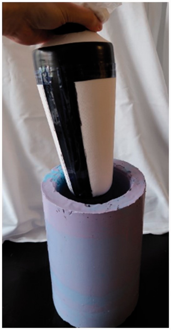
Magnetic composite sheath formation. A coated sheath on a foam positive about to be inserted into the negative mold.
Summary of fabrication process
The final fabrication process, summarized in Appendix 1, started with pulling a sheath over a foam positive for a socket, masking the areas intended to remain free of composite material with PVA, and then curing for 15 min. The exposed areas of the sheath were then coated with unfilled GLYEO and immediately coated again with unfilled polyurethane. The sheath was allowed to cure for 30 min at 50℃. The filled polyurethane layer, which was 75 wt% iron, was then applied to the sheath, which was pressed into a pre-heated negative mold and allowed to cure at 50℃ for 1 h. The positive was removed from the mold and GLYEO/silica coating, containing 38 vol% silica, was applied, dried in the fume hood for 10 min, and allowed to cure for 2 h at 50℃. The sheath was allowed to cure at room temperature for 20 h.
The time devoted to active preparation of the sheaths was approximately 2.5 h; the total elapsed time from start to finish was 25.9 h. A total of about 1.5 h was required to apply the two GLYEO layers, 30 min for the two polyurethane layers, and 25 min to apply the mask to the sheath.
Production of the sheaths required a means to degas the polyurethane. We used an unheated vacuum oven (Model 3606, Lab-Line Instruments, Melrose Park, Illinois) with a vacuum pump (Model 0523, Gast Manufacturing, Benton Harbor, Michigan). While the temperature requirements were low, the exterior dimensions of the mold were larger than many benchtop ovens could accommodate (27 cm tall by 20 cm in diameter) so we used an incubator (Imperial III, Lab-Line) to heat the mold during the curing process. Before curing, GLYEO emits fumes which can irritate the airways and when hydrolyzed it releases ethanol, a flammable gas. Thus, the reaction was carried out in a fume hood.
Target-antenna misalignment testing
We conducted tests to determine to what extent minor sheath misalignment affected sensor results. It is known that conductive targets produce strong signals when the antenna is fully covered by the target material,22 but the performance of magnetic targets was less clear. To test this issue, a 10.0-cm square magnetic target was adhered to the lab bench. An antenna mounted on the testing fixture arm 3.0 mm above the target was moved in horizontal steps across the target while the signal was recorded.
The signal decreased approximately 11% on average from its maximal value when the edges of the target and antenna were even with each other (Figure 7). An 11% signal loss corresponded to a displacement of approximately 0.44 mm.
Figure 7.

Results from testing target antenna misalignment: decay in signal amplitude due to edge proximity. The antenna diameter was 3.2 cm. Based on these results, during clinical use the center of the 32.0-mm diameter antenna was required to be positioned at least 5.1 cm from the target edge. This meant that the target positioned on a liner was required to overlap at least 3.5 cm with the edge of the antenna.
Based on these results, and consideration of the possibility for misalignment of the donned liner, the target positioned on a liner was required to overlap at least 3.5 cm with the edge of the antenna. This specification required the target to be at least 10.2 cm across.
We also tested the tensile stiffness of the composite sheath, using testing procedures developed for evaluation of prosthetic liner materials.23 A mechanical testing machine (5940 load frame, Instron, Norwood, Massachusetts) with a 2000 N load cell was used.
Pressure testing and mechanical property characterization
Because the composite areas were deformable under the loads encountered within a socket, it was important to determine the effect of compression on the recorded signal. Compressive stress was applied using the mechanical testing machine. A custom fixture made of acetal was designed (Figure 8) to insulate the antenna from the metal in the load frame. Pressures up to 250 kPa were applied to a composite sheath sample, while the signal was recorded. A magnitude of 250 kPa was used based on the prior research measuring interface stresses on people with limb loss.24 Since the target did not rest completely flat on the base, an 11 kPa pre-load was applied. The test was replicated at four different antenna-to-target distances: 1.5, 2.5, 4.0, and 4.5 mm. The signal shift was calculated for each pressure by subtracting the frequency ratio with only the pre-load applied from the ratio measured with the pressure applied divided by the pre-load frequency ratio.
Figure 8.

Custom test fixture for characterizing effect of compression on the magnetic composite material. The antenna was placed within a cavity in the base so that only the composite target was compressed.
Compression increased the amplitude of the signal (Figure 9), and the magnitude of the increase was dependent on the target's proximity to the antenna, with smaller distances inducing greater error. However, even at the smaller distances measured (1.5 mm, 2.5 mm), the increase was small, less than 0.12% signal shift at 250 kPa.
Figure 9.

Compression testing results from a magnetic composite sheath with a nylon substrate. Percent signal shift increased with stress and with distance from the target. However, the increases were small.
From material testing machine data, the magnetic composite sheath reduced in thickness to 0.16 mm under a compressive load of 250 kPa. This localized thickness reduction was not expected to have clinical impact during prosthesis use since it is less than the deformation an elastomeric liner experiences during use. The tensile stiffness of the magnetic composite sheath with a nylon substrate was 1.61 MPa.
Field testing on people with limb loss
Participants were included in this study if they had a trans-tibial amputation at least 18 months prior and regularly used a definitive prosthesis at least 4 h per day without assistive aides (e.g. a cane). Candidate participants were excluded if they were currently experiencing skin breakdown or other soft tissue injury. Approval from the University of Washington Institutional Review Board (approval #42899) and written informed consent from participants were obtained before any human subject testing procedures were initiated.
Both participants were male and had their amputations as a result of traumatic injury. Participant characteristics are listed in Table 3.
Table 3.
Participant characteristics.
| Characteristic | Participant #1 | Participant #2 |
|---|---|---|
| Weight (kg)/height (cm) | 94.8/167.7 | 87.0/185.4 |
| Years since amputation | 8.5 | 9.0 |
| Hours prosthesis use/day/K-level | 16.5/3 | 16.0/3 |
| Residual limb (RL) shape | Tapered | Cylindrical |
| RL length (cm)/max circumference (cm) | 14/30.9 | 13.1/30.8 |
| Socket design/liner | PTB/silicone | PTB/TPE |
| Suspension | Locking pin | Locking pin |
| Regular activities | Working out/boxing | Occasional auto repair |
PTB: patellar tendon bearing; TPE: thermoplastic elastomer.
The wear resistance of the sheaths was evaluated by measuring signal strength before and after sheaths were worn by study participants. Signal strength was measured using the following technique. An antenna was sandwiched between a carbon fiber tile and a 1.8-mm thick plastic plate, simulating its condition within a socket. This assembly was affixed to the lab bench. A 44.0-mm thick foam spacer was placed inside the sheath to isolate panels on opposite sides from contacting each other during testing. Measurement points were marked at the lateral and medial sides of the distal and proximal ends of the panels so that positions could be replicated during post-wear tests. For each sensing location on the target (medial distal, lateral distal, medial proximal, lateral proximal on both anterior and posterior surfaces (eight measurement sites total)), a weight was placed on the exposed surface of the composite sheath, inducing a compressive stress of approximately 25 kPa and a measurement was taken for 5 s. The signal mean, for each 5 s measurement, was subtracted from the mean value without weight to calculate signal amplitude. With the initial values recorded, the participant was sent home with the sheath and asked to wear it as part of his or her normal routine. After two to four weeks, the participant returned the sheath to the lab, and the marked locations were retested using the same method.
Results showed signal losses ranging from 0.1% to 1.7%, except for the anterior medial distal site for the four-week test, which was 2.8% (Figure 10).
Figure 10.

Signal loss from field use of the magnetic composite sheath. One participant used the sheath for two weeks and the other for four weeks.
Discussion
Wearable sensors that measure displacements between residual limbs and sockets of prosthesis users must be durable and long lasting to be usable in clinical care. Field data collected over weeks or months may help a patient and prosthetist identify a deteriorating socket fit and the need for modification or replacement. Data from such a wearable sensor might also be used as a feedback signal in automatically controlled adjustable socket systems, which may improve patient outcomes.
Results from the present study demonstrate that the use of ferromagnetic targets, instead of conductive targets as used previously,10 improved performance of inductive sensors for limb–socket displacement measurement. Conductive target performance relies on eddy currents induced on the target surface by current flowing through the sensor's antenna, and thus requires a continuous, defect-free layer of conductive material. Ferromagnetic targets operate on a magnetic permeability principle, thus can be discontinuous, allowing them to take the form of particles suspended within a polymeric matrix, a configuration that is more wear tolerant. The change in oscillation frequency generated by the presence of the iron-seeded composite polymer overwhelmed other magnetic or electric fields, thus the system was not sensitive to the wearer touching metal objects or stray fields in the user's environment.
Chemical strategies helped tackle mechanical bonding and surface texture issues in the present development effort. The base layer of unfilled polyurethane helped to prevent delamination because its lower viscosity allowed it to penetrate and encapsulate the nylon fibers. GLYEO improved adhesion by creating a chemical bond between the nylon and polyurethane. The epoxide groups were able to form bonds with amides in the nylon while the silanol groups, produced by hydrolysis, bound to di-isocyantes in the prepolymer. The opposite NCO groups allowed those bound to GLYEO to be incorporated into the polyurethane matrix. NCO is the chemical formula for an isocyanate functional group in which carbon is double-bonded to nitrogen and oxygen, and nitrogen is also bound to the host molecule. In this case, the molecule was methylbenzene with an additional isocyanate group. GLYEO was also used to create a low-friction surface (on the external surface of the sheath). The silanol groups crosslinked with each other, binding to the di-isocyanates as before, and binding to oxygen atoms on the surface of the silica particles. Compared to both GLYEO and polyurethane, silica was very hard and its presence reduced the polymer's tendency to stick to textured surfaces that the target came in contact with, decreasing its coefficient of friction.
The developed magnetic composite sheaths performed better than conductive targets in field testing. Conductive fabric targets caused at least a 50% signal reduction within two weeks,10 while in the present study less than 3% of the signal was lost over four weeks. We suspect that the reason the anterior distal location in the present study showed the highest signal loss at four weeks was because this site tends to be subjected to high pressures and shear stresses during ambulation,13 which plastically deformed the composite in the sheath, causing areas of local thinning. Additional testing would need to be conducted to determine if the effect worsens under longer wear durations, such as the 6 + month longevity of prosthetic liners.
The tensile stiffness of the magnetic composite sheath did not prove problematic for participants in this investigation in terms of discomfort. However, it is noted that the measured tensile stiffness of 1.61 MPa is higher than that of polyurethane or silicone elastomeric liners commonly used in clinical prosthetics practice, but comparable to that reported for some thermoplastic elastomer liners.25 If they were worn directly on the skin instead of over the outside of the liner, the sheaths may be less comfortable. None of the materials in the sheath, once cured, would be expected to cause chemically induced skin irritation. Potentially, iron particles could be seeded directly into the elastomeric material of the liner during fabrication, possibly reducing the mechanical stiffness issue and improving convenience of the technology. A next step in development of the limb–socket displacement sensor is to conduct clinical trials to determine if deterioration in socket fit metrics preclude deterioration in socket comfort metrics, such as the Socket Comfort Score and subsections of the Prosthesis Evaluation Questionnaire.26,27 If limb–socket displacements proved to be a useful measure of prosthetic fit, then a next step would be to communicate collected data to prosthesis users, via a mobile phone app for example, informing them when a deterioration in socket fit occurred and that accommodation (e.g. sock change or socket size adjustment) was needed. Collected data could also be accumulated and prepared into summary reports for practitioners, augmenting patient self-report at clinical visits.
Acknowledgments
Any opinions, findings, and conclusions or recommendations expressed in this material are those of the authors and do not necessarily reflect the views of the USAMRAA.
Appendix 1
Magnetic composite sheath fabrication process:
Stretch the sheath over a foam positive of a prosthesis user's socket with a PVA bag over it.
Identify areas where composite coating should not be applied, and coat those areas with uncured PVA.
Apply vinyl tape over the PVA coated areas once the PVA has cured, which takes approximately 15 min (the tape and PVA prevent the composite from flowing under the tape).
Coat the nylon or cotton sheath with unfilled GLYEO in the areas where composite is desired (i.e. areas not covered with vinyl tape). This step is not needed for cotton sheaths.
Immediately pour unfilled polyurethane (1.00:0.75 mixing ratio used for all polyurethane) onto the GLYEO-coated sheath and work it into the material.
Place the assembly in the oven for 30 min at 50℃ to let the layers set up.
Apply the iron-filled polyurethane (75 wt%). This is done using a negative mold. The filled polyurethane is applied to the inside of the negative mold and then the positive is forced in and loaded with weights (10.8 kg). This action creates a smooth outer polyurethane surface.
Place the mold in the oven for 60 min at a temperature of 50℃.
Demold the sheath from the negative mold.
Coat the sheath with a 38 vol% fumed silica-filled GLYEO layer (<0.1 mm thickness).
Dry the sheath in the fume hood for 10 min (since ethanol is released while it is drying).
Put the sheath in the oven at 50℃ for 2 h.
Allow the sheath and mold to cure at room temperature for 20 h.
Remove tape; cut PVA bag inside the sheath and remove sheath from positive mold.
Wash away the PVA applied to the sheath with soap and water.
Declaration of conflicting interests
The author(s) declared no potential conflicts of interest with respect to the research, authorship, and/or publication of this article.
Funding
The author(s) disclosed receipt of the following financial support for the research, authorship, and/or publication of this article: This material is based on the work supported by the US Army Medical Research Acquisition Activity (USAMRAA) under Contract No. W81XWH-16-C-0020.
Guarantor
JES
Contributorship
EW designed and fabricated the samples and sheaths, created and conducted bench tests, and carried out participant testing. He helped create and edit the manuscript. JC provided expertise in layup techniques and means to improve viscosity of the uncured composite. BL established clinical requirements for sensor placement, created sensor characterization methods, and assisted with data processing and analysis. KH assisted with bench testing and data analysis. JS created project goals, provided project management, assisted with data analysis, and helped create and edit the manuscript.
References
- 1.Grevsten S, Eriksson U. Stump-socket contact and skeletal displacement in a suction patellar-tendon bearing prosthesis. J Bone Joint Surg 1974; 56: 1692–1696. [PubMed] [Google Scholar]
- 2.Grevsten S. Ideas on the suspension of the below-knee prosthesis. Prosthet Orthot Int 1978; 2: 3–7. [DOI] [PubMed] [Google Scholar]
- 3.Commean PK, Smith KE, Vannier MW. Lower extremity residual limb slippage within the prosthesis. Arch Phys Med Rehabil 1997; 78: 476–485. [DOI] [PubMed] [Google Scholar]
- 4.Fernie G, Holliday P. Volume fluctuations in the residual limbs of lower limb amputees. Arch Phys Med Rehabil 1982; 63: 162–165. [PubMed] [Google Scholar]
- 5.Hafner BJ, Sanders JE. Considerations for development of sensing and monitoring tools to facilitate treatment and care of persons with lower-limb loss: a review. J Rehabil Res Dev 2014; 51: 1–14. [DOI] [PMC free article] [PubMed] [Google Scholar]
- 6.Sanders JE, Karchin A, Fergason JR, et al. A noncontact sensor for measurement of distal residual-limb position during walking. J Rehabil Res Dev 2006; 43: 509–516. [DOI] [PubMed] [Google Scholar]
- 7.Gerschutz MJ, Hayne ML, Colvin JM, et al. Dynamic effectiveness evaluation of elevated vacuum suspension. J Prosthet Orthot 2015; 27: 161–165. [Google Scholar]
- 8.Board WJ, Street GM, Caspers C. A comparison of trans-tibial amputee suction and vacuum socket conditions. Prosthet Orthot Int 2001; 25: 202–209. [DOI] [PubMed] [Google Scholar]
- 9.Swanson EC, McLean JB, Allyn KJ, et al. Instrumented socket inserts for sensing interaction at the limb-socket interface. Med Eng Phys 2018; 51: 111–118. [DOI] [PMC free article] [PubMed] [Google Scholar]
- 10.Sanders JE, Redd CB, Larsen BG, et al. A novel method for assessing prosthesis use and accommodation practices of people with trans-tibial amputation. J Prosthet Orthot 2018. [DOI] [PMC free article] [PubMed] [Google Scholar]
- 11.Thyssen JP, Linneberg A, Menné T, et al. The epidemiology of contact allergy in the general population – prevalence and main findings. Contact Dermatitis 2007; 57: 287–299. [DOI] [PubMed] [Google Scholar]
- 12.Baer RL. Allergic contact sensitization to iron. J Allergy Clin Immunol 1973; 51: 35–38. [DOI] [PubMed] [Google Scholar]
- 13.Cordova CW and Rowan HH. Polyamide fiber reinforcement in thermoset polyurethane composites. US Patent No. 4,695,509, USA, 22 September 1987.
- 14.Karakoy M, Gultepe E, Pandey S, et al. Silane surface modification for improved bioadhesion of esophageal stents. Appl Surf Sci 2014; 311: 684–689. [DOI] [PMC free article] [PubMed] [Google Scholar]
- 15.Metzler S, Zankovych S, Rauchfuß F, et al. In vitro analysis of biopolymer coating with glycidoxypropyltrimethoxysilane on hernia meshes. J Biomed Mater Res Part B Appl Biomater 2017; 105: 1083–1090. [DOI] [PubMed] [Google Scholar]
- 16.Ogden S, Lewis D, Shapter J. Silane Functionalisation of Iron Oxide Nanoparticles. In: Proceedings of SPIE – The International Society for Optical Engineering 2008. 1;7267: 72670A–1–72670A–11.
- 17.Caldara M, Colleoni C, Guido E, et al. Optical monitoring of sweat pH by a textile fabric wearable sensor based on covalently bonded litmus-3-glycidoxypropyltrimethoxysilane coating. Sens Actuators B Chem 2016; 222: 213–220. [Google Scholar]
- 18.Guo R, Du X, Zhang R, et al. Bioadhesive film formed from a novel organic–inorganic hybrid gel for transdermal drug delivery system. Eur J Pharm Biopharm 2011; 79: 574–583. [DOI] [PubMed] [Google Scholar]
- 19.Wypych G. 2.151.1 Fumed silica. In: Handbook of fillers. 2nd ed. New York: Plastics Design Library, 2000.
- 20.Sanders JE, Zachariah SG, Jacobsen AK, et al. Changes in interface pressures and shear stresses over time on trans-tibial amputee subjects ambulating with prosthetic limbs: comparison of diurnal and six-month differences. J Biomech 2005; 38: 1566–1573. [DOI] [PubMed] [Google Scholar]
- 21.Razak AHA, Zayegh A, Begg RK, et al. Foot plantar pressure measurement system: a review. Sensors (Basel) 2012; 12: 9884–9912. [DOI] [PMC free article] [PubMed] [Google Scholar]
- 22.Oberhauser C. LDC sensor design. Texas Instruments, 2015, www.ti.com/lit/snoa930 (2015, accessed 22 February 2018).
- 23.Cagle JC, Reinhall PG, Hafner BJ, et al. Development of standardized material testing protocols for prosthetic liners. J Biomech Eng 2017; 139: 045001–1–045001–12. [DOI] [PMC free article] [PubMed] [Google Scholar]
- 24.Sanders JE, Lam D, Dralle AJ, et al. Interface pressures and shear stresses at thirteen socket sites on two persons with transtibial amputation. J Rehabil Res Dev 1997; 34: 19–43. [PubMed] [Google Scholar]
- 25.Cagle JC, Hafner BJ, Taflin N, et al. Characterization of prosthetic liner product for people with trans-tibial amputation. J Prosthet Orthot 2018. [DOI] [PMC free article] [PubMed] [Google Scholar]
- 26.Hanspal RS, Fisher K, Nieveen R. Prosthetic socket fit comfort score. Disabil Rehabil 2003; 25: 1278–1280. [DOI] [PubMed] [Google Scholar]
- 27.Legro MW, Reiber GD, Smith DG, et al. Prosthesis evaluation questionnaire for person with lower limb amputations: assessing prosthesis-related quality of life. Arch Phys Med Rehabil 1998; 79: 931–938. [DOI] [PubMed] [Google Scholar]