

Abstract
The haptic sense relies upon a plurality of receptors and pathways to produce a complex perceptual experience of contact, pressure, taps, vibrations and flutters. This complexity is yet to be reproduced in haptic feedback interfaces that are used by people controlling a dexterous robotic hand, be it for limb-absence or teleoperation. The goal of the present bimodal haptic armband is to convey both low-frequency pressure changes and high-frequency vibrations from a dexterous robotic hand to a human’s upper arm, so as to guide his/her control of the artificial limb. To that end, we design and manufacture four novel soft robotic armbands combining inflatable air chambers and vibrotactile stimulators. We develop control systems for both pathways. We conduct a series of benchtop tests to determine the pneumatic and vibrotactile performance and select from competing designs and materials. We test two of the resulting bimodal haptic armband on human subjects and confirm their ability to use both aspects of this haptic information. Arguing that dexterous artificial hands are presently not used to their fullest capability by the dearth of haptic information in users, this work aims to achieve a more realistic tactile experience for a fluent, more natural usage of robotic artificial hands.
I. Introduction
Dexterous robotic limbs employed for functional remediation of amputation and congenital limb-absence need to be controlled in real time in a fluid manner. Exceptional recent developments in robotic limbs’ mechanical abilities find a very stark bottleneck in the human capacity for online control. Without the haptic perception of the contact between robotic hand and the objects that it manipulates, and without feeling the conformation of different joints and limb segments, real-time control of purpose-oriented robotic hand movement is much harder [1], [2], [3], [4], [5]. Furthermore, this sensory return on robotic hand movement restores the integrity of the efferent-afferent loop that is central to human behavior [6], [7] allowing for embodiment of the artificial limb [1], [3], [8], [9] and offering enhanced satisfaction for users [4], [9], [10] including the experience of affective touch [3], [11], [12] that is paramount for a fulfilling life of interacting with others.
Among the noninvasive interfaces that are used to return the haptic experience to people controlling a robotic arm and hand are a variety of pneumatic/hydraulic, electrotactile or vibrotactile actuators and thermoelectrical devices whose stimulation is relocated to other body parts such as the face, arm, residual limb, back or chest [5], [13]. In the following, we develop a novel bimodal soft pneumatic and vibrotactile haptic armband whose end goal is to combine information about low-frequency pressure dynamics and vibrotactile sensations related not only to sliding contact but also the direction of slip.
The goal of this paper is evaluating the efficacy of the novel soft robotic armband. We outline the novel soft robotic armband design and manufacturing (section II). Next, the impact of four independent variables on the soft robotic armband performance is tested in benchtop experiments (section III). From the results of these tests, a nonlinear controller is designed (Section IV) and two different armbands are selected for human subject testing in a psychophysics study (Section V). Conclusions and future work are discussed in section VI.
II. BiModal Haptic Armband Development
Natural haptic sense is created from a number of specialized tactile receptors [16] whose individual stimulation evokes different sensations such as flutter, vibration, pressure or tapping [17], [18] and whose functional significance is only imperfectly understood [19]. Models have proposed that the four principal haptic receptors, Merkel, Meissner, Pacinian and Ruffini, carry distinct information about object contact, motion, direction, texture, form, pressure and skin deformation, to name a few functional concepts. After an era when haptic devices only modeled one aspect of this complex sensory experience, efforts have more recently emerged to create systems carrying multiple informational channels on the relationship between hand motion and the objects and surfaces it interacts with [14], [15], [20], [21], [22].
Accordingly, the present study utilized a novel bimodal haptic armband to apply (1) slowly adapting pressures related to steady state robotic fingertip forces and (2) rapidly adapting vibratory fingertip sensations to the upper arm of the wearer. Ultimately, this armband (Fig. 1(E)) will be used during real-time control of an artificial hand with high-density BioTac tactile sensors (Syntouch, Los Angeles, USA) mounted on the fingertips of a Dexterous Shadow Hand (Shadow Robot Company, London, UK), (Fig. 1(C)) to refer tactile sensations elicited during robotic hand grasps to the residual limb of people who have a congenital or attained upper limb absence.
Fig. 1.

Overview of the bimodal haptic actuator embedded in a close-loop system, with a subject (A) controlling the robotic hand (B-C), eliciting tactile information in the course of its interaction with objects and surfaces; information that is returned by the haptic controller (D) to a bimodal haptic actuator (E) wrapped around the subject’s arm.
In its final form, the armband aims to create well-mapped sensations of pressure and both high and low-frequency sensation of vibration to the subject, in order to minimize his/her mental load while controlling an artificial hand. To advance toward this goal, we explore the effect of 4 factors in the bimodal haptic armband: 2 designs of the soft pneumatic actuators (D1, D2, henceforth); 2 types of air pumps supplying air to inflate the soft actuators; 2 levels of material Shore hardness of a rubber material used to construct the pneumatic actuators (Ecoflex 30 and Ecoflex 50, (Smooth-On, PA)) and 2 densities of vibrotactile stimulators (3 or 5 stimulators per armband).
A. Design of Bimodal Haptic Armband
SolidWorks (Trimech, VA) was used to design two armband prototypes, D1 and D2 so that molds could be 3D printed. Both armband designs could be readily integrated within the sockets of prosthetic limbs for a seamless feedback channel of tactile information to limb-absent people during tasks of daily life. Both designs have the same inlet nozzle to standardize the pneumatic input into the actuator. D1 and D2 both had hemispherical air chambers with diameters of 1.5cm and 0.36cm, respectively. D2 was theorized to have a faster response time than D1 for equal pressures since a smaller volume needed to be pressurized.
A two-step molding process was used to make the armbands, in which the two layers were independently molded before being bonded together. The two layers were molded from two ISO 10993–10 certified skin-safe materials of different Shore hardness. The foundation is molded from Dragon-Skin 30 (Smooth-On, PA), a relatively rigid rubber compared to either of the two rubbers used for the actuation layer, Ecoflex 30 or Ecoflex 50. These were chosen to be elastic enough to allow for expansion of the air chambers when inflating, without persistent deformation.
B. Armband Manufacturing
The armband was made of flexible, silicone rubbers to accommodate human arms of varying morphologies with minimal discomfort. Three 3D printed parts were made to act as molds and insert (Fig. 2(A)). The insert is sealed to the actuation layer mold with hot glue so that the internal geometry of the armband will be formed (Fig. 2(B)). Two variations of the foundation layer were fabricated, one with three vibrotactile stimulators (Vibrating Mini Motor Disc at 5V, Adafruit), (Fig. 2(F)) and another with five. Depending on the number of vibrotactile stimulators being used, they are placed in either every spotface or every other spotface of the mold (Fig. 2(C)). These vibrotactile stimulators were responsible for the high-frequency tactile sensations that the subject experienced during this psychophysics study discussed subsequently. The electrical wires used to power each vibrotactile stimulator exited the foundation layer through rectangular tabs which provided strain relief for the solder joints. Next, the respective rubbers were degassed in a vacuum chamber before filling the molds (Fig. 2(D)). After each layer fully cured, the actuation layer was removed from its mold as one piece (Fig. 2(E)). The actuation layer was subsequently fused to the foundation layer with additional EcoFlex (Fig. 2(F)). The more rigid foundation acts as a strain limiter, constraining the air bladders to expand normally to the armband (Fig. 3, (C-F)), creating a clear percept of pressure on the skin when the armband is worn by subjects.
Fig. 2.
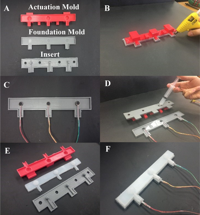
(A) The molds and the insert are 3D printed. (B) The actuation layer mold and the insert are sealed together with hot glue. (C) Vibrotactile stimulators are placed in the spotfaces of the foundation mold. (D) The respective liquid rubbers fill the foundation and actuation layer molds. (E) Actuation layer is removed from its mold. (F) The two layers are fused together with additional EcoFlex.
Fig. 3.

Variations in the design of the bimodal haptic actuator. (A) Armbands with two geometries D1 and D2 for the air chambers. (B) Two pump models resulting in different pneumatic profiles: (C,D) Design-1 uninflated, and inflated, (E,F) Design-2 uninflated, and inflated.
The fully fabricated armbands had three soft robotic actuators separated by 7.2cm spaces (Fig. 3(A)), a separation that exceeds the spatial discrimination threshold of the upper arm [19], [23], [24]. To inflate the soft actuators, air pumps (Pump 1 or Pump 2 from Fig. 3(B)) were connected to each air chamber via rubber tubing (0.3175cm diameter) and secured to each of the tabs via a zip tie.
III. Bimodal Haptic Armband Benchtop Testing
In the following, benchtop experiments were conducted for the soft actuators and the vibrotactile stimulators prior to human subject testing.
A. Testing the Soft Pneumatic Actuators
To test the pneumatic actuators, both air chamber and valve were connected to either pump 1 (Mini Air Pump DIMINUS, China) or pump 2 (D220S-V, TCS Micropumps Ltd, UK) (Fig. 3(B)). Each of the four armband designs (D1 and D2, with EcoFlex 30 or 50) were sequentially placed on a benchtop so that one of the soft actuators contacted a 2kg load cell (LSP-2, Transducer Techniques, Temecula, USA) to record the applied force (FSA) of the soft actuator. The internal pressure (PSA) of the air chambers was simultaneously measured with a 103 KPa pressure sensor from Honeywell. Each pump was driven open loop with a ½ Hz square wave using Simulink which was published to Robot Operating System (ROS) using the ROS toolbox. This topic was subscribed to with Arduino Uno to drive the pump with the PWM motor driver ((Pololu 0J7303 Pololu Corporation, LV). These benchtop tests resulted in three independent variables: (1) soft actuator material Shore hardness: 30 or 50, (2) air chamber geometric design: D1 or D2 (Fig. 3(C-F), (3) air pump model Pump 1 or Pump 2 (Fig. 3(B)).
The actuators were inflated/deflated 15 times for all eight combinations of three independent variables. The first five cycles were trimmed to allow the system to reach steady state and the next ten cycles were analyzed for the maximum force and pressures that each of the eight combinations of the three independent variables produced. Data were sampled at 1 KHz.
B. Results from the Soft Actuator Benchtop Tests
Sample data show time series for the applied air pressure (PSA) and measured force (FSA) at the soft actuators (Fig. 4). The aggregated results of this test shows the correlation between the maximum forces and pressures for each of the two designs (D1 and D2), (Fig. 3(A)), pumps (P1 and P2), (Fig. 3(B)), and materials (Ecoflex 30 and Ecoflex 50), (Fig. 5). From these tests, it is clear that Pump 1 generally enabled larger forces and pressures. Second, we observe that EcoFlex 30 permitted larger forces for fairly comparable internal pressure levels. Third, D2 was unable to deliver as much force as D1 even though the applied pressure (x-axis) was almost the same. Because the upper-arm of humans has a lesser concentration of tactile receptors and smaller acuity/larger detection threshold [23], [24], a smaller force likely deteriorates the subject’s ability to perceive haptic events. Therefore, the geometry of Design 1 is selected for future tests with human subjects and Design 2 withdrawn. Even though EcoFlex 30 enabled higher forces for comparable pressures, Ecoflex 50 was retained for comparative studies with human subjects. The rationale for this is that even though EcoFlex 30 is preferred from a force resolution viewpoint, the higher Shore hardness of EcoFlex 50 could provide a more robust, longer lasting device more capable of withstanding the rigors of daily life.
Fig. 4.

Illustrative data from four combinations of pump (Pump 1 or 2), geometric design (D1 or D2), and actuator material (EcoFlex 30 or 50).
Fig. 5.

Input/output relationship between internal actuator air pressure (PSA) and force recorded at the loadcell from the pneumatic actuator (FSA).
C. Hysteresis Between Soft Actuator Internal Pressure (PSA) and External Applied Force (FSA)
In another test, we explored in more detail (1) nonlinearities in the haptic response of the soft actuators (EcoFkex 30 and 50) to air pressures applied by the pump; and (2) hysteresis in the inflation and deflation process for a series of four different internally applied pressures. For each pressure level, twenty cycles for inflation and deflation (ten each) was recorded to study the effect of hysteresis. The resulting effect was also assessed by measuring the applied force by the soft actuator on a load cell (Fig. 6). Like before, Ecoflex 50 intakes larger air pressures and restitutes smaller forces by the soft actuator, especially for larger internal pressures. Importantly, only a modest amount of hysteresis was observed: for each trajectory, inflation slightly diverges from deflation. But overall, the ascending and descending phase remain very close. Studying the four internal loads for a given material, we observe that their trajectories are consistent: their ascending phase is indistinguishable, and their descending phase exhibits only minor variations across internal pressures. Minimal hysteresis is desirable: as mentioned before, chosen materials should undergo minimal permanent deformation. From a study of the benchtop data above, we also estimate the nonlinear relationship between applied air pressure and force generated at the soft actuator. Since this relationship has a minimal load dependency and a modest hysteresis, it can be modeled with a third order polynomial (Eqs. 1 and 2), separately for each material (Ecoflex 30 and Ecoflex 50).
Fig. 6.

Hysteresis Curves for EcoFlex-30 and EcoFlex-50 Arm Bands with different loads applied. See details in text.
| (1) |
| (2) |
D. Time-Frequency Analysis of the Vibrotactile Stimulator
In a final test, we explore the frequency response of the vibrotactile stimulators. For testing purposes, a BioTac SP was instrumentalized because it is able to precisely record pressure signals at fast sampling rates. For this test, the vibrotactile stimulator was placed in contact with a BioTac SP (Fig. 7(A)) to measure its mechanical vibrations (Fig. 7(B)). The vibrotactile stimulation signal (V1) was created in Simulink using the ROS toolbox and fed to ROS. Arduino Uno was used to subscribe to the topic input from Simulink and a Pulse Width Modulation (PWM) signal was output to the vibrotactile stimulator. In this test, the duty cycle of the PWM was 50% and sampling frequency was 1KHz.
Fig. 7.

Time-Frequency response of the Vibrotactile Stimulator contacting a biomimetic tactile array (Biotac SP), (A) Vibrotactile Stimulator contacting a Biotac SP. (B) The time series recorded by Biotac, (C) Time-Frequency-Power plot, (E) Color legend, and (D) Spectrograms comparing ON and OFF periods.
A representative signal measured by a BioTac at dynamic pressure modality (Fig. 7(B), its time-frequency response (Fig. 7(C), see legend in Fig. 7(E)) was derived from a Continuous Wavelet Transform with a Complex Morlet wavelet in MATLAB and a comparison was made between the spectrograms observed when the vibrotactile stimulus was ON and OFF (Fig. 7(D)). Distinct peaks were observed at 22 and 84Hz superimposed on a 1/f distribution, reflecting the interaction of the vibrotactile stimulator with the BioTac SP. The frequency distribution of those two peaks is consistent for the duration of the stimulation and across cycles (with slightly more variability for the 84Hz peak than for the 22Hz peak, not shown), and suggest an adequate recruitment of the tactile receptors specialized for high-frequency vibrations, which are especially relevant for the slippage of insecurely grasped objects and tactile sensations arising from the exploration of surfaces and textures.
IV. Design of the Controller
Based on the benchtop results presented in Section III, a nonlinear controller was developed for the soft actuators and vibrotactile stimulators. The two duties of the haptic feedback controller are first to transform inputs from the BioTac SP sensors fitted on the fingers of the dexterous robotic hand, the Shadow Hand (Fig. 8(A)) into pneumatic and vibrotactile signals within the armband, that is, to control airflow into and out of the soft actuators (Fig. 8(B, D)); and (2) to input power into the vibrotactile stimulators (Fig. 8(C, D)). To that end, the steady state fingertip pressure (PDC from the BioTac) was used to control the internal pressure of the corresponding soft actuator (PSA). The high-frequency fingertip force (PAC), which is the filtered derivative of PDC, was used to control the vibrotactile stimulator, as will be subsequently described.
Fig. 8.

Bimodal haptic armband controller. (A) BioTac SP on the tip of Shadow Hand. (B) Soft Actuator Pressure Controller. (C) Dynamic Pressure Modality (PAC) Controller. (D) Bimodel Armband Output.
A. Nonlinear Pressure Controller for Soft Actuators
A closed-loop system was developed to control the air pressure applied within the soft actuator (Fig. 8). The goal of this controller is to make the BioTac fingertip pressure (PDC) match the applied pressure within the soft actuator (PSA). Ideally, a linear relationship would exist between tactile pressure experienced by the BioTac on the artificial hand and the output pressure experienced by the subject at the site of soft actuators around the armband. However, due to hysteresis and nonlinear armband material dynamics (Fig. 6), this was not the case. Thus, a nonlinear pressure controller was developed for the pump and valve of each soft actuator to minimize the error (e) between the robotic fingertip pressure (PDC) and the soft actuator pressure (PSA), (Fig. 8(B)).
Arduino Uno was used to control the pump’s motor driver to activate airflow and a 12V 2-way valve (TCS Micropumps Ltd) was used to direct air flow either into the soft actuator for inflation or into the environment for deflation. Valve chatter was minimized using empirically determined deadbands. To aggressively minimize the error signal, a saturation function was used to enable high gains and rapid system response with a bounded control signal. The error control signal (e) is formed to control the pump and valve as per Eqs. (3, 4, 5, and 6).
| (3) |
| (4) |
| (5) |
| (6) |
Here, uP and uv are the pump and valve control signals respectively, Kp is the proportional gain, e is the error signal, PDC is the robotic fingertip pressure measured by the BioTac, PSA is the soft actuator pressure, H is the deadband upper limit, and L is the deadband lower limit. Without the deadband, solenoid valve chatter was audibly distracting.
Sample data of this control system is shown in Fig. 9. Here, a BioTac pressure sensor on the first finger of the Shadow Hand was manually squeezed three times (Fig. 9(A), blue). This fingertip pressure (PDC) was then used as the input to the controller (Fig. 8(B)) to inflate the soft robotic actuator so that the internal pressure of the soft actuator (PSA) closely matched the BioTac fingertip pressure (Fig. 9(A), red). The force of the soft actuator (FSA, Fig. 9(B), blue) was also measured with the load cell, which is closely correlated to the internal pressure (PSA, Fig. 9(A), blue). It is clear that opening the normally closed valve (Fig. 9(B), red) led to deflation and decreases in force (Fig. 9(B), blue).
Fig. 9.

(A) Exemplary time series showing how the System Pressure (PSA) follows input signal PDC from a BioTac sensor array. (B) The force of the soft actuator (FSA) increased in tandem with the internal pressure. The valve signal uv (red) shows that the valve was opened when the error was below the deadband threshold L, prompting a deflation and a decrease in the force (FSA) when the valve was opened. (C) PAC from the first finger (FF) was used to drive the vibrotactile stimulator placed on the little finger (LF). (D) Photo showing the experimental setup to obtain the data in parts (A) – (C).
B. Controller for Vibrotactile Signaling of Sliding Motion
The first goal of the vibrotactile controller (Fig. 8(C)) is to make the high-frequency signal (PAC) from the robotic fingertip to be very similar to the vibrotactile sensations on the arm of the test subject via the armband. To study this relationship, two BioTac sensors and a vibrotactile stimulator were used. One BioTac sensor on the index finger provided the high-frequency signal to the vibrotactile stimulator that was placed atop the observational BioTac sensor on the little finger of the Shadow Hand (Fig. 9(D)). The second, observational BioTac is a surrogate sensor array capturing the high-frequency haptic signal that a human upper arm would experience when the bimodal haptic armband is worn (that is, like in Fig. 7(A), a BioTac is instrumentalized as a high-precision, high sampling tactile sensor). This test was run simultaneously with that from the soft actuators (Fig. 9(A-B)), and the originating haptic events were the same three manual applications of force. As expected, there is a close correlation between PAC on the first finger (FF) and the PAC measured on the little finger (LF), (Fig. 9(C)).
The second function of this controller concerns the sequential order of activation for the 3 or 5 vibrotactile stimulators. For future real-time control experiments, an Artificial Neural Network (ANN) will be built into the controller and used to detect and classify the direction of sliding contact [25]. When a sliding contact or slip occurs with the dexterous artificial hand in one direction, the controller will sequentially trigger successive vibrotactile stimulations in adjacent stimulators in a clockwise manner, radially around the circumference of the limb outfitted with the haptic armband. The counterclockwise direction will be used for sliding contact in the opposite direction (Fig. 10).
Fig. 10.

Vibrotactile stimulators cured into the base layer (A) were powered in succession to elicit a percept of moving vibration around the arm in either a clockwise or a counterclockwise direction. (B) an example temporal sequences for 5 Stimulators.
V. Human Psychophysics Assessment
In the following, we have retained the best design and pump (D1 and Pump 1) after examination of the benchtop results of Section III, and we test the armband with limb-intact human subjects, to assess the ability of the bimodal haptic interface to transfer two kinds of information to them: (1) the applied grasp force and (2) the direction of sliding contact between the hand and grasped objects.
To those ends, 10 participants were recruited between the ages of 20 and 30 years (8 males and 2 females). The protocol was approved by the Internal Review Board of Florida Atlantic University and agreed with the declaration of Helsinki. All subjects gave a written informed consent.
A. Methods
1). Human Perception of Force from Soft Actuators
First, we examined human haptic perception with the two soft robotic armbands made from EcoFlex 30 and 50. Six different soft actuator pressure levels were tested with each of these armbands to evaluate the ability of the people to distinguish between different amplitudes of grasp force that were mapped to their upper arms. Before the experiment, the armband was placed atop the upper right arm of the subjects in a standardized position (Fig. 1) and secured in place with a flexible elbow support brace (BRACCO S.p.A., Milan, Italy). Next, the human subjects were trained to recognize six air pressure levels (PSA = 10, 15, 20, 25, 30, and 35 KPa). These values translate into haptic forces (see Fig. 6) that exceed the just noticeable differences found by [24] and we hypothesize that subjects are able to discriminate between them.
In the training session, each of the six pressure levels was applied repeatedly five times and the subjects were informed each time what the pressure level was. At the end of the training session, each pressure level was applied once more to remind the test subject what each pressure level feels like. During the experiment, 30 trials of a pseudo-random sequence of pressure levels were applied for each test subject; all the subjects were tested with the same sequences with all six pressure levels presented five times each. In all cases, the applied pressure was maintained for 10 seconds to give enough time to feel the pressure level. Once each trial was completed, subjects identified their perception of the pressure level on a scale of 1–6. Statistical analysis was performed on the accuracy of the two human subject trials using the MATLAB function ‘anova2’, for analysis of variance of two variables: the six pressure levels and the two armband materials were the two independent variables, and the accuracy of correctly identifying the pressure level was the dependent variable.
2). Human Detection of Sliding Motion Direction
A second test assessed the subjects’ ability to perceive the direction of motion in the serial array of vibrotactile stimulators. The same ten test subjects participated on a different day to prevent fatigue from influencing results. In these tests, the armband was placed on the same location and orientation as the pressure test. Nine different vibration durations were tested to determine the minimum time required for people to perceive and interpret correctly the direction of sliding contact. A minimal time is desirable because delays at the human-robot control interface needlessly destabilizes grasp control capabilities, leading to undesirable dropping of objects. The test was conducted with either 3 or 5 stimulators; the rationale for this is that three stimulators can more quickly convey a sense of slip direction than five if the stimulation duration is equal within each vibrotactile stimulator. The protocol was designed to trigger the high-frequency stimulators sequentially in clockwise or counterclockwise directions radially around the forearm outfitted with the armband (Fig. 10), (correlated to different directions in the robotic hand coordinate frame) with nine different stimulation durations (20, 40, 60, 80, 100, 125, 150, 175, 200 ms). The test subjects were initially trained five times with each of these nine stimulation durations for both clockwise and counterclockwise directions of travel. In the testing part, 50 pseudo-random sequences were used with all test subjects. After each trial, the subjects’ perceived direction of slip was entered in an Excel file for future analysis. The same armband was used for both the cases of 3 or 5 vibrotactile stimulators (Fig. 10).
A two-factor statistical test was performed again with the anova2 function in MATLAB. The independent variables were the vibration durations and the two amounts of vibrotactile stimulators (3 or 5), and the accuracy of correctly identifying the direction (clockwise, counterclockwise) as the dependent variable.
B. Results
1). Human Perception of Force from Soft Actuators
The ability of the subjects to distinguish between the six different applied pressure levels from the two-different soft robotic armbands are expressed as confusion matrices for the EcoFlex 30 (Fig. 11(A)) and EcoFlex 50 (Fig. 11(B)) materials. Each cell in the confusion matrix represents a percentage of the responses from the human subjects for each individual pressure level. Overall, perceived pressure levels (vertical axes of Fig. 11) progressed for increasing levels of actual pressure (horizontal axes). Pressure level 1, the lowest, had the most accurate percentages, perhaps in part because it was close to or below the perceptual threshold: so, if the subjects did not feel any pressure sensation, they possibly took the strategy to report it as pressure level 1. For both soft actuators with Ecoflex 30 and 50, human perception of pressure was often one level below the actual pressure level. Human subjects were also able to correctly identify pressure level 5 and 6 with a higher accuracy than pressure levels 2–4. As for a comparison between the armband materials, with Ecoflex 50 (Fig. 11(B)), subjects were more accurate at perceiving the lower pressure, and with Ecoflex 30 (Fig. 11(A)), better performance was observed for the higher-pressure levels. Overall, these results suggest that subjects were able to use the force information provided at their upper arm to order their perceived haptic experience.
Fig. 11.

Armbands Perceived Pressure vs Actual Pressure for the armbands made from (A) EcoFlex-30 and (B) EcoFlex-50.
ANOVA results of these experiments show that the two armband materials did not have a significant impact (p > 0.05) on the subjects’ performances, while the soft actuator pressure (PSA) applied had a significant impact (p < 0.01) on the performance. Interaction effects were not significant (p> 0.05). This supports the data showing that the subjects were more accurately able to identify the armband pressure at low and high pressures, regardless of the armband material.
2). Human Detection of Sliding Motion Direction
Finally, we studied the ability of subjects to determine if the sequentially actuated vibrotactile array was activated in a clockwise or counterclockwise direction. The mean and standard deviation of the human subjects’ responses are shown in Fig. 12. The trials with a time delay from 100 – 200 ms were detected with almost 100% accuracy. With 20 ms time delay, human subjects were basically unable to feel any vibration for either 3 or 5 vibrotactile stimulators and opted to not make a choice, which was counted as a failure. For the time delays between 40 and 80 ms, the human subjects’ performances increased. Over this interval, subjects were also able to feel the direction of slip with 5 vibrotactile stimulators more accurately than with 3 stimulators, on average.
Fig. 12.

Means and standard deviations from the test subjects identifying the direction of slip for different vibratory activation durations.
However, analysis of the sliding contact direction trials shows that the number of vibrotactile stimulators did not have a significant impact (p > 0.05) on the subjects’ performances, while delay time had a significant impact (p < 0.01) on the performance. Similar to the other trial, the two variables did not have a significant interaction (p > 0.05). This supports the data showing that the subjects were able to more accurately identify the direction at large time delays compared to small time delays.
Those results suggest that the vibrotactile array would reach the best compromise between accuracy and duration with 3 vibrotactile stimulators signalling slips over durations of 100 ms for each vibrotactile stimulator (for a total stimulation time of 400 ms). With longer stimulation durations, there is little gain in accuracy due to the ceiling effect: performance saturates above 100 ms vibration durations.
VI. Conclusion
Our aim was to develop a bimodal haptic armband with pneumatic and vibrotactile actuators to wear on the upper arm. The armband conveys two distinct information streams about pressure changes and directional, slip-elicited high-frequency vibrations and therefore proposes a haptic interface that more closely approaches the complexity of a real hand’s haptic communication channels. The armband is driven by high-density BioTac SP sensors placed installed on the fingers of a dexterous robotic hand to inform the operator about haptic events experienced while manipulating objects or exploring surfaces (Fig. 1).
After developing prototype armbands and controllers, we have tested a variety of geometric designs for the air chambers, combinations of pump and material of the pneumatic actuator (Fig. 3), and for the spatial density and temporal property of a sequentially actuated vibrotactile stimulation signal (Fig. 10). We conducted both benchtop testing and experimental investigation with ten limb-intact subjects. We have found that an air chamber with comparatively larger volume, driven by a larger pump provided the most helpful basis to bring the pneumatic haptic feedback in the range of human perception (Fig. 5). Another analysis revealed a modest hysteresis for the two candidate materials for the pneumatic chambers. We also found that subjects fitted with the armband could recognize pressure levels applied in the pneumatic actuators reasonably well, with a better discrimination at low pressure for the material Ecoflex 50 (Fig. 11(B)), and a better performance at high pressure for Ecoflex 30 (Fig. 11(A)).
On the side of the high-frequency vibrotactile actuator, we determined the time-frequency profile of the stimulators as peaking in the 22 and 84Hz frequency ranges (Fig. 7). We investigated subjects’ abilities to detect the direction of motion in 3 or 5 sequentially-activated vibrotactile actuators. As mentioned above, the less the time delay to convey information about slips, the most efficient the haptic feedback. According to the results collected from our experiment (Fig. 12), the best stimulation duration would be between 80 and 100 ms per vibrotactile stimulator. Since 5 vibrotactile stimulators would take more time to finish the cycle and since both 3 and 5 vibrotactile stimulators are close in the accuracy for (80,100) ms, 3 vibrotactile stimulators armband would be the best candidate for control of an artificial hand.
In future stages of this research, we plan to integrate the armband with a direction of slip detection algorithm [25]; incorporate an algorithm for correction of the nonlinear relationship between applied air pressure and tactile sensation; conduct further psychophysics experiments in context of dual tasks developed to use simultaneously the information from the vibrotactile and pneumatic stimulators; before moving the haptic interface into life-like tests of grasp control with a dexterous artificial hand [26], [27].
Acknowledgments
* This research was supported in part by NIH 1R01EB025819 and NSF awards 1317952, 1536136, and 1659484, NIBIB award # 1R01EB025819 and by I-SENSE at FAU
Contributor Information
Michael Bornstein, Ocean and Mechanical Engineering Department, Florida Atlantic University, Boca Raton, FL 33431 USA..
Emmanuelle Tognoli, The Center for Complex Systems and Brain Sciences, Florida Atlantic University, Boca Raton, FL 33431 USA..
Erik D. Engeberg, Ocean and Mechanical Engineering Department, Florida Atlantic University, Boca Raton, FL 33431 USA.
References
- [1].Rosén B, Ehrsson HH, Antfolk C, Cipriani C, Sebelius F, and Lundborg G, “Referral of sensation to an advanced humanoid robotic hand prosthesis,” Scand. J. Plast. Reconstr. Surg. Hand Surg, vol. 43, no. 5, pp. 260–266, 2009. [DOI] [PubMed] [Google Scholar]
- [2].Kwok R, “Once more, with feeling,” Nature, vol. 497, no. 9 May, p. 176, 2013. [DOI] [PubMed] [Google Scholar]
- [3].Ackerley R and Kavounoudias A, “The role of tactile afference in shaping motor behaviour and implications for prosthetic innovation,” Neuropsychologia, vol. 79, pp. 192–205, 2015. [DOI] [PubMed] [Google Scholar]
- [4].Jette AM, “The promise of assistive technology to enhance work participation,” Physical Therapy, vol. 97, no. 7, pp. 691–692, 2017. [DOI] [PubMed] [Google Scholar]
- [5].von Holst E and Mittelstaedt H, “Das Reafferenzprinzip - Wechselwirkungen zwischen Zentralnervensystem und Peripherie,” Naturwissenschaften, vol. 37, no. 20, pp. 464–476, 1950. [Google Scholar]
- [6].Fel’dman AG and Latash ML, “Interaction of afferent and efferent signals underlying joint position sense: Empirical and theoretical approaches,” J. Mot. Behav, vol. 14, no. 3, pp. 174–193, 1982. [DOI] [PubMed] [Google Scholar]
- [7].Marasco PD, Kim K, Colgate JE, Peshkin MA, and Kuiken TA, “Robotic touch perception of embodiment to a prosthesis in targeted reinnervation amputees,” Brain, vol. 134, no. 3, pp. 747–758, 2011. [DOI] [PMC free article] [PubMed] [Google Scholar]
- [8].Shokur S et al. , “Assimilation of virtual legs and perception of floor texture by complete paraplegic patients receiving artificial tactile feedback,” Sci. Rep, vol. 6, 2016. [DOI] [PMC free article] [PubMed] [Google Scholar]
- [9].Ortiz-Catalan M, Hakansson B, and Branemark R, “An osseointegrated human-machine gateway for long-term sensory feedback and motor control of artificial limbs,” Sci. Transl. Med, vol. 6, no. 257, 2014. [DOI] [PubMed] [Google Scholar]
- [10].Cabibihan JJ, Pattofatto S, Jomâa M, Benallal A, and Carrozza MC, “Towards humanlike social touch for sociable robotics and prosthetics: Comparisons on the compliance, conformance and hysteresis of synthetic and human fingertip skins,” Int. J. Soc. Robot, vol. 1, no. 1, pp. 29–40, 2009. [Google Scholar]
- [11].Saal HP and Bensmaia SJ, “Biomimetic approaches to bionic touch through a peripheral nerve interface,” Neuropsychologia, vol. 79, pp. 344–353, 2015. [DOI] [PubMed] [Google Scholar]
- [12].Shull PB and Damian DD, “Haptic wearables as sensory replacement, sensory augmentation and trainer -A review,” Journal of NeuroEngineering and Rehabilitation, vol. 12, no. 1 2015. [DOI] [PMC free article] [PubMed] [Google Scholar]
- [13].Hatzfeld C et al. , “Perception-inspired haptic force sensor - A concept study,” in Procedia Engineering, 2012, vol. 47, pp. 112–115. [Google Scholar]
- [14].D’Alonzo M, Dosen S, Cipriani C, and Farina D, “HyVE-hybrid vibro-electrotactile stimulation-is an efficient approach to multi-channel sensory feedback.,” IEEE Trans. Haptics,vol. 7, no. 2, pp. 181–90, 2014. [DOI] [PubMed] [Google Scholar]
- [15].Dahiya RS, Metta G, Valle M, and Sandini G, “Tactile sensing-from humans to humanoids,” IEEE Trans. Robot, vol. 26, no. 1, pp. 1–20, 2010. [Google Scholar]
- [16].Torebjörk HE, Vallbo ÅB, and Ochoa JL, “Intraneural microstimulation in man: Its relation to specificity of tactile sensations,” Brain, vol. 110, no. 6, pp. 1509–1529, 1987. [DOI] [PubMed] [Google Scholar]
- [17].Hale KS and Stanney KM, “Deriving haptic design guidelines from human physiological, psychophysical, and neurological foundations,” IEEE Comput. Graph. Appl, vol. 24, no. 2, pp. 33–39, 2004. [DOI] [PubMed] [Google Scholar]
- [18].Gallace A and Spence C, “Touch and the Body: The Role of the Somatosensory Cortex in Tactile Awareness,” Psyche (Stuttg), vol. 16, no. 1, pp. 30–67, 2010. [Google Scholar]
- [19].Weinstein S, “Intensive and extensive aspects of tactile sensitivity as a function of body part, sex and laterality,” in First International Symposium on Skin Senses, 1968, pp. 195–222. [Google Scholar]
- [20].Liarokapis M, Artemiadis P and Kyriakopoulos K,”Telemanipulation with the DLR/HIT II robot hand using adataglove and a low cost force feedback device,” 21st Mediterranean Conference on Control and Automation, Chania,2013, pp. 431–436. [Google Scholar]
- [21].Sonar H, Paik J. “Soft Pneumatic Actuator Skin with Piezoelectric Sensors for Vibrotactile Feedback,” Frontiers in Robotics and AI (2016) 2 38 10.3389/frobt.2015.00038. [DOI] [Google Scholar]
- [22].Low JH, Lee WW, Khin PM, Thakor NV, Kukreja SL, Ren HL, Yeow CH, “Hybrid tele-manipulation system using a sensorized 3D-printed soft robotic gripper and a soft fabric-based haptic glove”. IEEE Robotics and Automation Letters (2017). 2(2): 880–887 [Google Scholar]
- [23].Mancini F et al. , “Whole-body mapping of spatial acuity for pain and touch,” Ann. Neurol, vol. 75, no. 6, pp. 917–924, 2014. [DOI] [PMC free article] [PubMed] [Google Scholar]
- [24].Allin S, Matsuoka Y, and Klatzky R, “Measuring just noticeable differences for haptic force feedback: Implications for rehabilitation,” in Proceedings - 10th Symposium on Haptic Interfaces for Virtual Environment and Teleoperator Systems, HAPTICS 2002, 2002, pp. 299–302 [Google Scholar]
- [25].Abd M, Gonzalez I, Colestock T, Kent B, Engeberg E, “Direction of Slip Detection for Adaptive Grasp Force Control with a Dexterous Robotic Hand.,” Accepted AIM 2018. [DOI] [PMC free article] [PubMed]
- [26].Kent B, Lavery J, and Engeberg E, “Anthropomorphic Control of a Dexterous Artificial Hand via Task Dependent Temporally Synchronized Synergies,” Journal of Bionic Engineering, vol.11,p. 236–248,2014, DOI: 10.1016/S1672-6529(14)60044-5 [DOI] [Google Scholar]
- [27].Kent B, Karnati N, and Engeberg E, “Electromyogram Synergy Control of a Dexterous Artificial Hand,” Journal of Neuro Engineering and Rehabilitation, vol. 11, 2014, DOI: 10.1186/1743-0003-11-41 [DOI] [PMC free article] [PubMed] [Google Scholar]