

Abstract
Purpose:
Diffusion weighted (DW) imaging near metal implants has not been widely explored due to substantial challenges associated with through-slice and in-plane distortions, the increased encoding requirement of different spectral bins, and limited SNR. There is no widely adopted clinical protocol for DW imaging near metal since the commonly used EPI trajectory fails completely due to distortion from extreme off-resonance ranging from 2–20 kHz. We present a sequence that achieves DW imaging near metal with moderate b-values (400–500 s/mm2) and volumetric coverage in clinically feasible scan times.
Methods:
Multispectral excitation with Cartesian sampling, View Angle Tilting, and kz phase encoding reduce in-plane and through-plane off-resonance artifacts, and CPMG spin-echo refocusing trains counteract T2* effects. The effect of random phase on the refocusing train is eliminated using a stimulated echo diffusion preparation. Root-flipped Shinnar-Le Roux refocusing pulses permits preparation of a high spectral bandwidth, which improves imaging times by reducing the number of excitations required to cover the desired spectral range. B1 sensitivity is reduced by employing an excitation that satisfies the CPMG condition in the preparation. A method for ADC quantification insensitive to background gradients is presented.
Results:
Non-linear phase refocusing pulses reduces the peak B1 by 46% which allows RF bandwidth to be doubled. Simulations and phantom experiments show that a non-linear phase CPMG pulse pair reduces B1 sensitivity. Application in vivo demonstrates complementary contrast to conventional multispectral acquisitions and improved visualization compared to DW-EPI.
Conclusion:
Volumetric and multispectral DW imaging near metal can be achieved with a 3D encoded sequence.
Keywords: multispectral imaging, diffusion weighted imaging, diffusion preparation, root-flipped SLR pulses, distortionless diffusion
1 |. Introduction
Diffusion weighted imaging is a highly desired contrast for cancer diagnosis, detecting inflammation, and treatment evaluation [1]. Yet despite an estimated 2.4% of adults in the United States having a total knee or hip replacement (2010) [2], and over 200,000 lumbar spinal fusions being performed per year [3], diffusion weighted (DW) imaging near metal has not been widely explored. There is no widely adopted clinical protocol for DW imaging near metal since the commonly used EPI trajectory fails completely due to distortion from extreme off-resonance ranging from 2–20 kHz. Multispectral imaging (MSI) sequences such as MAVRIC-SL and SEMAC [4, 5] have been shown to be highly effective at suppressing the off-resonance artifact from metal and visualizing tissue near hip arthroplasties [6, 7], knee arthroplasties [8], and plates and screws [9].
A significant challenge in diffusion weighted multispectral imaging (DW-MSI) is that MSI acquisitions require 3D encoding to resolve spins that are excited outside of the slice, and generally use Carr-Purcell-Meiboom-Gill (CPMG) spin-echo readouts to reduce imaging time and counteract T2* decay. CPMG readouts satisfy the CPMG condition, which requires that the phase of the refocusing pulse be shifted 90° to the phase of the excitation when multiple refocusing pulses are applied [10]. This condition poses a challenge for DW-MSI, since eddy currents and bulk motion during diffusion encoding impart an unknown and variable phase at the end of the preparation. Directly acquiring the diffusion-prepared magnetization using a CPMG readout results in rapid signal loss and oscillations in the echo train, which creates image artifacts such as ghosting, banding, and dropout [11]. Multiple methods have been developed for eliminating non-CPMG effects caused by diffusion preparation in 2D imaging [11, 12, 13, 14, 15], but not all can be easily applied to 3D MSI encoding.
The stimulated echo diffusion preparation is one method of resolving non-CPMG magnetization and has recently been applied to 3D CPMG echo trains for imaging of the prostate and carotid vessel [15], knee [16], and 2D single-shot CPMG in the abdomen [17]. The diffusion-prepared stimulated echo module reduces sensitivity to unknown phase from motion and eddy currents by measuring diffusion weighted magnetization through a stimulated echo pathway that is rephased during the CPMG echo train. This approach is compatible with Variable Flip Angle (VFA) refocusing [18] but reduces signal by a factor of 2×.
Static non-linear background gradients caused by off-resonance near the metal implant are a known source of local encoding errors [19], but their effect on diffusion contrast near implants has not yet been evaluated. Static background gradients are distinct from diffusion gradient non-linearities, which affect the achieved b-value if sufficiently large [20]. We integrate prior NMR work that characterized interactions between static background gradients and diffusion weighting, and proposed methods for suppressing their influence [21].
Diffusion weighted imaging near metal was previously approached by Koch et al. [22] by combining 2D MSI [23] with DUO split-blade periodically rotated overlapping parallel lines with enhanced reconstruction (PROPELLER) [24] for ADC estimation near metal implants at 1.5T. 2D MSI uses slice-select gradient reversal to limit excited spins to a single slice and narrow bandwidth, which simplifies the reconstruction of DW-MSI since each shot can encode the low-resolution phase in a self-navigated approach. However, 2D MSI has low SNR efficiency because the slice-select gradient reversal creates a diamond shaped composite spin profile in z-f space [23]. Because of its low SNR efficiency, initial demonstration of 2D DW-MSI was limited to low b-values of 150–300 s/mm2, slice coverage of 1–4 slices, and required 6 averages in scan times of 4.5 to 6 minutes. In the spine, 2D DW-MSI achieved a greater b-value of 600 s/mm2 but was still limited to 3 slices [25]. Furthermore, a high RF bandwidth is required to excite spins near the metal, but the 2D DW-MSI approach used a relatively small bin bandwidth of 600 Hz. This limitation is due to peak B1 amplitude constraints from the 180° refocusing pulse used for diffusion encoding and increases imaging time to maintain adequate spectral coverage.
In this work, we combine the magnetization prepared, stimulated echo diffusion preparation with a 3D MSI encoding scheme and improve on the 2D DW-MSI approach [22]. 3D encoding improves scan efficiency, which allows us to achieve higher b-values of 400–500 s/mm2, and greater spectral and volumetric coverage in an 8–10 minute acquisition. Imaging time is reduced by the application of root-flipped Shinnar-Le Roux (SLR) refocusing pulses in the diffusion preparation [26]. We present an application of non-linear phase CPMG [27], which reduces B1 sensitivity by using the SLR transform to design an excitation that satisfies the CPMG condition with the root-flipped refocusing pulses. We also present theoretical results and phantom experiments that demonstrate insensitivity of the selected diffusion encoding scheme to static background gradients. Application in vivo demonstrates that 3D DW-MSI suppresses distortion artifacts from metal and provides complementary contrast to conventional MSI acquisitions.
2 |. Theory
2.1 |. Stimulated Echo Diffusion Preparation
The stimulated echo diffusion preparation [15, 16, 17] with linear phase pulses is shown in Figure 1. Diffusion weighted magnetization is measured through a stimulated echo pathway which ensures that only magnetization satisfying the CPMG condition is part of the refocusing train. This method is closely related to the Alsop method [11], which tips non-CPMG magnetization to the longitudinal axis prior to readout. Both methods apply an integer number of cycles across the slice before the tipup, which reduces sensitivity to random phase but reduces SNR by a factor of 2×. One difference is that the Alsop method will have residual non-CPMG magnetization that can cause ghosting if the tipup flip angle is not exactly 90° due to B1 inhomogeneity. We will show in Section 2.4 that the tipup pulse used to store the stimulated echo provides additional flexibility for RF pulse design in the diffusion preparation.
FIGURE 1:
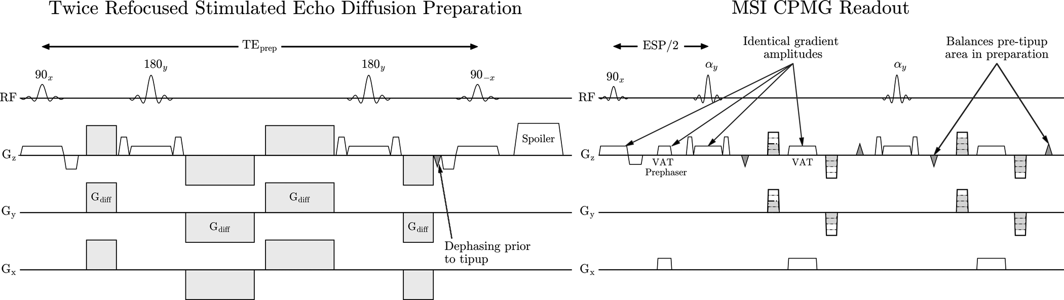
Stimulated echo diffusion preparation that corrects non-CPMG artifacts. Dephasing prior to tipup ensures uniform signal is returned to the longitudinal axis, regardless of phase from bulk motion. View Angle Tilting (VAT) gradients are applied during readout to reduce in-plane distortion as in most selective MSI methods.
2.2 |. Effect of Static Background Gradients on Diffusion Weighting
The effect of static background gradients was known empirically in early NMR diffusion work [28], and can be considered as a spatially varying, “always on” gradient with unknown amplitude and polarity. For a monopolar pulsed gradient spin-echo sequence, the background gradient increases or decreases the amplitude of the applied diffusion gradient and changes the achieved b-value. An analysis of interactions between background gradients and diffusion weighting was introduced in [29] by Williams et al.
Diffusion-related attenuation is associated with the b-value [30], given by:
| (1) |
Where F(t) = Fdiff(t) + Fbg(t) and:
| (2) |
| (3) |
In Equations 2 and 3, gdiff(u) is the applied diffusion gradient and gbg(u) is the background gradient. Expanding the integrand in Equation 1 gives:
| (4) |
In Equation 4, Fdiff(t)2 is the desired b-value contribution, and Fbg(t)2 is cancelled after division by the b = 0 s/mm2 image, leaving the cross-term Fbg(t)Fdiff(t). For the twice-refocused M0-nulled diffusion encoding shown in Figure 1, Fbg(t)Fdiff(t) = 0, which implies the background gradient has no effect on ADC quantification. This is illustrated in Supporting Information Figure S1. Diffusion encoding schemes that are insensitive to background gradients are not unique and single-refocused options exist. The effect of background gradient cannot be removed from the diffusion weighted image, similar to T1 or T2 “shine-through”.
2.3 |. Diffusion Preparation with Root-Flipped SLR Refocusing Pulses
In MSI, the excitation bandwidth of each spectral bin (generally 1−1.5 kHz) and slice-select gradient amplitude must be precisely managed. Due to off-resonance, the same slice-select gradient amplitude must be applied for both preparation and readout to ensure that the same spatial locations are prepared, excited, and imaged, regardless of resonance frequency. This is akin to matching the excitation k-space velocity of both the preparation and CPMG echo train so that off-resonance induced spatial shifts appear identical. In conventional diffusion preparation, the slice thickness that is prepared is often widened to increase the region that experiences 180° refocusing, and can be trivially achieved by reducing the amplitude of the slice-select gradient. This is not possible for MSI, since the slice-select gradient amplitudes in the preparation and readout must be equal. MSI sequences must therefore consider only the RF BW of the preparation instead of the combination of RF BW and gradient amplitude.
One method of preparing an excitation bandwidth larger than the readout is to reduce the spectral width of each bin, but this increases the scan time required to maintain the same total spectral coverage, on the order of ±12 kHz at 3T for the most severe implants. It is desirable to maximize the bandwidth of the preparation, but a short, high time-bandwidth (TBW) 180° pulse can easily exceed the peak B1 limit. Variable rate selective excitation (VERSE) pulses can reduce SAR and peak B1 but the non-constant gradient (and excitation k-space velocity) results in smearing of the slice profile in the presence of off-resonance [31].
To create a short 180° pulse with high TBW, we relax the linear phase constraint on the slice profile of the refocusing pulse. This constraint can be relaxed because signal attenuation from diffusion-sensitizing gradients is dependent on the magnitude of the nutation created by the refocusing pulse, not its axis of rotation. We employ Shinnar-Le Roux (SLR) pulses [26] and root-flipping to obtain a non-linear phase refocusing with reduced peak B1. The SLR algorithm represents RF pulses as two complex polynomials AN(z) and BN(z) which can be approximated using digital filter algorithms. The Fourier transform of the BN(z) polynomial is referred to as the beta profile β. By applying root-flipping to the beta profile of the refocusing pulse, the peak B1 of the refocusing pulse can be reduced by 30–45% while maintaining the same flip angle amplitude profile [32].
2.4 |. Reducing B1 Sensitivity of the Stimulated Echo Diffusion Preparation with a Twice-Refocused Spin-Echo and an Identical Phase Pulse
In most literature employing non-linear phase refocusing pulses, the phase of the 90° excitation is “matched” with that of the refocusing pulse to create a linear phase coherent spin-echo [33, 34]. The rotation axes for linear phase and matched pulse pairs are illustrated in Figure 2A and B. Matched phase SLR pulses have been effectively applied to diffusion preparation using adiabatic spin-echoes at 7T [35, 36, 37].
FIGURE 2:
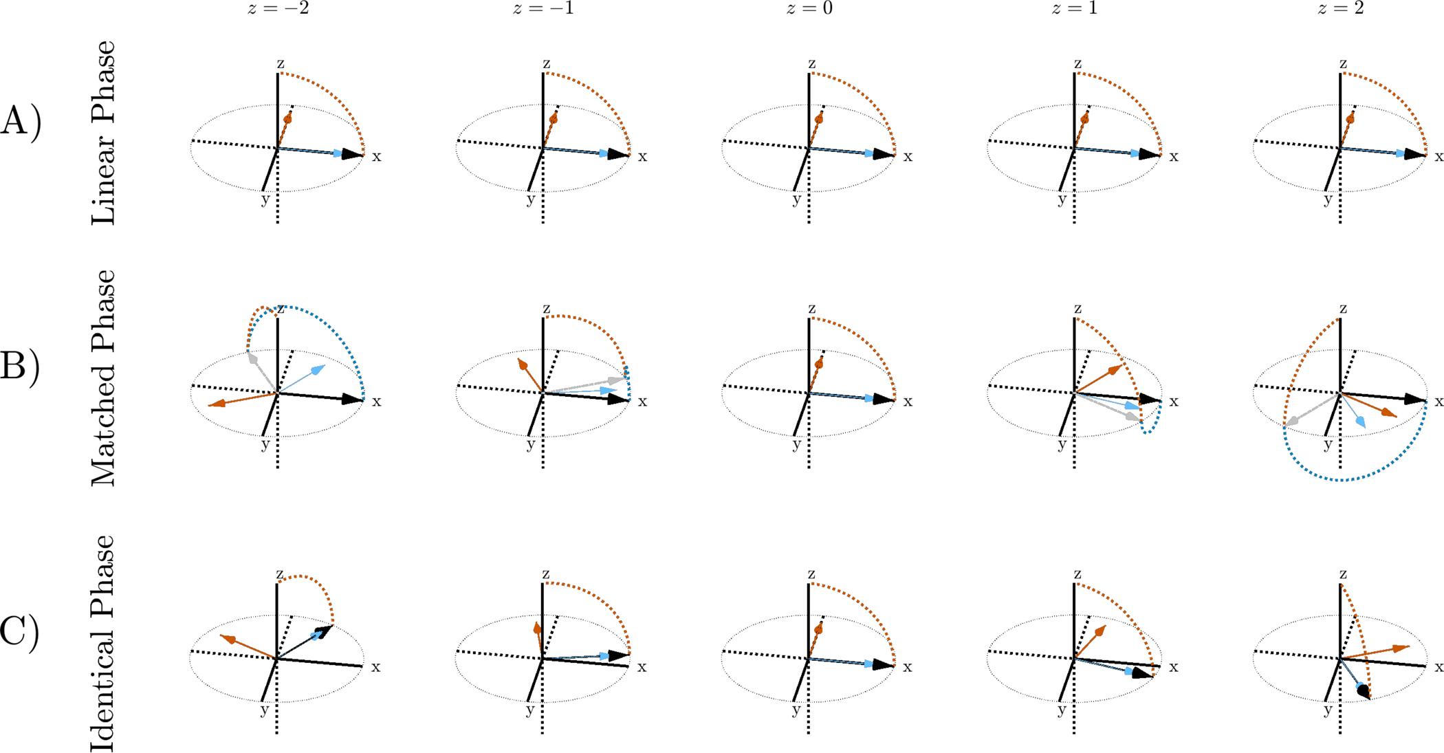
Magnetization path for different pulse pairs at separate locations in the slice profile after excitation and refocusing. During excitation, the magnetization rotates about the orange arrow and follows the path denoted by the orange dotted line. During refocusing, the magnetization vector rotates about the blue arrow. A) Linear phase pulses have a rotation axis that is constant in the slice direction. The refocusing axis of rotation is offset 90° from the excitation to satisfy the CPMG condition. B) Excitation and refocusing rotation axes are matched so that the magnetization is aligned along the x direction at the end of the pulse pair. The gray arrow represents the magnetization after excitation. The rotation axes vary across the slice. C) With an identical phase pulse pair, magnetization at the end of the 90–180 pair does not have linear phase but the CPMG condition is satisfied within the slice.
We now introduce the “identical phase” pulse pair, illustrated in Figure 2C. An identical phase excitation or tipup is a 90° pulse whose slice phase profile is the same as the slice phase profile of its non-linear phase refocusing pair. The beta profile of the identical phase pulse satisfies:
| (5) |
The transverse magnetization after an identical phase pulse pair can be computed using the alpha and beta profiles. For any general excitation and refocusing pulse pair:
| (6) |
The transverse magnetization after an identical phase pulse pair using Equations 5 and 6 is:
| (7) |
In Equation 7, the phase profile of the excitation-refocusing pulse pair is equal to that of the initial excitation assuming little phase contribution from α90 exc. This pulse combination was introduced by Pauly et al. in [27] for 3D imaging and creates a phase modulation along the slab dimension that was resolved during image encoding.
The stimulated echo diffusion preparation shown in Figure 1 is a stand-alone module consisting of excitation, refocusing, and tipup pulses where a linear phase coherent echo does not need to be formed within the preparation. To avoid subvoxel cancellation during readout, a uniform longitudinal magnetization profile is required at the end of the preparation. This is distinct from matched pulse pairs where a linear phase transverse magnetization is formed after two pulses. Unaccounted non-linear phase from the root-flipped refocusing pulse causes cancellation within the voxel for slice-selective 2D imaging and MSI where the kz phase encoding resolution is much coarser than the excited slice thickness (kzmax = 0 cm−1 for 2D).
The longitudinal magnetization mz after applying a tipup to any general mxy is:
| (8) |
Substituting mxy from Equation 6 into Equation 8 and assuming a single-refocused preparation gives:
| (9) |
The uniform longitudinal magnetization constraint requires mz = 1, which can be satisfied in many different ways using either single-refocused or twice-refocused preparations.
For single-refocused preparations, a matched excitation-refocusing pulse pair and linear phase tipup can be used, but this configuration is asymmetric which can be sensitive to phase reference errors. A symmetric, single-refocused preparation that creates a uniform longitudinal magnetization is a 90identical phase · 180non-linear phase · −90identical phase scheme. This single-refocused preparation with identical phase 90° pulses is sensitive to B1 inhomogeneity because B1 inhomogeneity changes the achieved phase profile of non-linear pulses, and the phase profile of the scaled 90° will not compensate the phase of the scaled refocusing pulse. A twice-refocused preparation circumvents this issue since repeating a non-linear phase refocusing pulse cancels its phase contribution. As described in Section 2.2, twice-refocused M0-nulled diffusion encoding is also insensitive to background gradients.
A twice-refocused preparation can achieve uniform mz using a linear phase excitation and tipup with two non-linear phase refocusing pulses. However, this preparation violates the CPMG condition at the slice level. The CPMG condition requires that the phase of the refocusing pulse be shifted 90° to the phase of the excitation when multiple refocusing pulses are applied [10]. If the CPMG condition is not met, the amplitude of the spin-echo is considerably reduced when the refocusing flip angle is not precisely 180°.
Instead of a linear phase excitation and tipup, identical phase pulses can be used to satisfy the CPMG condition while achieving a uniform mz at the end of the preparation. The CPMG condition is satisfied because the rotation axis of the refocusing pulse is offset 90° from the excitation rotation axis everywhere within the slice. From Equation 7, subsequent applications of the same refocusing pulse after the initial 90–180 continue to satisfy the CPMG condition. Non-linear phase from the excitation is eliminated by negating the tipup amplitude and repeating the refocusing pulse cancels its phase contribution. We refer to a preparation with identical phase 90° pulses and non-linear phase refocusing pulses as a “non-linear phase CPMG preparation”.
3 |. Methods
3.1 |. Sequence and Reconstruction
The stimulated echo diffusion preparation with SEMAC encoding [5] and a linear phase preparation is shown in Figure 1. View Angle Tilting (VAT) gradients suppress in-plane off-resonance artifacts and kz phase encoding reduces through-slice distortion to avoid pileup and dropout. The preparation is nearly identical to that used in [15] and [16], except we employed the twice-refocused non-linear phase CPMG diffusion preparation to maximize the RF bandwidth of the preparation. All slice-select gradients have equal gradient amplitude and 2 cycles of spoiling across the nominal slice width was applied prior to the tipup.
A challenge with 3D diffusion imaging is the correction of shot-to-shot phase from motion sensitizing diffusion gradients. Multiplexed Sensitivity Encoding (MUSE) [38] is commonly used in 2D, which applies parallel imaging to reconstruct a low-resolution phase navigator for each shot. Applying MUSE to 3D acquisitions is difficult since the undersampling factor in ky-kz for each shot is too high to reconstruct the navigator. Directly sampling a low-resolution phase navigator every shot would harm scan efficiency, since a large fraction of each echo train would be dedicated to sampling the low-resolution ky-kz region. We correct for shot-to-shot phase by observing that the majority of the signal in each bin exists in a contiguous slab. Therefore, a 2D projection of the phase navigator in the xy-plane is a fair approximation of the spatial phase variation. Although out-of-plane spins are ignored with this phase correction method, coherent ghosting from these regions is reduced by randomly distributing ky-kz phase encodes between shots.
The low-resolution 2D phase navigator was acquired during the pseudo-steady-state stabilization of the VFA train as previously employed for 3D TSE diffusion [39]. The phase navigator was 4 lines with Ry = 2. Images were reconstructed using coil sensitivities estimated with ESPIRIT [40] from b=0 s/mm2 images.
3.2 |. RF Pulse Design and Simulations
A minimum-phase SLR pulse with TBW 5 was used to initialize the root-flipping algorithm, and SLR design relations [26] were used to achieve an effective slice profile passband ripple δ1e = 0.005 and stopband ripple δ2e = 0.001. The associated minimum-phase, minimum power AN(z) polynomial was used. Monte Carlo root-flipping with 100 iterations was applied with each root having a 0.5 probability of being flipped.
The slice profile of the complete preparation was simulated for B1 inhomogeneities ranging from 0.7 to 1.0 and included crusher gradients (10 cycles across the nominal slice thickness). Three different preparations were simulated: single-refocused with non-linear phase refocusing and identical phase excitation and tipup, twice-refocused with non-linear phase refocusing and linear phase excitation and tipup, and twice-refocused with non-linear phase refocusing and identical phase excitation and tipup. Simulations were performed for a phase insensitive preparation with 2 cycles of spoiling prior to tipup. The total signal was computed by summing the magnetization after the tipup assuming that the stimulated echo is completely rephased during readout.
3.3 |. Phantom Validation
The non-linear phase CPMG diffusion preparation was validated in three phantom acquisitions. Phantom acquisitions were performed at 3T on a GE Healthcare (Milwaukee, WI) Signa Premier with constant refocusing flip angle 120° and diffusion gradients designed with 50 mT/m per axis amplitude and 40 T/m/s slew rate.
First the B1 sensitivity of the preparation was evaluated by acquiring the center slice of a uniform agar ball using a 2D CPMG echo train and the following twice-refocused preparations: entirely linear phase pulses, root-flipped refocusing with linear phase excitation and tipup, and root-flipped refocusing with identical phase excitation and tipup. Scan parameters: FOV = 20 cm, slice thickness = 5 mm, matrix size = 96×96, b = 0 s/mm2, TEprep = 55 ms (as indicated in Figure 1), ETL = 16, 48-channel head coil. A B1 map was acquired using Bloch-Siegert shift B1 mapping [41].
Next the effect of increased RF bandwidth was tested by using a 3D MSI readout to scan a phantom consisting of a total shoulder replacement (Biomet U.K. Ltd.) composed of a cobalt-chromium alloy head and titanium alloy stem submerged in agar and embedded in a 3D grid. This phantom exhibits severe off-resonance and B1 shading. The spectral widths of the CPMG echo train/ preparation/ bin separation were: 600/ 800/ 500 Hz for linear refocusing, and 1200 / 1500 / 1000 Hz for root-flipped refocusing, each having the same maximum B1 amplitude of 0.18 G. The evaluated preparations were the same as the agar ball experiment. Scan parameters: FOV = 26 cm, slice thickness = 5 mm, 16 bins, matrix size = 128×128×16, b = 0 s/mm2, 32-channel anterior Air Coil (GE Healthcare), ETL = 12 for low bandwidth preparation and 24 for high bandwidth preparation, TEprep = 55 ms, readout bandwidth = ±125 kHz. Since RF BW affects echo spacing, the ETL was changed to maintain similar T2 blur.
Finally, the ability to reliably quantify diffusion weighting in the presence of metal was tested at ambient room temperature in a diffusion phantom consisting of vials with varying concentrations of H2O dissolved in acetone [42]. Acetone vials were arranged annularly around the femoral head of a total hip arthroplasty. This phantom allows for easy removal of the implant head to compare ADCs with and without metal-induced off-resonance. Scan parameters were: in-plane resolution 2 × 2 mm, b-value = 0, 500 s/mm2, 24 bins, bin bandwidth = 1.5 kHz, ETL = 24. Mean ADC values in each vial obtained with and without metal were compared using linear regression analysis.
To demonstrate the sensitivity of ADC to static background gradients from metal, we acquired DW-MSI using twice-refocused M0 and M1-nulled waveforms with two diffusion encoding directions. The second direction negated the amplitude of all diffusion gradients, which would ideally yield identical diffusion weighting and ADC maps in the absence of background gradients since the acetone-H2O phantom exhibits isotropic Gaussian diffusion [42].
3.4 |. in vivo Experiments
The twice-refocused non-linear phase CPMG diffusion preparation with identical phase excitation and tipup was used for all in vivo DW-MSI acquisitions.
A 46-year-old female volunteer with two titanium screws from anterior cruciate ligament (ACL) reconstruction surgery was scanned with approval of the local Institutional Review Board and informed consent at 3T (GE Signa Premier). DW-MSI (b = 400 s/mm2) was compared to self-navigated 4-shot DW-EPI with spectral-spatial fat suppression and reconstructed with MUSE [38]. DW-MSI scan parameters are shown in Table 1. DW-EPI scan parameters were: matrix 192 × 192, voxel size 0.8 × 0.8 × 4 mm, TR = 2500 ms, TE = 62 ms, 2 NEX b=0 s/mm2, 6 NEX b=400 s/mm2. Vendor PD and Short-T1 Inversion Recovery (STIR) MAVRIC-SL were acquired for comparison.
TABLE 1:
Sequence parameters for in vivo DW-MSI acquisitions
| DW-MSI Parameters | ACL Reconstruction Surgery (3T) (46-year-old female) |
Unilateral Hip Replacement (1.5T) (25-year-old female) |
Unilateral Hip Replacement (1.5T) (9-year-old female) |
Bilateral Intramedullary Rods (1.5T) (11-year-old male) |
|---|---|---|---|---|
| FOV [cm] | 16 × 16 | 45 × 36 | 30 × 18 | 35 × 35 |
| Matrix Size | 192 × 192 × 16 | 256 × 100 × 32 | 256 × 76 × 16 | 128 × 128 × 24 |
| Voxel Size [mm] | 0.8 × 0.8 × 4 | 1.7 × 3.6 × 5 | 1.2 × 2.4 × 5 | 2.7 × 2.7 × 5 |
| b-value [s/mm2] | 0, 400 | 0, 500 | 0, 500 | 0, 400 |
| NEX [b0/bx] | 1 / 2 | 0.7 / 0.7 | 0.7 / 0.7 | 0.7 / 0.7 |
| Readout BW [kHz] | ±100 | ±100 | ±125 | ±100 |
| TR [ms] | 2500 | 4500 | 6500 | 4500 |
| TE prep [ms] | 41 | 55 | 55 | 50 |
| ETL | 68 | 68 | 68 | 68 |
| Bins | 8 | 8 | 8 | 8 |
| Bin Bandwidth [kHz] | 1.2 | 1.2 | 1.2 | 1.2 |
| Scan Time | 9:56 | 8:40 | 5:08 | 8:40 |
The DW-MSI sequence was appended to clinical exams of three patients (two with unilateral hip replacements, one with bilateral intramedullary rods) following informed consent and IRB approval. These acquisitions were performed at 1.5T (GE Healthcare Optima 450W) with 30 mT/m per axis diffusion gradient amplitude and 20 T/m/s slew rate. The exam included T1-weighted and STIR MAVRIC-SL.
4 |. Results
4.1 |. RF Pulse Design and Simulations
The refocusing pulse obtained using the root-flipping method and its identical phase pair are shown in Figure 3. Root- flipping reduced the peak B1 of the refocusing pulse from 0.34 G to 0.19 G for a 3.24 ms pulse, 1.6 kHz bandwidth at 90% of maximum profile.
FIGURE 3:
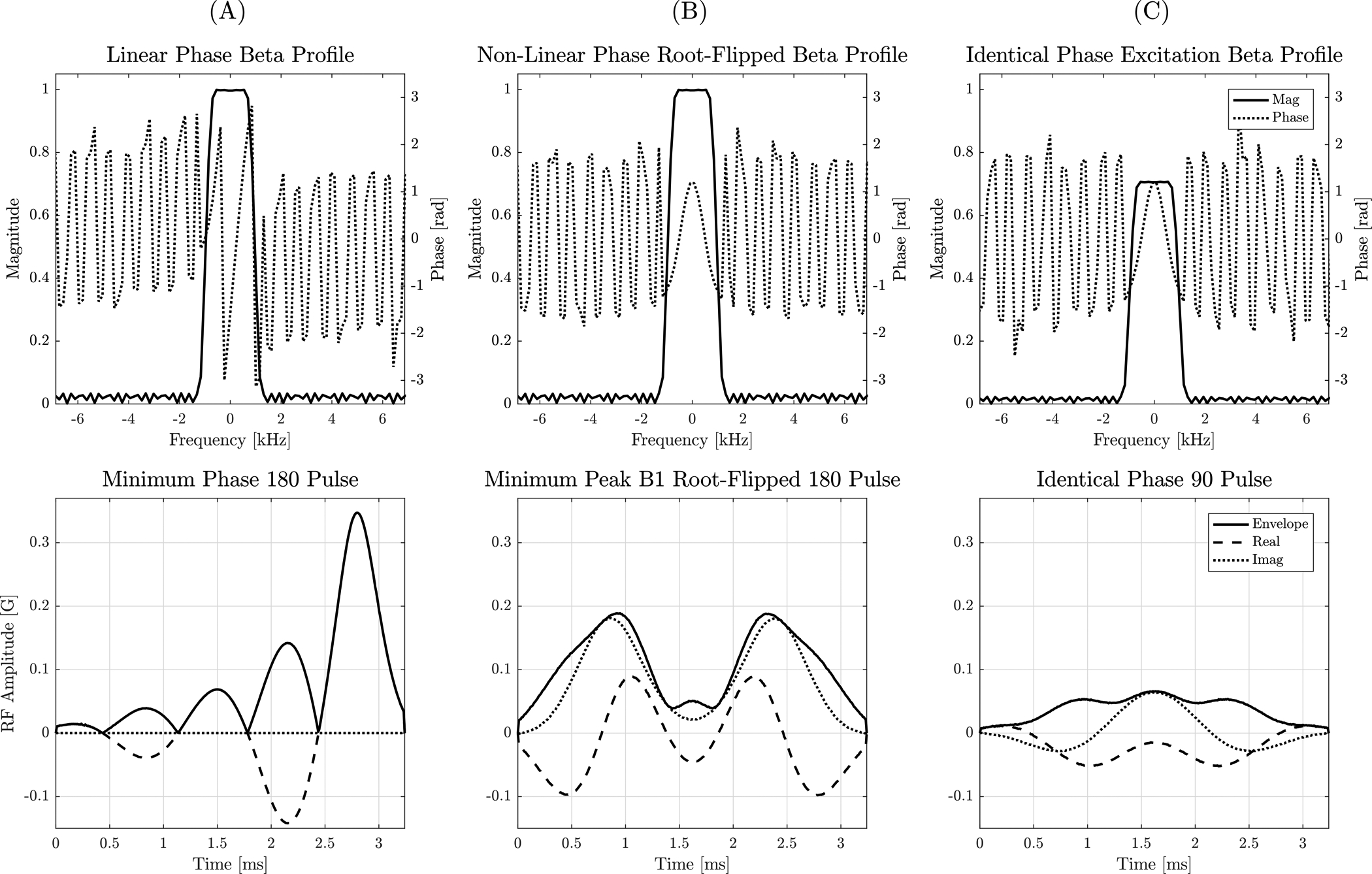
Top: Beta magnitude and phase profile of a minimum-phase, TBW 5 SLR pulse (A) compared to the beta profile of the minimum peak B1 RF obtained using root-flipping (B). The phase of the excitation beta profile (C) is identical to that of the refocusing pulse. Bottom: RF pulse obtained using the SLR transform and a minimum-phase alpha polynomial. The root-flipping algorithm reduces the peak B1 from 0.34 G to 0.19 G. The root-flipped SLR approach enables the use of a short and high TBW refocusing pulse that remains within the maximum B1 limit.
Simulated slice profiles of different preparation schemes and B1 scales are shown in Figure 4. The ideal slice profile of cos2 2π(2z) from the stimulated echo pathway is plotted for reference. For B1 = 1.0, rapid oscillations are visible in the transition band of the preparation employing linear phase excitation and root-flipped 180s. This is because the achieved flip angle is not 180° in the transition band and the CPMG condition is not met with linear phase excitation. Fewer oscillations are observed in the transition band with identical phase pulses.
FIGURE 4:
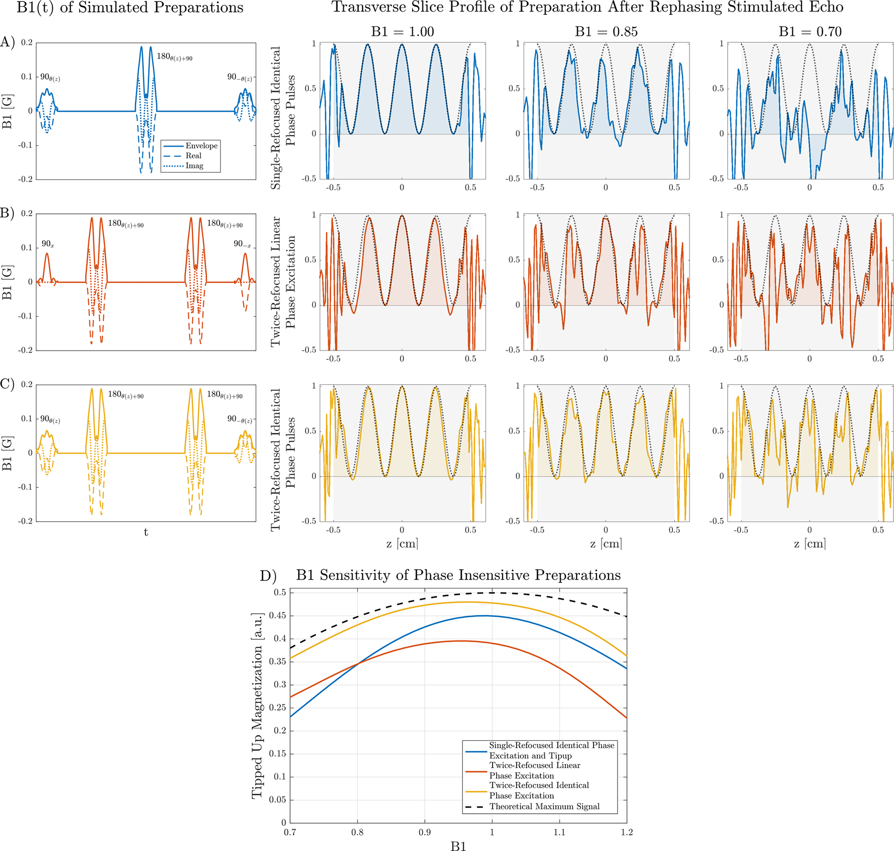
A-C) Simulated slice profiles of the transverse mx demonstrate the improvement of a twice-refocused, non-linear phase CPMG preparation (C) over single-refocused (A) and twice-refocused with linear phase excitation and tipup (B). RF waveforms are shown on the left, where subscripts x, y, denote linear phase slice profiles, and θ(z) a non-linear phase profile. The dotted line shows the ideal cos2 2π(2z) modulation resulting from rephasing the stimulated echo after 2 cycles of spoiling prior to the tipup. Negative mx values add destructively. D) The total signal, determined by the area in the shaded regions of the simulated slice profiles, shows the reduced B1 sensitivity of the twice-refocused scheme with identical phase 90s. The maximum value is 0.5 due to 2x signal loss from the stimulated echo pathway. The theoretical maximum signal assumes an ideal twice-refocused CPMG preparation.
For severe B1 inhomogeneity of 0.7, the profile using identical phase pulses is most similar to the ideal profile. The slice profile of the single-refocused preparation experiences the most severe degradation as B1 decreases because the phase profiles of the scaled non-linear excitation and refocusing are no longer identical. The effect of amplitude scaling is reduced when using a twice-refocused scheme since a refocusing pulse applied twice cancels its phase contribution.
The total signal of each preparation is plotted in Figure 4D. The identical phase excitation produces 20% more signal compared to a linear phase excitation at B1 = 1.0, and improves to 30% more signal at B1 = 0.7. This is consistent with non-CPMG effects becoming more prominent as the flip angle deviates further from 180°. The non-linear phase CPMG preparation achieves slightly less signal than the theoretical maximum at B1 = 1.0 mainly due to reduced performance in the transition band. The twice-refocused schemes are less sensitive to B1 compared to the single-refocused preparation but requires a 20–30% longer TE to achieve the same b-value.
4.2 |. Phantom Experiments and the Effect of Static Background Gradients
A comparison of b = 0 s/mm2 images acquired in a uniform agar ball acquired with different RF pulses is shown in Figure 5. A preparation with only linear phase pulses serves as a reference. Root-flipped 180s with a linear phase excitation has shading in the center of the phantom due to B1 inhomogeneity, shown in the B1 map. Employing root-flipped 180s with an identical phase excitation that satisfies the CPMG condition has similar shading to a solely linear phase preparation. The 1D profile of images acquired with root-flipped 180s normalized to the linear phase preparation is also shown. The identical phase excitation has a signal ratio near unity whereas the signal of the linear phase excitation is reduced by 20% at the center.
FIGURE 5:
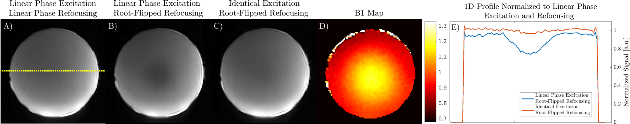
Effect of excitation beta profile on B1 sensitivity of preparations using root-flipped refocusing pulses in a uniform agar ball phantom. A) Center slice of the linear phase refocusing and excitation preparation with dotted yellow line showing location of extracted 1D signal profile. B) A linear phase excitation with root-flipped 180 has evident B1 shading, corresponding to the B1 map in D. C) An identical phase excitation with root-flipped 180 has similar shading to the linear phase preparation. The signal profiles of B and C normalized to the linear phase preparation in A are shown in E.
A fixed xy-slice in the shoulder phantom from excitations at different spectral offsets using preparations with different RF pulses is shown in Figure 6. Root-flipped 180s permit the bin bandwidth to be doubled and results in excitation of spins closer to the implant, visible in the bin with 0 kHz offset. Signal differences near the shaft using root-flipped refocusing pulses are likely due to T2 contrast differences created by B1 variations, which affects the stimulated echo pathway of the twice-refocused preparation by underflipping or overflipping magnetization into the longitudinal axis. High RF bandwidth improves MSI scan efficiency because the number of excitations required to cover the desired spectral range is decreased. The identical phase excitation reduces B1 shading above the implant and at the edges of the phantom. Signal improvement at the head of the implant is marginal due to the spectral coverage of the low bandwidth preparation being nearly sufficient to cover the range of off-resonance. The high bandwidth preparation could alternatively be used to achieve an image with equal spectral extent to the low bandwidth preparation in half the scan time.
FIGURE 6:
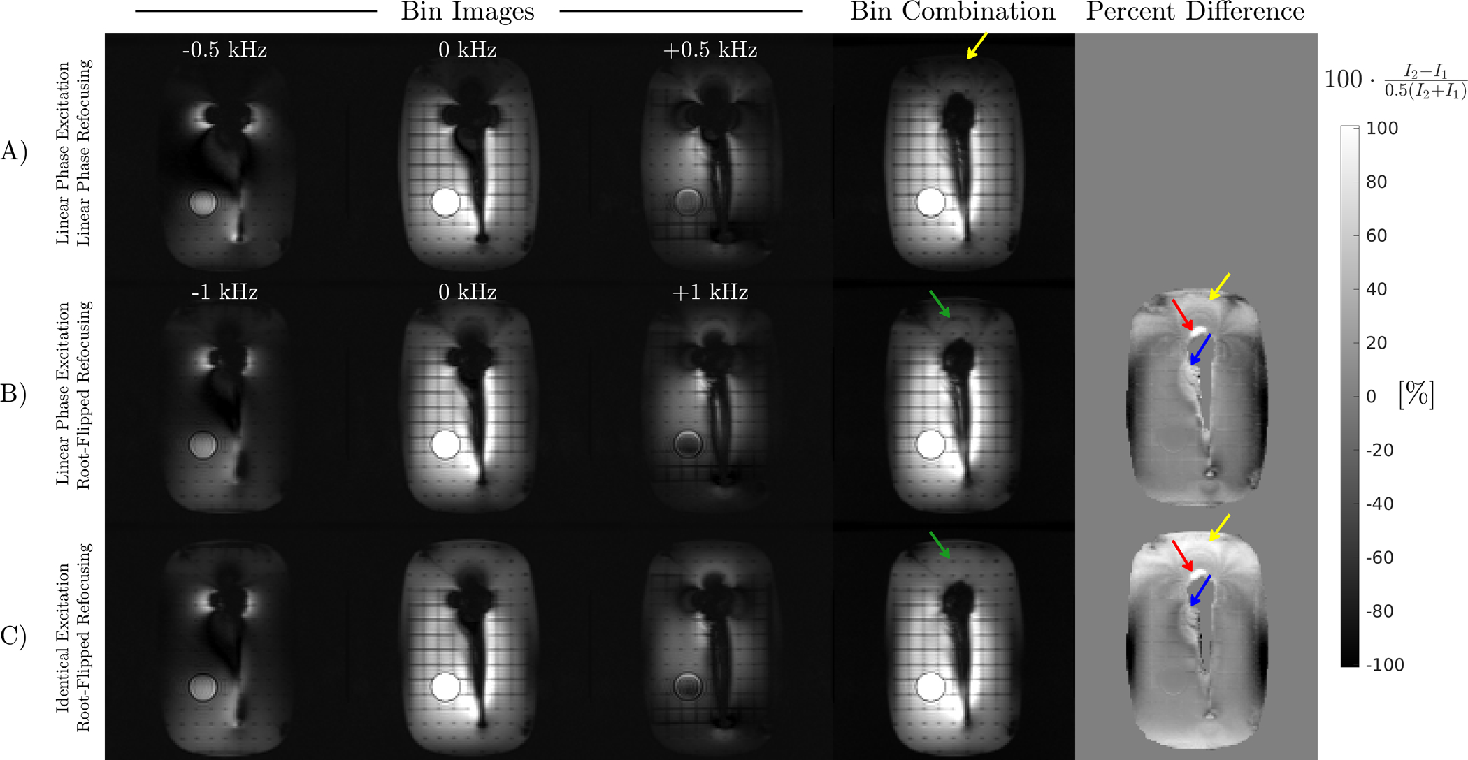
Three of the 16 acquired bin images at a fixed slice location from different preparation schemes and the sum-of-squares bin combination. The difference is calculated using the low bandwidth bin combined image as reference. Top row: Preparation with only linear phase pulses reduces the bin bandwidth, resulting in unexcited spins close to the head of the implant and above the phantom (yellow arrow). Middle row: A root-flipped refocusing pulse enables greater bin bandwidth, exciting spins that are not excited with the low bandwidth preparation (yellow, red arrows). Signal differences adjacent to the shaft (blue arrow) are likely due to B1 affecting the stimulated echo pathway. B1 inhomogeneity also causes band-like signal loss above the head. Bottom row: An excitation with identical phase to the root-flipped refocusing pulse reduces band-like signal loss above the implant (green arrow).
DW-MSI images and ADC maps obtained with and without metal in the acetone diffusion phantom are shown in Figure 7. Regression analysis between mean ADCs in each vial with and without metal gave the following linear fit: ADCwith metal = 0.945 · ADCno metal + 0.05 × 10⁻³ mm2/s, R2 = 0.97, p < 0.001. The twice-refocused, M0-nulled diffusion encoding in Figure 1 is insensitive to static background gradients [28, 29, 43, 44]. While the background gradient affects diffusion weighting in the b = 0 s/mm2 image, the net effect after computing SDWI /Sb0 is zero. This can be observed in Figure 7 by the excellent ADC correspondence between H2O a few millimeters away from the implant and reference H2O vials.
FIGURE 7:
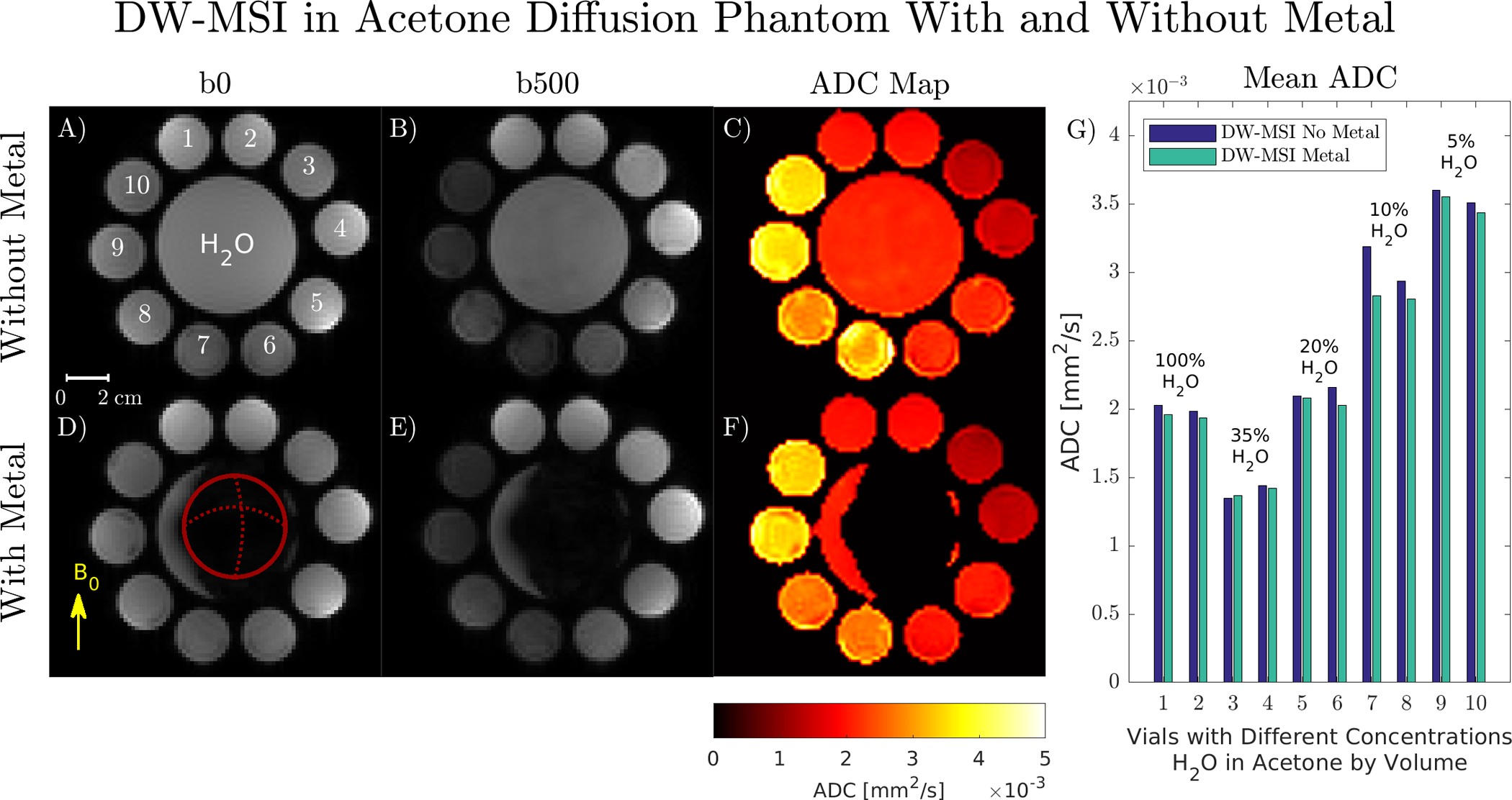
A-F) DW-MSI b = 0, 500 s/mm2, and calculated ADC maps obtained with and without metal using a twice-refocused M0-nulled sequence. ADC maps are unaffected by the static background gradient caused by metal-induced off-resonance and exhibit no spatial distortion due to B0 inhomogeneity. The femoral head lies in-plane, denoted by the circle in (D). G) Mean ADC values in each vial with the corresponding H2O/acetone concentrations by volume.
With a twice-refocused M1-nulled diffusion encoding, background gradients affect diffusion weighting since the cross-term Fbg(t)Fdiff(t) is non-zero, as evaluated in Supporting Information Figure S1. ADC values are biased in regions with spatially rapid field variation, shown in Supporting Information Figure S2. ADC maps obtained with M1-nulled waveforms, shown in Supporting Information Figure S3, demonstrate anisotropy in regions with rapid field variation as in Supporting Information Figure S4.
4.3 |. in vivo Experiments
The slice containing the screw in the subject with ACL reconstruction surgery is shown in Figure 8. The metal screw (green arrow) causes severe pileup artifacts in DW-EPI. The proposed DW-MSI sequence permits calculation of ADC in bone marrow adjacent to the screw, which had a mean less than0.1 × 10−3 mm2/s because no fat suppression was used [45]. ADCs in cartilage (purple arrow), were 1.8 ± 0.2 × 10⁻³ mm2/s and 1.7 ± 0.3 × 10⁻³ mm2/s for DW-EPI and DW-MSI respectively (mean, standard deviation). Joint fluid (blue arrow) ADCs were 2.7 ± 0.2 × 10⁻³mm2/s for DW-EPI, and 2.4 ± 0.4 × 10⁻³mm2/s for DW-MSI.
FIGURE 8:
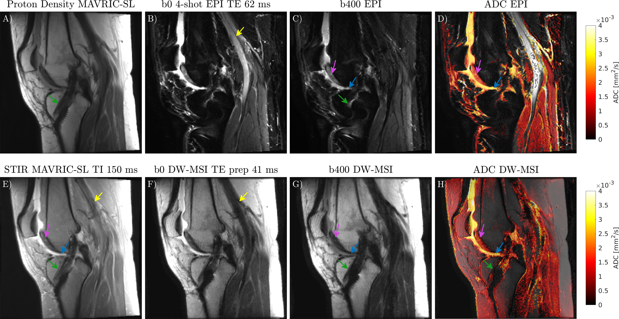
Comparison of ADC maps overlaid on b = 0 s/mm2 images acquired with DW-MSI and DW-EPI in subject with ACL reconstruction surgery, with reference PD and STIR MAVIRC-SL. The metal screw (green arrow) causes severe distortion in DW-EPI. DW-MSI corrects these distortions and permits ADC calculation in tissue near the screw. Cartilage (purple arrow), and joint fluid (blue arrow) are visible on both DW-EPI and DW-MSI. The popliteal artery (yellow arrow) is bright on b0 DW-EPI but not b0 DW-MSI due to first order moments in the CPMG refocusing train and a small minimum refocusing flip angle.
Flow along the frequency encode direction in the popliteal artery (yellow arrow) is visible in b=0 s/mm2 DW-EPI and STIR MAVRIC-SL but not in DW-MSI. The CPMG refocusing train has large first moment differences between the stimulated and spin-echo components [46] which accumulate due to small refocusing flip angles [47].
Images acquired in clinical exams are shown in Figure 9. T1-weighted and STIR MAVRIC-SL acquired in the same exam are provided for reference. Patient 1 is a 25-year-old female with proximal femoral osteosarcoma status post resection and placement of a hip arthroplasty which includes multiple additional fixation screws. Marked edema of the visualized extremity is due to treatment related lymphedema. Subcutaneous fluid visible in STIR MAVRIC-SL is also visible in ADC maps obtained with DW-MSI. ADCs in the subcutaneous fluid pockets (dashed white arrows) are between 2.5 – 3.0 × 10⁻³ mm2/s but are affected by partial voluming with fat. Soft tissue edema in the combined ROI indicated by dotted white arrows had an overestimated ADC of 3.5 ± 0.3 × 10⁻³mm2/s. Patient 2 is a 9-year-old female with a mid to proximal femoral endoprosthesis and hip arthroplasty for treatment of Ewing’s sarcoma. SNR is lower due to smaller voxel size and shorter scan time of 5 minutes. ADCs in the blue circle muscle ROI are noisy, but in a reasonable range of 1.2 ± 0.5 × 10⁻³mm2/s [48]. Reduced spectral coverage compared to MAVRIC-SL results causes signal loss near the head. Unresolved shot-to-shot phase due to the low resolution of the phase navigator results in signal loss and ADC overestimation in subcutaneous fat. Patient 3 is an 11-year-old male with bilateral intramedullary rods for bilateral proximal femoral pathologic fracture fixation. Fluid above the right femur had an ADC of 2.7 ± 0.2 × 10⁻³mm2/s.
FIGURE 9:
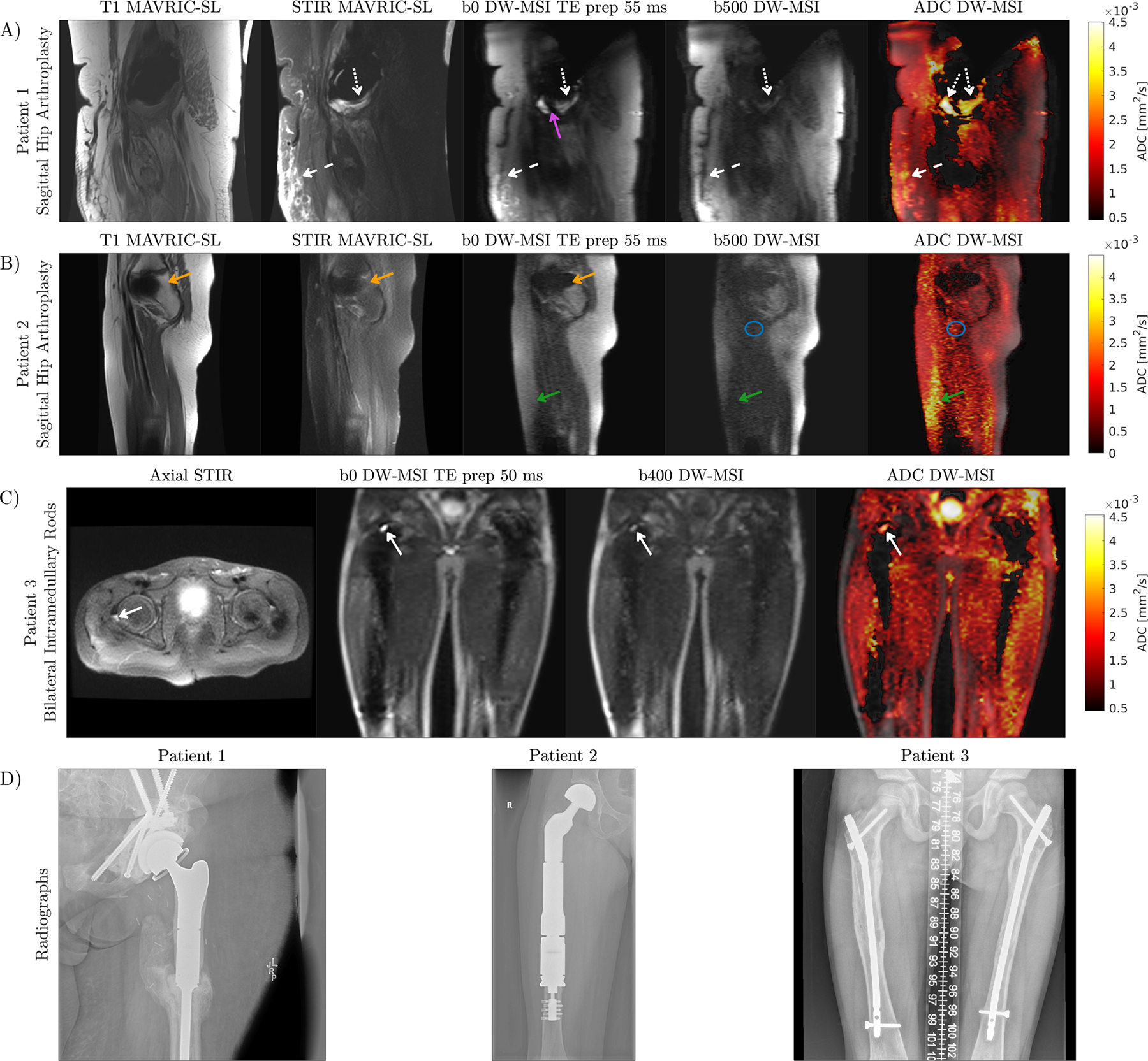
A) Patient with unilateral hip replacement. Fluid that is bright on STIR MAVRIC-SL (dashed white arrows), appears on the ADC map as an elevated ADC. Soft tissue edema is indicated by the dotted white arrows. DW-MSI has reduced spectral coverage compared to MAVRIC-SL due to limited scan time, resulting in signal appearing on MAVRIC-SL but not in DW-MSI (purple arrow). B) The green arrow indicates an area where the phase navigator resolution was too low, resulting in loss of signal and ADC overestimation. A signal void due to reduced spectral coverage relative to MAVRIC-SL is present on DW-MSI (orange arrow). C) Patient with bilateral hip replacement has a small amount of fluid above the right femur (solid white arrow) which can be visualized with DW-MSI and appears on axial STIR. D) Coronal radiographs for implant visualization.
5 |. Discussion
We have presented a sequence that combines a stimulated echo diffusion preparation with multispectral CPMG spin-echo trains, permitting diffusion weighted imaging with volumetric coverage near metal in clinically feasible scan times. Our method has increased spectral coverage and SNR efficiency compared to 2D DW-MSI [22]. We elected to use a stimulated echo diffusion preparation for removing non-CPMG artifacts, but other alternatives exist.
The SPLICE method [13] splits CPMG and non-CPMG components into two echoes, resulting in a SNR loss and marginally increased echo spacing. The two echoes can be combined with magnitude summation, but complex summation with a navigator echo is necessary to reduce ghosting artifacts [12].
Le Roux proposed that a quadratic phase increment between refocusing pulses [14] can be used to measure the full signal in a single echo, but this requires additional phase encodes or solving a parallel imaging problem to reconstruct the full FOV [49]. Quadratic phase modulation also requires flip angles greater than 150° to produce a stable echo train, which can quickly exceed SAR limits. This approach is not well suited for MSI which requires 3D encoding, high RF bandwidth, and multiple slice/bin excitations per TR.
Signal near metal can be encoded using readouts other than CPMG echo trains, hence avoiding the need to account for non-CPMG magnetization.
UTE MAVRIC approaches can resolve metal-induced off-resonance artifacts [50, 51]. UTE readouts have been paired with diffusion weighted driven equilibrium preparations and phase-cycled tipups (90x · 180y · 90−x,−y) to obtain diffusion weighted images relatively free of distortion [52]. Phase-cycling reduces shading artifacts from random phase but requires two acquisitions with different tipup phases and is sensitive to intra-scan motion which may change the diffusion-prepared magnetization that is returned to the longitudinal axis. Stimulated echoes can reduce the shading artifact, but the increased echo time causes signal loss near the implant due to T2* [50].
SPatial temporal ENcoding (SPEN) methods can achieve diffusion contrast [53], and have demonstrated resistance to field inhomogeneities from titanium screws [54] by limiting the spatial extent of spins using a method similar to 2D MSI where the intersection of slice-select bands is manipulated with gradient reversal. SPEN is a possible encoding for DW imaging near metal, but slice-select gradient reversal is SNR inefficient because it reduces the number of spins that are measured each excitation.
An alternative diffusion preparation is the Stimulated Echo Acquisition Mode (STEAM) [55] where the maximum preparation flip angle is 90°. This circumvents the peak B1 constraint but results in an additional 2× signal loss.
Non-linear phase CPMG excitation and root-flipped refocusing was applied to reduce the sensitivity of the diffusion preparation slice profile to B1 inhomogeneity. We attributed B1 sensitivity of the root-flipped refocusing pulse to phase differences between excitation and refocusing that occur within the slice profile and prevent CPMG, which was remedied using identical phase pulses. In [35], a twice-refocused spin-echo using quadratic phase SLR pulses (which exhibit adiabatic properties) with linear phase excitation was compared to a matched 90–180 pulse pair for diffusion encoding at 7T. This twice-refocused spin-echo was more sensitive to B1, which may be due to non-CPMG effects. The identical phase excitation cannot be incorporated because no tipup pulse is used and diffusion weighted magnetization is immediately acquired using an EPI readout.
Several sources of error can bias ADC measurements in the presented sequence. First, no fat suppression method was employed. Due to off-resonance, STIR is the only option for robust fat suppression near metal implants, but this reduces the signal by ~40%. Future work will incorporate this inversion pulse, which can be added before the diffusion preparation with the appropriate inversion delay [17].
Static non-linear background gradients from metal-induced off-resonance constitute a possible source of ADC bias since the true diffusion encoding gradient is a superposition of the background gradient and the linear scanner gradient. These background gradients are proportional to field strength, and affect diffusion encoding in the monopolar pulsed gradient spin-echo that was used by Koch et al. We demonstrated that ADC values obtained with a twice-refocused M0-nulled scheme are not affected by the background gradient from metal, but a twice-refocused M1-nulled scheme can exhibit large ADC deviations and diffusion anisotropy adjacent to the metal. Geometric averaging of opposite diffusion encoding polarities also eliminates the cross-term [56]. Fieldmaps from in vivo acquisitions in Supporting Information Figure S5 and simulations of the background gradient created by a titanium total hip replacement shown in Supporting Information Figure S6, and knee fixation screws in [19] indicate that the magnitude of the background gradient’s linear component is negligible a few centimeters from the implant. For smaller metallic hardware or acquisitions where spectral coverage is not sufficient to excite spins adjacent to the implant, the effect of background gradient will not be observed [57] and is unlikely to affect diagnosis. Assessing the diagnostic value of accurate diffusion weighting and ADC quantification adjacent to the implant will be a topic of future studies, but clinical evaluation of multispectral sequences suggests that visualization of structures adjacent to implants is desirable and can affect diagnosis [4,58,59,60,61].
A low-resolution 2D projection of the phase was used to correct for motion-induced phase before shot combination. Using a 2D projection to correct for the phase of a thicker slab has been employed in multiple works for diffusion imaging in the brain [62,63,64]. Signal close to the metal lies outside the principal slice and its phase is not spatially encoded. When the projection produces a pileup artifact, the phase estimation may be incorrect if off-resonance spins are spatially distant from the slab. Ghosting artifacts from these regions are not apparent because these regions are small, and ghosting is distributed in the yz-plane. ADC overestimation can be observed in Figure 9 for Patients 1, 2, and in Supporting Information Figure S7, which compares ADC values calculated with and without phase navigator correction. Effects of shot-to-shot phase are exacerbated in DW-MSI due to its extremely high shot count. Center oversampling to improve the 2D phase navigator or motion-compensated diffusion gradients for implants with small background gradients may be advantageous.
6 |. Conclusion
Volumetric diffusion weighted imaging near metal can be achieved in clinically feasible scan times with a stimulated echo diffusion preparation and 3D CPMG spin-echo readouts. Root-flipped refocusing pulses increase spectral coverage and non-linear phase CPMG reduces sensitivity to B1. A twice-refocused, M0-nulled diffusion measurement is insensitive to static background gradients from metal that affect ADC quantification.
Supplementary Material
FIGURE S1: Evaluation of cross term in b-value expression when a background gradient is present. Left: The twice-refocused M0-nulled scheme shown in the top row has an odd Fbg(t) and even Fdiff(t), which will yield an inner product of zero in the cross-term. The b-value is not affected. Right: The twice-refocused M1-nulled scheme has an odd Fbg(t) and odd Fdiff(t). The cross-term will be non-zero, and the achieved b-value will depend on the polarity of the diffusion gradients.
FIGURE S2: Acetone diffusion phantom experiment with and without metal comparing twice-refocused M0 and M1-nulled encoding. Left: ADC maps computed from b500 images obtained with M1-nulled diffusion encoding deviate from the no-metal and M0-nulled ADC maps in regions with high background field variation. This is evident in H2O directly adjacent to the implant (white arrow) and in Vial 2. Right: Mean ADCs with M1-nulled diffusion encoding have large deviations from mean ADCs obtained without metal, and with metal using the M0-nulled diffusion encoding.
FIGURE S3: Left: Effect of diffusion gradient polarity on ADC maps. M1-nulled encoding with diffusion gradients played on all axes exhibits anisotropy near the metal in regions with rapid background field variation. Right: In-plane fieldmap estimated from spectral bin data. Field variations along the slice direction are not captured. The fieldmap is obtained by calculating the maximum intensity projection for each voxel along the bin dimension and determining the center frequency of the maximum signal bin.
FIGURE S4: Spectral b=0 s/mm2 images of acetone phantom for a fixed slice location shows severe off-resonance created by the implant head.
FIGURE S5: Low spectral resolution fieldmaps obtained from b=0 s/mm2 data show the background gradient in slices presented in the main text. The magnitude of the background gradient is dependent on the slice and the severity of the implant. Since the effect of background gradient on diffusion weighting is only present in regions adjacent to the implant, high spectral coverage is required to produce noticeable benefits from the background gradient insensitive diffusion encoding schemes.
FIGURE S6: Left: Field pattern from convolving a dipole pattern with the susceptibility map of a titanium hip replacement at 3T. Top Right: 1D profile of off-resonance along dashed black line. Bottom Right: Resulting local gradient computed with finite differences and expressed in [G/cm]. In regions less than 1 cm from the implant, the gradient from off-resonance is on the order of the diffusion gradients (3–5 G/cm) and can affect the achieved b-value in that voxel. This effect is negligible when the distance from the implant is greater than 2 cm.
FIGURE S7: Left: Comparison of ADC maps with and without phase navigator correction in a 42-year-old male with ACL reconstruction surgery. Due to extra signal loss from phase incoherence between shots, omitting the phase navigator causes ADC to be vastly overestimated. Right: Histograms of ADC values show that incorporating the phase navigator into the reconstruction reduces overestimation of ADC, although ADC in the tibia (blue circle) is slightly overestimated compared to previously reported ADC values.
Acknowledgements
GE Healthcare. Karolinska Neuro MR Physics group for pulse programming assistance.
Funding Information
NIH: R01 AR0063643, R01 EB017739, P41 EB015891, R01AR077706, NSERC: PGS-D, and GE Healthcare
References
- [1].Padhani AR, Liu G, Mu-Koh D, Chenevert TL, Thoeny HC, Takahara T, et al. Diffusion-weighted magnetic resonance imaging as a cancer biomarker: Consensus and recommendations. Neoplasia 2009;11(2):102–125. [DOI] [PMC free article] [PubMed] [Google Scholar]
- [2].Kremers HM, Larson DR, Crowson CS, Kremers WK, Washington RE, Steiner CA, et al. Prevalence of total hip and knee replacement in the United States. Journal of Bone and Joint Surgery - American Volume 2014;97(17):1386–1397. [DOI] [PMC free article] [PubMed] [Google Scholar]
- [3].Martin BI, Mirza SK, Spina N, Spiker WR, Lawrence B, Brodke DS. Trends in Lumbar Fusion Procedure Rates and Associated Hospital Costs for Degenerative Spinal Diseases in the United States, 2004 to 2015. Spine 2019;44(5):369–376. [DOI] [PubMed] [Google Scholar]
- [4].Koch KM, Brau AC, Chen W, Gold GE, Hargreaves BA, Koff M, et al. Imaging Near Metal with a MAVRIC-SEMAC Hybrid. Magnetic Resonance in Medicine 2011. jan;65(1):71–82. http://doi.wiley.com/10.1002/mrm.22523. [DOI] [PubMed] [Google Scholar]
- [5].Lu W, Pauly KB, Gold GE, Pauly JM, Hargreaves BA. SEMAC: Slice encoding for metal artifact correction in MRI. Magnetic Resonance in Medicine 2009. jul;62(1):66–76. http://doi.wiley.com/10.1002/mrm.21967. [DOI] [PMC free article] [PubMed] [Google Scholar]
- [6].Hayter CL, Koff MF, Shah P, Koch KM, Miller TT, Potter HG. MRI after arthroplasty: Comparison of MAVRIC and conventional fast spin-echo techniques. American Journal of Roentgenology 2011;197(3). [DOI] [PubMed] [Google Scholar]
- [7].Choi SJ, Koch KM, Hargreaves BA, Stevens KJ, Gold GE. Metal artifact reduction with MAVRIC SL at 3-T MRI in patients with hip arthroplasty. American Journal of Roentgenology 2015;204(1):140–147. [DOI] [PMC free article] [PubMed] [Google Scholar]
- [8].Liebl H, Heilmeier U, Lee S, Nardo L, Patsch J, Schuppert C, et al. In vitro assessment of knee MRI in the presence of metal implants comparing MAVRIC-SL and conventional fast spin echo sequences at 1.5 and 3 T field strength. Journal of Magnetic Resonance Imaging 2015;41(5):1291–1299. [DOI] [PMC free article] [PubMed] [Google Scholar]
- [9].Gutierrez LB, Do BH, Gold GE, Hargreaves BA, Koch KM, Worters PW, et al. MR imaging near metallic implants using MAVRIC SL: Initial clinical experience at 3T. Academic Radiology 2015;22(3):370–379. 10.1016/j.acra.2014.09.010. [DOI] [PMC free article] [PubMed] [Google Scholar]
- [10].Meiboom S, Gill D. Modified spin-echo method for measuring nuclear relaxation times. Review of Scientific Instruments 1958;29(8):688–691. [Google Scholar]
- [11].Alsop DC. Phase insensitive preparation of single-shot RARE: Application to diffusion imaging in humans. Magnetic Resonance in Medicine 1997;38(4):527–533. [DOI] [PubMed] [Google Scholar]
- [12].Williams CFM, Redpath TW, Norris DG. A novel fast split-echo multi-shot diffusion-weighted MRI method using navigator echoes. Magnetic Resonance in Medicine 1999;41(4):734–742. [DOI] [PubMed] [Google Scholar]
- [13].Schick F SPLICE: Sub-second diffusion-sensitive MR imaging using a modified fast spin-echo acquisition mode. Magnetic Resonance in Medicine 1997;38(4):638–644. [DOI] [PubMed] [Google Scholar]
- [14].Le Roux P Non-CPMG Fast Spin Echo with full signal. Journal of Magnetic Resonance 2002;155(2):278–292. [DOI] [PubMed] [Google Scholar]
- [15].Zhang Q, Coolen BF, Versluis MJ, Strijkers GJ, Nederveen AJ. Diffusion-prepared stimulated-echo turbo spin echo (DPsti- TSE): An eddy current-insensitive sequence for three-dimensional high-resolution and undistorted diffusion-weighted imaging. NMR in Biomedicine 2017;30(7):e3719. [DOI] [PubMed] [Google Scholar]
- [16].Van AT, Cervantes B, Kooijman H, Karampinos DC. Analysis of phase error effects in multishot diffusion-prepared turbo spin echo imaging. Quantitative Imaging in Medicine and Surgery 2017;7(2):238–250. [DOI] [PMC free article] [PubMed] [Google Scholar]
- [17].Gibbons EK, Vasanawala SS, Pauly JM, Kerr AB. Body diffusion-weighted imaging using magnetization prepared single- shot fast spin echo and extended parallel imaging signal averaging. Magnetic Resonance in Medicine 2018;79(6):3032–3044. [DOI] [PMC free article] [PubMed] [Google Scholar]
- [18].Busse RF, Hariharan H, Vu A, Brittain JH. Fast spin echo sequences with very long echo trains: Design of variable refocusing flip angle schedules and generation of clinical T2 contrast. Magnetic Resonance in Medicine 2006;55(5):1030–1037. [DOI] [PubMed] [Google Scholar]
- [19].Koch KM, King KF, Carl M, Hargreaves BA. Imaging near metal: The impact of extreme static local field gradients on frequency encoding processes. Magnetic Resonance in Medicine 2014;71(6):2024–2034. [DOI] [PubMed] [Google Scholar]
- [20].Malyarenko DI, Ross BD, Chenevert TL. Analysis and correction of gradient nonlinearity bias in apparent diffusion coefficient measurements. Magnetic Resonance in Medicine 2014;71(3):1312–1323. [DOI] [PMC free article] [PubMed] [Google Scholar]
- [21].Callaghan PT. Magnetic field gradients and spin translation. In: Translational Dynamics and Magnetic Resonance, first edit ed. Oxford University Press; 2011.p. 177–251. [Google Scholar]
- [22].Koch KM, Bhave S, Gaddipati A, Hargreaves BA, Gui D, Peters R, et al. Multispectral diffusion-weighted imaging near metal implants. Magnetic Resonance in Medicine 2018;79(2):987–993. [DOI] [PubMed] [Google Scholar]
- [23].Hargreaves BA, Taviani V, Litwiller DV, Yoon D. 2D multi-spectral imaging for fast MRI near metal. Magnetic Resonance in Medicine 2018;79(2):968–973. [DOI] [PMC free article] [PubMed] [Google Scholar]
- [24].Zhao X, Li Z, Gaddipati A. PROPELLER DUO: Applied to Diffusion-Weighted Imaging. In: Proceedings of the 17th Annual Meeting of ISMRM, Honolulu, Hawai’i; 2009. p. 3517. [Google Scholar]
- [25].Koch KM, Bhave S, Kaushik SS, Nencka AS, & Budde MD (2019). Multispectral diffusion-weighted MRI of the instrumented cervical spinal cord: a preliminary study of 5 cases. European Spine Journal, 29(5), 1071–1077. [DOI] [PMC free article] [PubMed] [Google Scholar]
- [26].Pauly J, Nishimura D, Macovski A, Roux PL. Parameter Relations for the Shinnar-Le Roux Selective Excitation Pulse Design Algorithm. IEEE Transactions on Medical Imaging 1991;10(1):53–65. [DOI] [PubMed] [Google Scholar]
- [27].Pauly JM, Wong EC. Non-Linear Phase RF Pulses for Reduced Dynamic Range in 3D Rare Imaging. In: Proceedings of the 9th Annual Meeting of ISMRM Glasgow, Scotland, UK; 2001. p. 688. [Google Scholar]
- [28].Packer KJ, Rees C, Tomlinson DJ. A modification of the pulsed magnetic field-gradient spin echo method of studying diffusion. Molecular Physics 1970;18(3):421–423. [Google Scholar]
- [29].David Williams W, Seymour EFW, Cotts RM. A pulsed-gradient multiple-spin-echo NMR technique for measuring diffusion in the presence of background magnetic field gradients. Journal of Magnetic Resonance 1978;31(2):271–282. [Google Scholar]
- [30].Bernstein MA, King KF, Zhou XJ. Chapter 9 - Motion-Sensitizing Gradients. In: Handbook of MRI Pulse Sequences Burlington: Academic Press; 2004.p. 274–291. [Google Scholar]
- [31].Conolly S, Nishimura D, Macovski A, Glover G. Variable-rate selective excitation. Journal of Magnetic Resonance (1969) 1988;78(3):440–458. [Google Scholar]
- [32].Shinnar M Reduced power selective excitation radio frequency pulses. Magnetic Resonance in Medicine 1994;32(5):658–660. [DOI] [PubMed] [Google Scholar]
- [33].Zun Z, Hargreaves BA, Pauly J, Zaharchuk G. Near-contiguous spin echo imaging using matched-phase RF and its application in velocity-selective arterial spin labeling. Magnetic Resonance in Medicine 2014;71(6):2043–2050. [DOI] [PMC free article] [PubMed] [Google Scholar]
- [34].Sharma A, Lustig M, Grissom WA. Root-flipped multiband refocusing pulses. Magnetic Resonance in Medicine 2016;75(1):227–237. [DOI] [PMC free article] [PubMed] [Google Scholar]
- [35].Dyvorne H, O’Halloran R, Balchandani P. Ultrahigh field single-refocused diffusion weighted imaging using a matched- phase adiabatic spin echo (MASE). Magnetic Resonance in Medicine 2016;75(5):1949–1957. [DOI] [PMC free article] [PubMed] [Google Scholar]
- [36].Feldman RE, Islam HM, Xu J, Balchandani P. A SEmi-Adiabatic matched-phase spin echo (SEAMS) PINS pulse-pair for B1-insensitive simultaneous multislice imaging. Magnetic Resonance in Medicine 2016;75(2):709–717. [DOI] [PMC free article] [PubMed] [Google Scholar]
- [37].Balchandani P, Khalighi MM, Glover G, Pauly J, Spielman D. Self-refocused adiabatic pulse for spin echo imaging at 7 T. Magnetic Resonance in Medicine 2012;67(4):1077–1085. [DOI] [PMC free article] [PubMed] [Google Scholar]
- [38].Chen NK, Guidon A, Chang HC, Song AW. A robust multi-shot scan strategy for high-resolution diffusion weighted MRI enabled by multiplexed sensitivity-encoding (MUSE). NeuroImage 2013;72:41–47. 10.1016/j.neuroimage.2013.01.038. [DOI] [PMC free article] [PubMed] [Google Scholar]
- [39].Cervantes B, Van AT, Weidlich D, Kooijman H, Hock A, Rummeny EJ, et al. Isotropic resolution diffusion tensor imaging of lumbosacral and sciatic nerves using a phase-corrected diffusion-prepared 3D turbo spin echo. Magnetic Resonance in Medicine 2018;80(2):609–618. [DOI] [PMC free article] [PubMed] [Google Scholar]
- [40].Uecker M, Lai P, Murphy MJ, Virtue P, Elad M, Pauly JM, et al. ESPIRiT - An eigenvalue approach to autocalibrating parallel MRI: Where SENSE meets GRAPPA. Magnetic Resonance in Medicine 2014. mar;71(3):990–1001. [DOI] [PMC free article] [PubMed] [Google Scholar]
- [41].Sacolick LI, Wiesinger F, Hancu I, Vogel MW. B1 mapping by Bloch-Siegert shift. Magnetic Resonance in Medicine 2010;63(5):1315–1322. [DOI] [PMC free article] [PubMed] [Google Scholar]
- [42].Wang X, Reeder SB, Hernando D. An acetone-based phantom for quantitative diffusion MRI. Journal of Magnetic Resonance Imaging 2017;46(6):1683–1692. [DOI] [PMC free article] [PubMed] [Google Scholar]
- [43].Zheng G, Price WS. Suppression of background gradients in (B0 gradient-based) NMR diffusion experiments. Concepts in Magnetic Resonance Part A: Bridging Education and Research 2007;30(5):261–277. [Google Scholar]
- [44].Stallmach F, Galvosas P. Spin Echo NMR Diffusion Studies. Annual Reports on NMR Spectroscopy 2007;61(07):51–131. [Google Scholar]
- [45].Lavdas I, Rockall AG, Castelli F, Sandhu RS, Papadaki A, Honeyfield L, et al. Apparent diffusion coefficient of normal abdominal organs and bone marrow from whole-body DWI at 1.5 T: The effect of sex and age. American Journal of Roentgenology 2015;205(2):242–250. [DOI] [PubMed] [Google Scholar]
- [46].Hinks RS, Constable RT. Gradient moment nulling in fast spin echo. Magnetic Resonance in Medicine 1994;32(6):698–706. [DOI] [PubMed] [Google Scholar]
- [47].Busse RF, Brau ACS, Vu A, Michelich CR, Bayram E, Kijowski R, et al. Effects of refocusing flip angle modulation and view ordering in 3D fast spin echo. Magnetic Resonance in Medicine 2008;60(3):640–649. [DOI] [PMC free article] [PubMed] [Google Scholar]
- [48].Yanagisawa O, Shimao D, Maruyama K, Nielsen M, Irie T, Niitsu M. Diffusion-weighted magnetic resonance imaging of human skeletal muscles: gender-, age- and muscle-related differences in apparent diffusion coefficient. Magnetic Resonance Imaging 2009;27(1):69–78. 10.1016/j.mri.2008.05.011. [DOI] [PubMed] [Google Scholar]
- [49].Gibbons EK, Roux PL, Vasanawala SS, Pauly JM, Kerr AB. Body Diffusion Weighted Imaging Using Non-CPMG Fast Spin Echo. IEEE Transactions on Medical Imaging 2017;36(2):549–559. [DOI] [PMC free article] [PubMed] [Google Scholar]
- [50].Carl M, Koch K, Du J. MR imaging near metal with undersampled 3D radial UTE-MAVRIC sequences. Magnetic Resonance in Medicine 2013;69(1):27–36. [DOI] [PubMed] [Google Scholar]
- [51].Wiens CN, Artz NS, Jang H, McMillan AB, Koch KM, Reeder SB. Fully phase-encoded MRI near metallic implants using ultrashort echo times and broadband excitation. Magnetic Resonance in Medicine 2018;79(4):2156–2163. [DOI] [PMC free article] [PubMed] [Google Scholar]
- [52].Yuan J, Hu Y, Menini A, Sandino CM, Sandberg J, Sheth V, et al. Near-silent distortionless DWI using magnetization- prepared RUFIS. Magnetic Resonance in Medicine 2020;84(1):170–181. [DOI] [PMC free article] [PubMed] [Google Scholar]
- [53].Solomon E, Shemesh N, Frydman L. Diffusion weighted MRI by spatiotemporal encoding: Analytical description and in vivo validations. Journal of Magnetic Resonance 2013;232:76–86. 10.1016/j.jmr.2013.02.014. [DOI] [PMC free article] [PubMed] [Google Scholar]
- [54].Farkash G, Liberman G, Martinho RP, Frydman L. Improving MRI’s slice selectivity in the presence of strong, metal- derived inhomogeneities. Magnetic Resonance Imaging 2020;69(March):71–80. 10.1016/j.mri.2020.03.003. [DOI] [PubMed] [Google Scholar]
- [55].Merboldt KD, Hanicke W, Frahm J. Diffusion imaging using stimulated echoes. Magnetic Resonance in Medicine 1991;19(2):233–239. [DOI] [PubMed] [Google Scholar]
- [56].Güllmar D, Haueisen J, Reichenbach JR. Analysis of b-value calculations in diffusion weighted and diffusion tensor imaging. Concepts in Magnetic Resonance Part A: Bridging Education and Research 2005;25(1):53–66. [Google Scholar]
- [57].Arpinar VE, Cohen AD, Bhave S, Koch KM. Quantitative accuracy of diffusion-weighted imaging techniques as a function of susceptibility artifact resilience. In: Proceedings of the 30th Annual Meeting of ISMRM, 2021. p. 1340. [Google Scholar]
- [58].Hayer CL, Koff MF, Shah P, Koch KM, Miller TT, Potter HG. MRI After Arthroplasty: Comparison of MAVRIC and Conventional Fast Spin-Echo Techniques. AJR 2011;197:W405–411. [DOI] [PubMed] [Google Scholar]
- [59].Lee YH, Lim D, Kim E, Kim S, Song HT, Suh JS. Usefulness of slice encoding for metal artifact correction (SEMAC) for reducing metallic artifacts in 3-T MRI. Magnetic Resonance Imaging 2013;703–706. [DOI] [PubMed] [Google Scholar]
- [60].Talbot BS, Weinberg EP. MR Imaging with Metal-suppression Sequences for Evaluation of Total Joint Arthroplasty. Radiographics 2016;36:209–225. [DOI] [PubMed] [Google Scholar]
- [61].Fleege C, Makowski M, Rauschmann M, Fraunhoffer KL, Fennema P, Arabmotlagh M, Rickert M. Carbon fiber-reinforced pedicle screws reduce artifacts in magnetic resonance imaging of patients with lumbar spondylodesis. Scientific Reports 2020;10:16094. [DOI] [PMC free article] [PubMed] [Google Scholar]
- [62].Engstrom M, Skare S. Diffusion-weighted 3D multislab echo planar imaging for high signal-to-noise ratio efficiency and isotropic image resolution. Magnetic Resonance in Medicine 2013;70(6):1507–1514. [DOI] [PubMed] [Google Scholar]
- [63].Van AT, Aksoy M, Holdsworth SJ, Kopeinigg D, Vos SJ, Bammer R. Slab Profile Encoding (PEN) for Minimizing Slab Boundary Artifact in Three-Dimensional Diffusion-Weighted Multislab Acquisition. Magnetic Resonance in Medicine 2015;73:605–613. [DOI] [PMC free article] [PubMed] [Google Scholar]
- [64].Setsompop K, Fan Q, Stockmann J, Bilgic B, Huang S, Cauley SF, Nummenmaa A, Wang F, Rathi Y, Wtizel T, Wald LL. High-Resolution In Vivo Diffusion Imaging of the Human Brain With Generalized Slice Dithered Enhanced Resolution: Simultaneous Multislice (gSlider-SMS). Magnetic Resonance in Medicine 2018;79:141–151. [DOI] [PMC free article] [PubMed] [Google Scholar]
Associated Data
This section collects any data citations, data availability statements, or supplementary materials included in this article.
Supplementary Materials
FIGURE S1: Evaluation of cross term in b-value expression when a background gradient is present. Left: The twice-refocused M0-nulled scheme shown in the top row has an odd Fbg(t) and even Fdiff(t), which will yield an inner product of zero in the cross-term. The b-value is not affected. Right: The twice-refocused M1-nulled scheme has an odd Fbg(t) and odd Fdiff(t). The cross-term will be non-zero, and the achieved b-value will depend on the polarity of the diffusion gradients.
FIGURE S2: Acetone diffusion phantom experiment with and without metal comparing twice-refocused M0 and M1-nulled encoding. Left: ADC maps computed from b500 images obtained with M1-nulled diffusion encoding deviate from the no-metal and M0-nulled ADC maps in regions with high background field variation. This is evident in H2O directly adjacent to the implant (white arrow) and in Vial 2. Right: Mean ADCs with M1-nulled diffusion encoding have large deviations from mean ADCs obtained without metal, and with metal using the M0-nulled diffusion encoding.
FIGURE S3: Left: Effect of diffusion gradient polarity on ADC maps. M1-nulled encoding with diffusion gradients played on all axes exhibits anisotropy near the metal in regions with rapid background field variation. Right: In-plane fieldmap estimated from spectral bin data. Field variations along the slice direction are not captured. The fieldmap is obtained by calculating the maximum intensity projection for each voxel along the bin dimension and determining the center frequency of the maximum signal bin.
FIGURE S4: Spectral b=0 s/mm2 images of acetone phantom for a fixed slice location shows severe off-resonance created by the implant head.
FIGURE S5: Low spectral resolution fieldmaps obtained from b=0 s/mm2 data show the background gradient in slices presented in the main text. The magnitude of the background gradient is dependent on the slice and the severity of the implant. Since the effect of background gradient on diffusion weighting is only present in regions adjacent to the implant, high spectral coverage is required to produce noticeable benefits from the background gradient insensitive diffusion encoding schemes.
FIGURE S6: Left: Field pattern from convolving a dipole pattern with the susceptibility map of a titanium hip replacement at 3T. Top Right: 1D profile of off-resonance along dashed black line. Bottom Right: Resulting local gradient computed with finite differences and expressed in [G/cm]. In regions less than 1 cm from the implant, the gradient from off-resonance is on the order of the diffusion gradients (3–5 G/cm) and can affect the achieved b-value in that voxel. This effect is negligible when the distance from the implant is greater than 2 cm.
FIGURE S7: Left: Comparison of ADC maps with and without phase navigator correction in a 42-year-old male with ACL reconstruction surgery. Due to extra signal loss from phase incoherence between shots, omitting the phase navigator causes ADC to be vastly overestimated. Right: Histograms of ADC values show that incorporating the phase navigator into the reconstruction reduces overestimation of ADC, although ADC in the tibia (blue circle) is slightly overestimated compared to previously reported ADC values.