

Summary/abstract
The follicular epithelial cells of the Drosophila egg chamber have become a premier model to study how cells globally orient their actin-based machinery for collective migration. The basal surface of each follicle cell has lamellipodial and filopodial protrusions that extend from its leading edge and an array of stress fibers that mediate its adhesion to the extracellular matrix; these migratory structures are all globally aligned in the direction of tissue movement. To understand how this global alignment is achieved, one must be able to reliably visualize the underlying F-actin; however, dynamic F-actin networks can be difficult to preserve in fixed tissues. Here, we describe an optimized protocol for the fixation and phalloidin staining of the follicular epithelium. We also provide a brief primer on relevant aspects of the image acquisition process to ensure high quality data is collected.
Keywords: Drosophila, egg chamber, follicle, collective cell migration, morphogenesis, fixed imaging, staining, phalloidin, protrusions, stress fibers, actin
1. Introduction
The collective migration of epithelial cells is a critical process underlying tissue remodeling during morphogenesis, wound healing, and cancer metastasis [1,2]. For epithelial cells to move in a coherent direction, the actin-based machinery that powers each cell’s motility must be aligned across the tissue. The polarization of these actin structures is particularly striking in the follicular epithelium of Drosophila. At the basal surface of each cell are leading edge protrusions, composed of lamellipodia and filopodia, that push the plasma membrane forward, as well as a parallel array of stress fibers that organize the cell’s integrin-based adhesions to the extracellular matrix (see Fig. 1a–c) [3–9]. To study the alignment of these actin structures and how they power collective migration, one must be able to reliably visualize them. This is not a trivial task, however, as it has been noted for several decades that preserving these dynamic F-actin networks by chemical fixation can be difficult [6,9]. Live F-actin labels can also be problematic as they often disrupt the native organization of these structures [7,10]. Here, we present a protocol for optimal fixation and phalloidin staining of basal F-actin networks in the migratory follicular epithelium and provide tips on how to best image them.
Figure 1. Phalloidin-stained F-actin structures at the basal surface of the follicular epithelium.
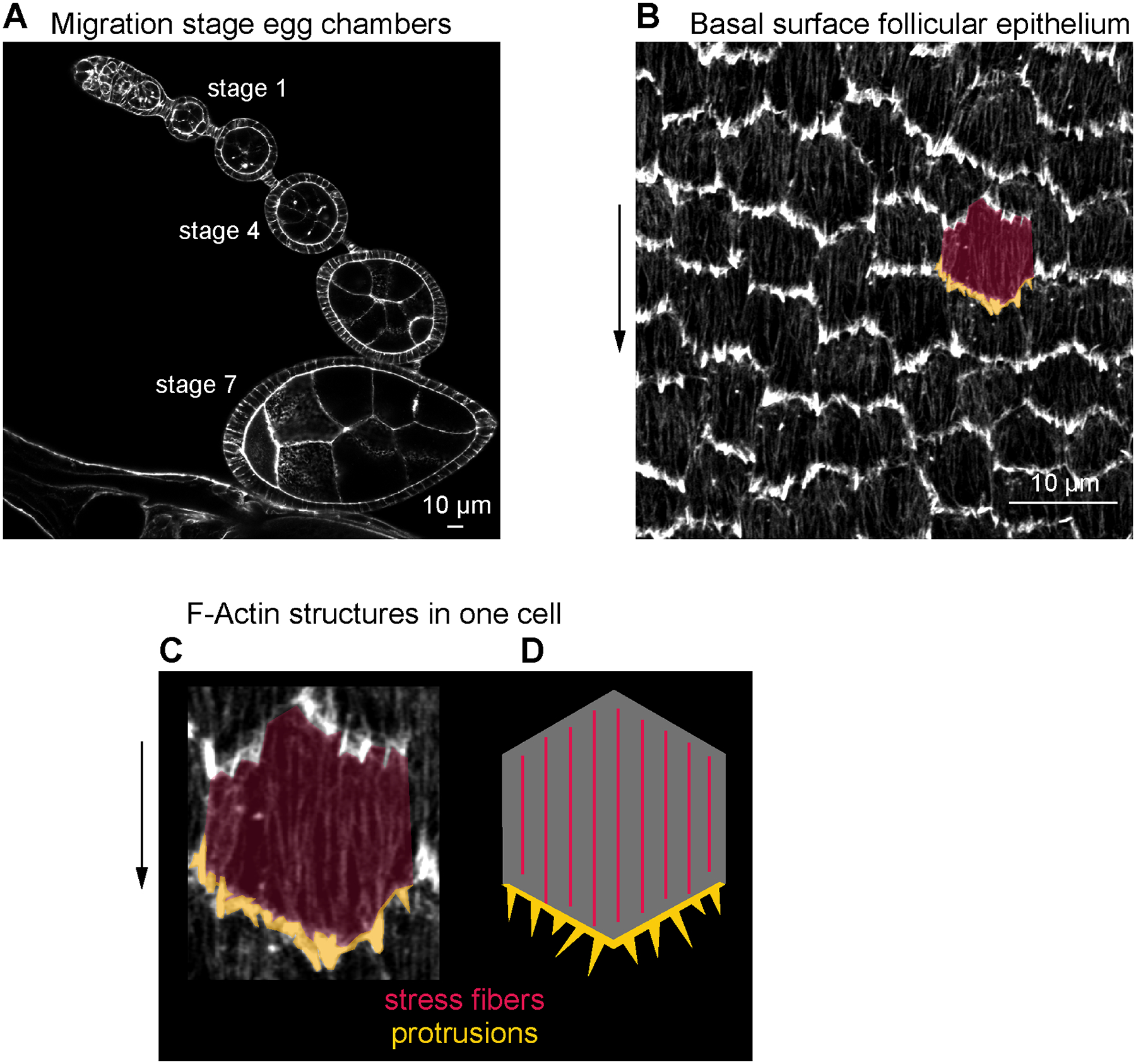
(a) Image of the basal surface of the follicular epithelium at stage 4. (b) Image of the basal surface of the follicular epithelium at stage 7. (c) Image of one follicle cell from (b), highlighting leading-edge protrusions (gold) and stress fibers (red). (d) Image of a transverse section through a developmental array of egg chambers at stages when the follicular epithelium is migrating.
The follicular epithelium is part of a larger multicellular structure called the egg chamber, which is the precursor to the egg [11]. Each egg chamber is composed of an inner germ cell cyst, consisting of 15 nurse cells and 1 oocyte, which is surrounded by the somatic follicular epithelium, also called “follicle cells,”. The follicle cells are arranged with the apical surfaces contacting the germ cells and their basal surfaces facing outwards. This entire structure is encapsulated by a basement membrane extracellular matrix. Egg chambers progress through 14 developmental stages, starting as a spherical shape and ending as a highly elongated shape (see Fig. 1d). From stage 1 or 2 through stage 8, the follicle cells collectively migrate on the basement membrane, and this motion is required to lengthen the egg chamber [3,12,13]. Because the basal surfaces of the follicle cells face outward, the F-actin structures powering their migration are located close to the coverslip in slide-mounted samples, facilitating high-resolution imaging.
Although this chapter focuses on the preservation and phalloidin staining of F-actin structures in migration-stage egg chambers, the protocol is also compatible with other experimental goals. First, with minor adjustments to the tissue dissection technique, the protocol is also useful for visualizing follicle cell stress fibers in post-migratory-stage egg chambers. Second, co-visualization of basal F-actin networks and fluorescently-tagged proteins is readily achievable, and we provide corresponding guidance on the uses of different phalloidin conjugates, which will vary based on the fluorescent tags present. However, to obtain the highest quality images of the basal F-actin networks, we do not recommend co-staining with antibodies, as this weakens the phalloidin signal. If you do combine this protocol with immunofluorescence, performing antibody staining followed by phalloidin staining yields the best results.
We have previously published a chapter in Methods in Molecular Biology on live imaging of follicle cell migration [14]. The protocol for dissection is shared between these chapters, and the chapter by Zajac et al., on flow chambers in the current edition, and sections are duplicated here for convenience. We refer the reader to the live imaging chapter for detailed images and movies of the egg chamber dissection process, which are not included here.
2. Materials
2.1. Preparing Female Flies for Dissection
Vials with fly food.
Yeast powder, dry active yeast ground to a fine powder in coffee grinder.
2.2. Egg Chamber Dissection
Pen/Strep: penicillin G-sodium 10,000 U/ml, streptomycin sulfate 10,000 μg/ml in 0.85% saline.
Acidified water: 1 μl concentrated (12.1 N) HCl in 1 ml deionized water.
Insulin: 1 mg dissolved in 100 μl acidified water (see Note 1).
Live imaging medium [15]: Schneider’s S2 medium, 0.6X Pen/Strep, 15% vol/vol fetal bovine serum, 0.1 mg/ml insulin (see Note 2).
Pyrex 9-Cavity Spot Plate.
Dumont forceps: #5, 0.1 × 0.06 mm tip, and #55, 0.05 × 0.02 mm tip (see Note 3).
Eyelash tool: insert an eyelash into a slightly melted p1000 pipettor tip.
Disposable needle, 27G × ½ in.
Glass pasteur pipets, 5 ¾ in.
5 ml pipet pump.
Stereomicroscope with magnification of at least 10X.
CO2 pad to anesthetize flies.
2.3. Fixation, Staining, and Mounting
Phosphate buffered saline (PBS): 137 mM NaCl, 2.7 mM KCl, 10 mM Na2HPO4, 1.8 mM KH2PO4.
Phosphate buffered saline + Triton X-100 (PBT): Phosphate buffered saline, 0.1% vol/vol Triton X-100.
16% EM grade formaldehyde (see Note 4).
1.5 ml microfuge tubes.
p10 pipettor.
p10 pipettor tips.
Glass pasteur pipets, 5 ¾ in.
5 ml pipet pump.
Alexa Fluor™ 488-, Alexa Fluor™ 555-, or Alexa Fluor™ 647-phalloidin (see Fig. 2 and caption for a comparison of their relative staining quality).
Nutating mixer.
Liquid mounting medium (see Note 5).
Glass microscope slide, 3” × 1” × 1 mm.
Coverslip, 22 mm × 50 mm #1.5.
Nail polish.
Figure 2. Comparison of different fluorophore conjugates of phalloidin.
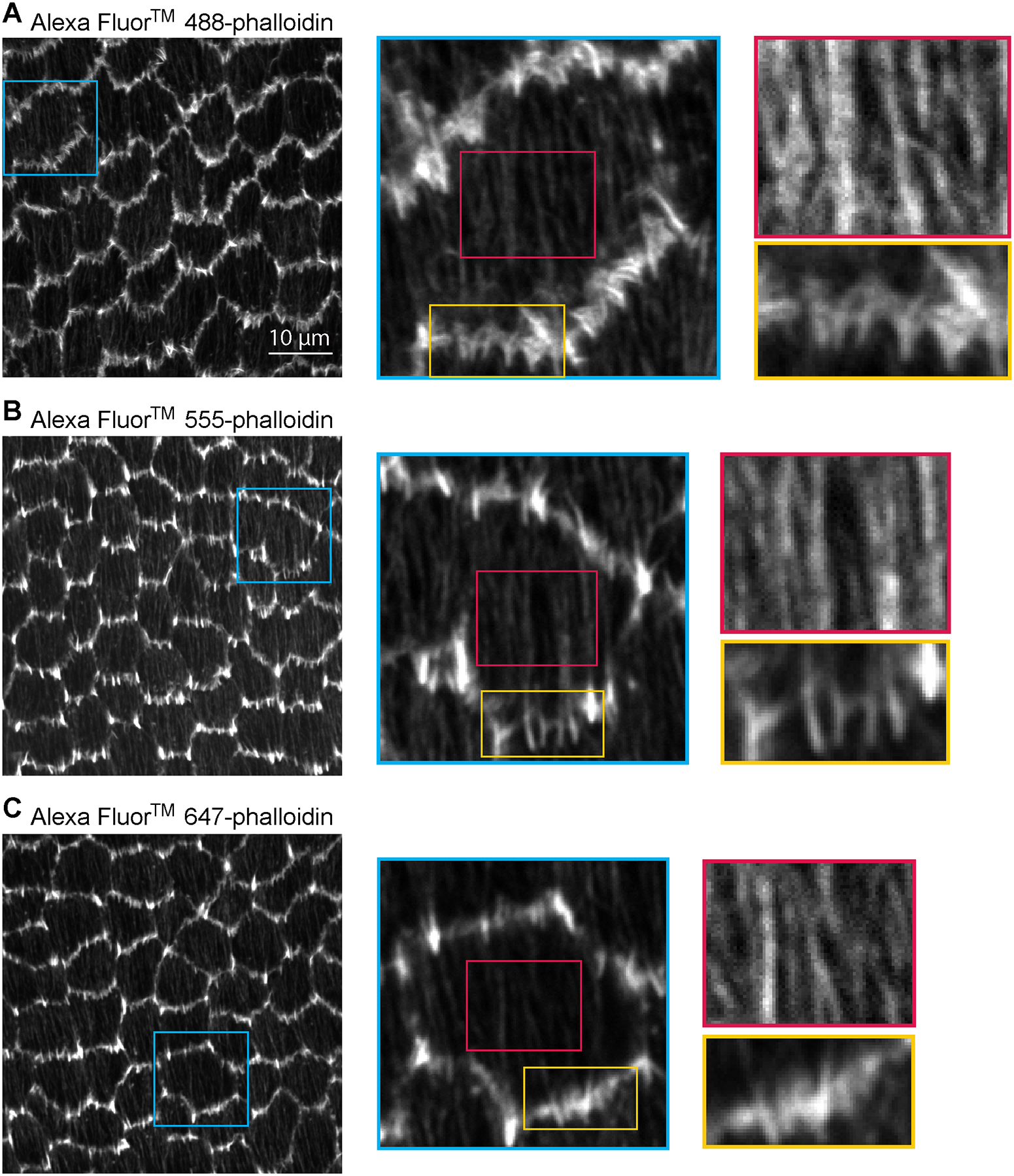
Images of (a-c) Alexa Fluor™ 488-phalloidin, (d-f) Alexa Fluor™ 555-phalloidin, and (g-i) Alexa Fluor™ 647-phalloidin staining at the basal surface of the follicular epithelium of a stage 8 egg chamber. (a) Image of Alexa Fluor™ 488-phalloidin staining of a field of follicle cells. (b) Zoom-in of an individual cell in the blue boxed region of (a). (c) Gold and red rectangles show a zoom-in of leading edge protrusions and stress fibers, respectively, in the boxed regions of (b). (d) Image of Alexa Fluor™ 555-phalloidin staining of a field of follicle cells. (e) Zoom-in of an individual cell in the blue boxed region of (d). (f) Gold and red rectangles show a zoom-in of leading edge protrusions and stress fibers, respectively, in the boxed regions of (e). (g) Image of Alexa Fluor™ 647-phalloidin staining of a field of follicle cells. (h) Zoom-in of an individual cell int eh blue boxed region of (g). (i) Gold and red rectangles show a zoom-in of leading edge protrusions and stress fibers, respectively, in the boxed regions of (h). Brightness is increased specific to each image in red boxes to better show stress fibers (c, f, i). All images were taken with a 63× 1.4 NA Plan Apochromat oil lens, a digital zoom of 1x, and the pinhole set to 1 Airy Unit. Detailed images in colored boxes are shown scaled by pixel number to illustrate how fluorophore wavelength affects the maximum resolution that can be achieved. Resolution of images in left-most column: (a) 13.4493 pixels/μm. (d) 12.1642 pix/μm. (g) 11.4424 pix/μm.
2.4. Imaging
Confocal microscope with high resolution objectives
3. Methods
3.1. Preparing Female Flies for Dissection
Sprinkle yeast powder on fly food in a vial, covering about one half of the surface. Add up to six 1–2 day old females and at least 1–2 young males to the vial. Yeast is essential for proper egg chamber production. Incomplete nutrition will slow egg chamber production by inducing cell death in the germarium and in stage 8 egg chambers [16–18].
Age females for 1–3 days. Move flies to a new vial with fresh yeast every two days before dissection (see Note 6).
3.2. Reagent Preparation
Prior to dissection, add 500 μl of live imaging medium to a well of a Pyrex 9-Cavity Spot Plate. Use a separate well of live imaging medium for each genotype you are dissecting. Allow medium to come to room temperature prior to dissection.
Prepare 300 μl of fixative in a microfuge tube by diluting EM grade formaldehyde in PBT to 4% vol/vol. Allow to come to room temperature.
Prepare 25–150 μl of staining solution in a microfuge tube by diluting phalloidin in PBT to the following specified concentrations: Alexa Fluor™ 488-phalloidin at 1:200, Alexa Fluor™ 555-phalloidin at 1:300, Alexa Fluor™ 647-phalloidin at 1:50 (see Note 7). Protect the tube from ambient light by wrapping in foil or placing in a drawer.
3.3. Egg Chamber Dissection
In this section we describe how to isolate egg chambers from the ovary, which requires a basic understanding of the ovary’s structure. We also provide some guidance on potential reasons for isolating egg chambers of a given stage. We refer the reader to our previous chapter in Methods in Molecular Biology on live imaging of follicle cell migration for detailed images and movies of the egg chamber dissection process [14].
Each ovary is composed of 15–18 developmental arrays of egg chambers called ovarioles. At the anterior of each ovariole is the germarium, the site of egg chamber production. Moving posteriorly are successively older egg chambers, each connected to one another like beads on a string by stalk cells. At the posterior of each ovariole are the oldest egg chambers or mature eggs waiting to be laid. Each ovariole, as well as the entire ovary, is surrounded by a muscle sheath that will need to be removed during dissection. Egg chambers can be staged by eye based on both their overall size and shape, as well as the relative size and shape of the oocyte. Older egg chambers are also distinguished by their partly opaque appearance, due to the onset of vitellogenesis at stage 8.
Based on your experimental goals, you may choose egg chambers of various stages to dissect. Although stage 7 and 8 egg chambers have the most prominent and easily identifiable protrusions, protrusions are present in younger egg chambers as well if you wish to focus on earlier stages of follicle cell migration (see Fig. 1d). Dissection technique varies based on which stage egg chambers you wish to collect, and dissection will damage egg chambers of other stages, so do not attempt to collect egg chambers of stages for which your dissection is not optimized.
Finally, we caution that the entire dissection process described below should not last longer than 10 minutes, as the preservation of dynamic F-actin structures is improved if egg chambers are quickly moved into fixative following their removal from the female.
Position a spot plate well containing live imaging medium underneath microscope. Adjust magnification to 10X-16X and focus to the bottom of the well.
Dissect ovaries from female flies. First, anesthetize the flies with CO2. Using the #5 forceps in your non-dominant hand, pinch a female fly at the anterior-most part of her abdomen (see Note 8). While still pinching, transfer the fly to the live imaging medium and completely submerge. Using the #55 forceps in your dominant hand, pinch the abdomen between the two posterior-most segments and pull posteriorly. The ovaries should release from the abdomen (if ovaries do not release, see Note 9). Remove all non-ovary tissue from the well. To obtain stage 1–5 egg chambers, see step 3. To obtain stage 5–8 egg chambers, see step 4.
To obtain stage 1–5 egg chambers, pinch the posterior of an ovary with the #5 forceps and pin it to the bottom of the well. Use the #55 forceps to pinch a single ovariole just anterior to where the ovary is pinned. Pull the ovariole orthogonally and then anteriorly to remove it from the muscle sheath and isolate it from the ovary. Ovarioles that have been removed from their muscle sheaths will look and move like beads on a string, rather than like a single packaged unit. Repeat this process until ovarioles do not easily separate from the ovary, as repeated pulling risks damaging egg chambers. Repeat for the second ovary.
To obtain stage 5–8 egg chambers, pinch the posterior of an ovary with the #5 forceps and pin it to the bottom of the well. Use the #55 forceps to pinch single ovarioles at the anterior tip of the ovary and pull anteriorly to remove ovarioles from their muscle sheaths and isolate them from the ovary. Ovarioles that have been removed from their muscle sheaths will look and move like beads on a string, rather than like a single packaged unit. Repeat this process until ovarioles do not easily separate from the ovary, as repeated pulling risks damaging egg chambers. Repeat for the second ovary.
Repeat steps 2–5 as necessary to achieve a desired number of egg chambers for a given stage, typically 10–20 ovarioles. Fixing too many ovarioles in a single microfuge tube could limit penetration of the phalloidin stain. Be aware during dissection of any damaged egg chambers or other tissues and isolate them in another part of the dish away from healthy egg chambers. Damaged tissues in the vicinity of undamaged egg chambers can lower staining quality.
Separate healthy ovarioles from unwanted material using an eyelash tool. Do not take ovarioles that retained their muscle sheaths, as this actin-rich tissue will prevent visualization of the F-actin structures at the basal epithelial surface. If you are attempting to gather pre-stage 5 egg chambers, trim ovarioles containing egg chambers older than stage 5 by placing the needle on the stalk after the stage 5 egg chamber and pressing down using a slicing motion. Older egg chambers will prevent the compression of younger egg chambers under the coverslip and thereby reduce the area of the basal surface available for imaging. If you are imaging older egg chambers, trimming is usually unnecessary.
Gather the trimmed ovarioles in the center of the well with the eyelash tool.
3.4. Fixation, Staining, and Mounting
Using a p10 or fitted with a p10 pipettor tip, transfer egg chambers from the well to fixative in as little live imaging medium as possible to avoid diluting the fixative (see Note 10).
Fix egg chambers for 15 min at room temperature without rocking. Avoid fixing for any longer, as over fixation can reduce penetration of the phalloidin stain.
Using a 5 ml pipet pump fitted with a glass pasteur pipet, remove as much fixative as possible from the microfuge tube without removing the egg chambers. Wash egg chambers 3x with 500 μl PBT for 5 min each at room temperature without rocking, removing and replacing each wash (see Note 11).
After the final wash, remove PBT with the glass pasteur pipet and pipet pump (see Note 12). Add the prepared phalloidin staining solution and allow the egg chambers to stain for the following times based on your conjugated fluorophore: Alexa Fluor™ 488-phalloidin or Alexa Fluor™ 555-phalloidin, 15 minutes at room temperature without rocking; Alexa Fluor™ 647-phalloidin, 2 hours at room temperature, rocking on nutator, covered in foil to prevent bleaching from exposure to ambient light.
Using the glass pasteur pipet and pipet pump, remove the phalloidin solution and replace with 500 μl PBT. Wash 3x with 500 μl PBT for 5 min each at room temperature without rocking, removing and replacing each wash.
After removing the final wash, add 35 μl of mounting medium to the microfuge tube (see Note 13).
Using the glass pasteur pipet and pipet pump, remove mounting medium and egg chambers from microfuge tube and deposit on the glass slide, moving horizontally to create a single line of medium. Ensure the line of medum is shorter than the cover slip. Apply the coverslip to the slide (see Note 14).
Apply a small amount of nail polish to each corner of the coverslip and allow to dry for a few minutes to stabilize the coverslip position. Apply a small amount of nail polish to each edge of the coverslip without gaps and allow to dry. Store the slide horizontally at 4 °C until ready for imaging.
3.5. Imaging
In this section, we provide brief tips on image acquisition of basal actin structures using confocal microscopy. This is not intended to be a comprehensive protocol but to describe aspects of the process that are important for capturing high quality images. The main issue faced in imaging middle to late migration stages (stages 5 to 8) is that the protrusive F-actin structures are extremely bright compared to the stress fibers. Thus, the challenge is to image the brightest structures accurately, while still collecting adequate information from the dimmer structures. Although it is not necessary to optimize all the settings discussed below for every image, it is advantageous to understand the elements of image collection, where introduction of noise can best be minimized, and wherein the limits of achieving maximal resolution lie. We use a Zeiss LSM 800 upright scanning confocal microscope controlled with Zen 2.3 Blue acquisition software (Zeiss) for imaging for imaging, though the steps described below are broadly applicable to other confocal systems.
Choose the objective with the best resolving power available on your microscope, as determined by numerical aperture (NA) written on the lens. Higher NA equals higher resolving power. If you are imaging two or more colors, apochromat lenses ensure the wavelengths are properly aligned in the same z-plane. If imaging a single color, fluor or achromat lenses are also fine.
Scan at a fast speed to get the area of interest in approximate focus, then use a slow scan speed to fine-tune the focus.
Select the excitation spectra in your software that best matches the excitation and emission wavelengths of your fluorophore. For example, 488 can differ from EGFP on many systems.
Set data collection to 16-bit; this will give a greatly expanded dynamic range that preserves information from the dimmer structures while maintaining reasonable pixel intensity of the brightest structures (see Note 15). If data is collected at 8 bits, much information about the dimmer structures will be lost.
Set the gain as low as possible to reduce the noise in the image.
Adjust the laser power so that it is just high enough that most of the dynamic range is used, without oversaturating any pixels. Most microscopes have software tools to check for range and oversaturation.
If you wish to obtain the maximum possible z-resolution for the lens and fluorophore you are using, set the pinhole to 1 Airy unit (software option available on most systems). This will be smaller for higher NA lenses and shorter fluorophore wavelengths, meaning for the same 63x lens a z-section of 0.7 μm can be resolved for Alexa Fluor™ 488-phalloidin, but this expands to 0.9 μm for Alexa Fluor™ 647-phalloidin. Note that (within reasonable parameters) the pinhole size does not affect the x-y resolution. Setting the pinhole to a larger diameter than 1 Airy unit can sometimes be advantageous, as it lets in more light and includes structures from a slightly thicker plane. In contrast, setting the pinhole smaller than 1 Airy unit presents no advantages.
To obtain the maximum x-y resolution possible with a given combination of fluorophore, lens, and digital zoom, choose the appropriate number of pixels per μm to sample. Most microscopes contain software settings to select the maximum number of pixels for a given set of conditions. Over-collecting pixels does no harm other than using more microscope time and requiring more storage space for the resulting images, as phalloidin is not prone to rapid bleaching. Under-collecting pixels, however, will needlessly reduce your image quality. See Fig. 2 for illustration of how wavelength limits maximum resolution for three different fluorophore conjugates of phalloidin. Shorter wavelengths give higher pixel resolution; however, a very nice stain can be obtained with Alexa Fluor™ 647-phalloidin.
Center the area of interest and increase the digital zoom to the desired magnification.
Orient the egg chamber such that its anterior-posterior axis is horizontal in the field of view by rotating the stage either manually or virtually. This prevents having to rotate the image later by an increment other than 90 degrees, which requires either resampling the pixels (considered undesirable in many contexts) or reducing the resolution substantially.
Scan at a sufficiently slow speed that noise is not introduced at this step (e.g., for a 743×743 pixel image, a pixel dwell time of 10 μs or longer is preferable; see Note 16).
4. Notes
Insulin solution can be stored at 4 °C for up to one week. Insulin solution should be added to the live imaging medium immediately before use.
Schneider’s S2 medium and Pen/Strep can be combined and stored at 4 °C. Fetal bovine serum can also be combined with the Schneider’s S2 medium and Pen/Strep mixture and stored at 4 °C for up to one week. We make 10 ml of the S2, Pen/Strep, and fetal bovine serum mixture at a time.
To minimize tissue damage, maintain forceps with care and sharpen as needed.
We dilute methanol-free EM-grade formaldehyde in PBT. Formaldehyde should be stored at 4°C for no more than one week after an ampule is opened and should be added to PBT immediately before use.
Mounting medium that hardens will cause cracking of the egg chamber, so it is best to use a mounting medium that remains liquid.
Depending on the genotype, age, and temperature, the rate of oogenesis may vary, and flies may need to be aged for different numbers of days to achieve an optimal number of egg chambers of your desired stage for dissection. Younger females produce more eggs than older females, colder temperatures slow oogenesis, and warmer temperatures speed oogenesis. Flies must be moved to fresh yeast regularly or females will cease laying eggs and retain them in their ovaries, resulting in unhealthier egg chambers and fewer younger egg chambers. Certain genetic conditions can result in round eggs which will block the oviduct, which results in unhealthy egg chambers; dissecting younger flies prior to oviduct blockage is often useful in these backgrounds.
To minimize the amount of phalloidin used, we typically prepare a volume of staining solution such that 0.5 μl of phalloidin will be diluted to the correct concentration.
Proper pinching of the fly will ensure the rest of your dissection proceeds smoothly. Pinching the thorax increases the risk that attempting to open the abdomen to remove the ovaries will instead remove the entire abdomen without opening it. Pinching a more posterior part of the abdomen increases the risk that you will damage young egg chambers.
If the ovaries do not initially release from the abdomen, there are several methods to remove them. If the oviduct is visible, first attempt to tug posteriorly on the oviduct with your #55 forceps to remove the ovaries, as this is the least likely method to damage egg chambers. If the oviduct is not visible or tugging did not work, there are two other options. If late-stage egg chambers are desired, the abdomen can be gently squeezed like a tube of toothpaste in an anterior-to-posterior direction to extrude the ovaries. If younger egg chambers are desired, the posterior of the ovaries can be pulled on directly. We recommend practicing dissections as more maneuvers to remove the ovaries increases the likelihood of damage.
A p20 pipettor could also be used in lieu of a p10 pipettor.
Ovarioles will sink to the bottom of the tube; removing most but not all of the liquid will ensure that ovarioles are not also removed. Ensure the first wash does not proceed for longer than 5 minutes, as some residual formaldehyde will remain after removal of the fixative and could result in over fixation.
If antibody staining is being combined with phalloidin staining, antibody staining should be performed at this step, and followed with phalloidin staining as described by the subsequent steps of this protocol.
Remove as much wash as possible without removing the ovarioles. Remaining wash will dilute the mounting medium.
To apply the coverslip, our preferred method to avoid introducing air bubbles is to first place the short end of the coverslip on the glass slide. Then, using a p10 pipet tip, gently lower the other end of the coverslip to the glass slide, and pull the pipet tip out from under the cover slip once the tip is in contact with the glass slide. Other methods for applying the coverslip are acceptable, provided that air bubbles are kept to a minimum. If any mounting medium spills out from under the coverslip, it can be removed by gently dabbing with the edge of a Kimwipe. Excess liquid can make it difficult to seal the coverslip with nail polish. Be cautious not to remove too much medium, however, as this insufficient medium can result in cracking of egg chambers due to pressure from the cover slip.
Dimmer structures can be highlighted in post-processing using various means such as alternate look-up tables or inversion in Fiji/ImageJ before the image is set to 8-bit for use in figures.
If you are co-imaging another label like GFP, it is often preferable to use Alexa Fluor™ 647-phalloidin, as this allows good separation of excitation and emission spectra to avoid issues of bleed-through. Alexa Fluor™ 647-phalloidin is also inherently dimmer than Alexa Fluor™ 488- or Alexa Fluor™ 555-phalloidin, which can help avoid bleed-through from the shorter wavelengths.
Acknowledgements
We thank members of the Horne-Badovinac lab for helpful comments on the protocol. M.T.A. was supported by NIH T32 GM007183 and work in the Horne-Badovinac lab is supported by NIH R01s GM126047 and GM136961.
References:
- 1.Friedl P, Gilmour D (2009) Collective cell migration in morphogenesis, regeneration and cancer. Nat Rev Mol Cell Biol 10(7):445–457. doi: 10.1038/nrm2720 [DOI] [PubMed] [Google Scholar]
- 2.Mayor R, Etienne-Manneville S (2016) The front and rear of collective cell migration. Nat Rev Mol Cell Biol 17(2):97–109. doi: 10.1038/nrm.2015.14 [DOI] [PubMed] [Google Scholar]
- 3.Cetera M, Ramirez-San Juan GR, Oakes PW, Lewellyn L, Fairchild MJ, Tanentzapf G, Gardel MG, Horne-Badovinac S (2014) Epithelial rotation promotes the global alignment of contractile actin bundles during Drosophila egg chamber elongation. Nat Comm 5:5511. doi: 10.1038/ncomms6511 [DOI] [PMC free article] [PubMed] [Google Scholar]
- 4.Gutzeit HO (1991) Organization and in vitro activity of microfilament bundles associated with the basement membrane of Drosophila follicles. Acta Histochem Suppl 41:201–210 [PubMed] [Google Scholar]
- 5.Gutzeit HO, Eberhardt W (1991) Laminin and basement membrane-associated microfilaments in wild-type and mutant Drosophila ovarian follicles. J Cell Sci 100(4):781–788. doi: 10.1242/jcs.100.4.781 [DOI] [PubMed] [Google Scholar]
- 6.Gutzeit HO (1990) The microfilament pattern in the somatic follicle cells of mid-vitellogenic ovarian follicles of Drosophila. Eur J Cell Biol 53(2):349–356 [PubMed] [Google Scholar]
- 7.Sherrard KM, Cetera M, Horne-Badovinac S (2021) DAAM mediates the assembly of long-lived, treadmilling stress fibers in collectively migrating epithelial cells in Drosophila. eLife 10:e72881. doi: 10.7554/eLife.72881 [DOI] [PMC free article] [PubMed] [Google Scholar]
- 8.Bateman J, Reddy RS, Saito H, Van Vactor D (2001) The receptor tyrosine phosphatase Dlar and integrins organize actin filaments in the Drosophila follicular epithelium. Curr Biol 11(17):1317–1327. doi: 10.1016/S0960-9822(01)00420-1 [DOI] [PubMed] [Google Scholar]
- 9.Delon I, Brown NH (2009) The integrin adhesion complex changes its composition and function during morphogenesis of an epithelium. J Cell Sci 122(23):4363–4374. doi: 10.1242/jcs.055996 [DOI] [PMC free article] [PubMed] [Google Scholar]
- 10.Spracklen J, Fagan TN, Lovander KE, Tootle T (2014) The pros and cons of common actin labeling tools for visualizing actin dynamics during Drosophila oogenesis. Dev Biol 393(2):209–226. doi: 10.1016/j.ydbio.2014.06.022 [DOI] [PMC free article] [PubMed] [Google Scholar]
- 11.Horne-Badovinac S, Bilder D (2005) Mass transit: Epithelial morphogenesis in the Drosophila egg chamber. Dev Dyn 232(3):559–574. doi: 10.1002/dvdy.20286 [DOI] [PubMed] [Google Scholar]
- 12.Haigo SL, Bilder D (2011) Global Tissue Revolutions in a Morphogenetic Movement Controlling Elongation. Science 331(6020):1071–1074. doi: 10.1126/science.1199424 [DOI] [PMC free article] [PubMed] [Google Scholar]
- 13.Horne-Badovinac S (2014) The Drosophila Egg Chamber—A New Spin on How Tissues Elongate. Integr Comp Biol 54(4):667–676. doi: 10.1093/icb/icu067 [DOI] [PMC free article] [PubMed] [Google Scholar]
- 14.Cetera M, Lewellyn L, Horne-Badovinac S (2016) Cultivation and Live Imaging of Drosophila Ovaries. In: Dahmann C (ed) Drosophila. Methods in Molecular Biology, vol 1478. Humana Press, New York, NY, pp 215–226 [DOI] [PubMed] [Google Scholar]
- 15.Prasad M, Jang AC-C, Starz-Gaiano M, Melani M, Montell DJ (2007) A protocol for culturing Drosophila melanogaster stage 9 egg chambers for live imaging. Nat Protoc 2(10):2467–2473. doi: 10.1038/nprot.2007.363 [DOI] [PubMed] [Google Scholar]
- 16.Drummond-Barbosa D, Spradling AC (2001) Stem cells and their progeny respond to nutritional changes during Drosophila oogenesis. Dev Biol 231(1):265–278. doi: 10.1006/dbio.2000.0135 [DOI] [PubMed] [Google Scholar]
- 17.Mazzalupo S, Cooley L (2006) Illuminating the role of caspases during Drosophila oogenesis. Cell Death Differ 13(11):1950–1959. doi: 10.1038/sj.cdd.4401892 [DOI] [PubMed] [Google Scholar]
- 18.Pritchett TL, Tanner EA, McCall K (2009) Cracking open cell death in the Drosophila ovary. Apoptosis 14(8):969–979. doi: 10.1007/s10495-009-0369-z [DOI] [PMC free article] [PubMed] [Google Scholar]