

Significance
Mucus conditions are important biomarkers for indicating inflammation and stent patency inside the human airway but remain challenging to monitor. Existing methods pose risks due to radiation exposure and lack the ability to provide continuous real-time feedback outside of hospital settings. Inspired by the sensing ability of biological cilia, we report wireless sensing mechanisms in sensory artificial cilia for detecting mucus conditions, including viscosity and layer thickness, which are crucial biomarkers for disease severity. The proposed sensing mechanisms in artificial cilia allow continuous monitoring of the properties of biofluids inside the airway. These sensing mechanisms could be integrated with existing implantable devices, such as airway stents, to monitor various fluidic conditions for disease monitoring, enabling timely interventions.
Keywords: artificial cilia, lung, airway stent, magnetic actuation, mucus sensing
Abstract
Continuously monitoring human airway conditions is crucial for timely interventions, especially when airway stents are implanted to alleviate central airway obstruction in lung cancer and other diseases. Mucus conditions, in particular, are important biomarkers for indicating inflammation and stent patency but remain challenging to monitor. Current methods, reliant on computational tomography imaging and bronchoscope inspection, pose risks due to radiation and lack the ability to provide continuous real-time feedback outside of hospitals. Inspired by the sensing ability of biological cilia, we report wireless sensing mechanisms in sensory artificial cilia for detecting mucus conditions, including viscosity and layer thickness, which are crucial biomarkers for disease severity. The sensing mechanism for mucus viscosity leverages external magnetic fields to actuate a magnetic artificial cilium and sense its shape using a flexible strain-gauge. Additionally, we report an artificial cilium with capacitance sensing for mucus layer thickness, offering unique self-calibration, adjustable sensitivity, and range, all enabled by external magnetic fields. To enable prolonged and wireless data access, we integrate Bluetooth Low Energy communication and onboard power, along with a wearable magnetic actuation system for sensor activation. We validate our method by deploying the sensor independently or in conjunction with an airway stent within a trachea phantom and sheep trachea ex vivo. The proposed sensing mechanisms and devices pave the way for real-time monitoring of mucus conditions, facilitating early disease detection and providing stent patency alerts, thereby allowing timely interventions and personalized care.
Airway stents (1, 2) play an essential role for addressing diseases like central airway obstruction (3), as seen in conditions such as lung cancer, wherein the airway narrows from extrinsic compression. They are hollow, cylindrical tubes to provide crucial radial support (4), alleviating the effects of airway obstruction (2). However, a drawback of current airway stents is their interference with airway cilia, microscopic structures responsible for mucus transport (5), leading to mucus build-up. The accumulation of thick mucus in the airways poses challenges for patients by obstructing breathing and inducing inflammation, resulting in unpredictable episodes of airway distress and urgent bronchoscopy in cases of excessive mucus accumulation (6).
The properties of mucus such as viscosity and volume serve as important indicators of airway health and stent patency (7). For example, mucus viscosity reflects inflammation triggered by bacteria and other antigens (8) and the resulting viscous mucus could impede mucociliary transport and elicit airway obstruction. Meanwhile, the amount of mucus in the airway stent is crucial for determining further interventions as excessive mucus causes the clogging of the airway. Previous monitoring methods have relied on scheduled medical imaging checks such as computational tomography (9, 10) which has radiation, is expensive, and must be performed in hospitals, and thus cannot provide continuous sensing. In addition, bronchoscopy (11, 12) is used for follow-up stent patency check but requires anesthesia and cannot provide continuous monitoring, either.
On one hand, monitoring mucus conditions by integrating sensors on implantable devices is a potential solution to allow continuous monitoring of the airway conditions and stent patency. Conventional stents, typically composed of inert materials such as silicone or metal, lack integrated sensors to monitor physiological conditions within the airway (13), constraining their effectiveness for both disease management and device monitoring. Existing efforts of integrating sensors on implantable devices inside the lumen of the human body have mostly focused on vascular (14) and esophageal stents (15). These sensor technologies have yet to be implemented in airway devices.
On the other hand, the lack of sensing mechanisms for wireless monitoring mucus conditions also prevents sensing mucus properties in the airway for patients with airway stents. First, previous efforts have predominantly focused on in vitro sensing (16), which are unsuitable for continuous long-term monitoring. Second, existing wireless devices used on the skin (17–21) provide long-term monitoring functions of the airway by sensing the vibration during breathing, but they cannot easily monitor the physiological conditions inside the airway. Last, existing implantable sensors (22) have demonstrated detecting temperature, flow, and pressure (23, 24), but the capability to assess mucus viscosity or volume is still missing. Previous research has explored integrating sensors into airway stents for assessing air flow and stent patency (25, 26), but these devices have issues of being bulky for long-term use due to their tethered nature. Therefore, it remains a grand challenge to develop miniature sensors for sensing mucus viscosity and volume continuously inside the airway.
Inspired by the sensing ability of biological cilia, we report wireless sensing mechanisms in sensory artificial cilia for detecting mucus conditions, including viscosity and layer thickness. First, we propose a mechanism for artificial cilia to sense the viscosity of mucus (non-Newtonian) through fluid–structure interaction, implementing this mechanism on magnetically actuated artificial cilia with integrated flexible sensors. Second, we propose a sensing mechanism for artificial cilia to sense the layer thickness of biofluids with self-calibration, as well as reconfigurable sensitivity and range. The sensitivity and range of this sensor are adjusted by varying the angle of the external magnetic field. Third, to enable prolonged and wireless data access, we integrate Bluetooth Low Energy (BLE) communication and onboard power, and create a wearable magnetic actuation system for actuating the sensors. Last, we validate our method by deploying the sensor independently or in conjunction with an airway stent within a trachea phantom and ex vivo sheep trachea. We demonstrate the ability to sense porcine mucus conditions using these sensory artificial cilia when integrated with versatile airway stents, which are widely used in various lung diseases leading to central airway obstruction. This real-time assessment of lung physiological conditions provides healthcare professionals with invaluable data, empowering them to make well-informed decisions regarding patient care.
Results
Working Principle of Sensory Artificial Cilia in an Airway Stent.
Artificial cilia have been reported with promising fluid manipulation functions (27–29) at millimeter and micrometer scales. While integrating artificial cilia in airway stents has shown mucus transportation through fluid–structure interaction (26, 27), sensing mucus properties remains limited. As shown in Fig. 1A, we propose a cilia-inspired sensory device for sensing airway mucus conditions, which includes onboard sensors, data processing and transmission units, and a power module. As shown in Fig. 1B, our device can be integrated with an airway stent to continuously monitor advanced mucus conditions such as viscosity and layer thickness inside the human central airway, which are important biomarkers for disease diagnosis and stent patency monitoring. In addition to the onboard components, an external magnetic field, generated by a lightweight wearable system, plays a key role in enabling advanced sensing functions. Please refer to Demonstration of Integration with Airway Stents and Sensing Mucus Properties for details.
Fig. 1.

Overview of the sensory artificial cilia for monitoring the conditions of airway stents and the airway. (A) Concept of the proposed device for monitoring airway mucus conditions inside a human trachea actuated by external magnetic fields. (B) Illustration of the viscosity and layer thickness sensors for sensing mucus properties. (C) Illustration of sensor signal outputs for liquids of different viscosities. (D) Illustration of the layer thickness sensor for sensing liquid layer thickness. (E) Illustration of system electronic components and connections. (F) Optical image of the electronic components of the sensory ring. The components include a BLE System-on-a-Chip, two coin-batteries, a viscosity sensor, a layer thickness sensor, and a magnetic sensor (with a temperature sensor inside). (G) Optical image of the electronic components of the sensory ring with a flexible backlayer made of Thermoplastic polyurethane (TPU). (H) The data flow chart of the electronic system and illustration of the user interface. (I) Optical image of a sensory ring and a hybrid airway stent integrated together for sensing mucus properties.
Fig. 1C illustrates the mechanism for sensing mucus viscosity of an artificial cilium. Inspired by biological cilia, the artificial cilium made of a magnetic composite dynamically interacts with the surrounding liquid when a rotating magnetic field is applied. The motion of the sensor is more obvious in a less viscous fluid when actuated by the same rotating magnetic field. Consequently, as shown in Fig. 1C, fluid viscosity can be interpreted from the deformation of the artificial cilium, estimated using the electrical resistance of a flexible strain-gauge produced by patterning laser-induced graphene (LIG). In addition, Fig. 1D shows the mucus layer thickness sensor and the mechanism for sensing mucus layer thickness by measuring the mucus-level-dependent capacitance of a patterned capacitor. With the two conductive traces patterned parallel to each other with a narrow gap in between, the sensor’s capacitance depends on the length of the gap filled by mucus. The mucus layer thickness is subsequently calibrated and measured by the sensor’s capacitance using onboard circuits. The flexible hinge of the capacitor allows the sensor to be tilted remotely by magnetic fields such that the sensitivity and sensing range of the layer thickness sensor can be reconfigured on-demand by applying an external magnetic field.
The device is supported by wireless communication and onboard power. To enable wireless communication, Fig. 1E illustrates the sensor patch, which includes the BLE System-on-a-Chip (SoC), the magnetic sensor, and connection ports to the power source and sensors. The sensor patch is prepared by laser-patterning a flexible circuit on Pyralux, fully encapsulated in Polyimide (PI) for electrical insulation and biocompatibility. Fig. 1F shows the patch with integrated chips, peripheral circuits, and batteries, featuring the viscosity sensor, layer thickness sensor, magnetic sensor, and temperature sensor. The patch is attached to a Thermoplastic polyurethane (TPU) flexible ring as a backing layer to be implanted in the trachea as shown in Fig. 1G. In addition, Fig. 1H shows the system data flow chart, including collecting the analog input signals of the sensor’s electrical resistance and capacitance using an onboard Bluetooth Low Energy System-on-a-Chip (BLE SoC) (Model: nRF52832, Nordic Inc.), and sending the measured data to a cell phone or cloud via Bluetooth for further model-based prediction. Meanwhile, the external magnetic field at the sensor location is measured by an onboard Hall-effect sensor (TLV493D-A1B6, Infineon Technologies, AG) via the I2C communication protocol. Finally, as shown in Fig. 1I, the sensory ring with sensory artificial cilia can be further integrated with an airway stent, such as a self-expandable metal stent with a covered mesh, to monitor airway mucus conditions and stent patency. The mucus viscosity and layer thickness inside the central airway of a patient will be visualized on mobile devices or the cloud for disease diagnosis and patency monitoring.
Mechanism of Sensing the Viscosity of Non-Newtonian Fluids.
Fig. 2 shows the fundamental mechanism of sensing the viscosity of non-Newtonian fluids. The sensory artificial cilium shown in Fig. 2A is fabricated using a laser-patterning method (SI Appendix, Fig. S1 and Supplementary Note 1) and coated with polymer to allow a more robust sensing function compared with no encapsulation (SI Appendix, Figs. S2 and S3). As shown in Fig. 2B, the magnetized viscosity sensor responds to an external magnetic field generated by a rotating magnet in an experimental setup (SI Appendix, Fig. S4). The artificial cilium first bends by following the external magnetic field direction as the power stroke. As the bending curvature 1/ρ of the artificial cilium reaches a critical state, a rotational snap-through behavior (30) causes the viscosity sensor to buckle back to its original state, as the recovery stroke. The sudden change of the resistance indicates the snap-through behavior when magnetic torque cannot withhold the elastic stress such that the magnetic cilium buckles back. During both strokes, fluid drag acts on the viscosity sensor, leading to different deformations in fluids of different viscosities. As the fluid drag depends on fluid viscosity, we can achieve viscosity sensing by monitoring the deformation of the viscosity sensor. As shown in Fig. 2C, the patterned conductive LIG is utilized to work as a strain sensing layer, allowing sensing strain by measuring the electrical resistance, which is inversely proportional to the bending curvature (see SI Appendix, Figs. S5 and S6 and Supplementary Note 2 for details).
Fig. 2.

Design and calibration of the sensory artificial cilium for sensing liquid viscosity. (A) Optical images of the sensory artificial cilium for sensing liquid viscosity. (i) Overall dimension. (ii and iii) Zoomed-in optical images of the conductive material before coating (ii) and after coating (iii). (B) Schematics of the mechanism of sensing liquid viscosity. (i) Power stroke; (ii) Recovery stroke. (C) The resistance of the sensory artificial cilium and its curvature as a function of time when a rotating magnetic field is applied. (D) of the sensory artificial cilium as a function of time in liquids of different viscosities. (Scale bars, 100 micrometers.) . : the resistance of the sensory artificial cilium when no magnetic field is applied. (E) The envelope of the time-varying sensor shapes in liquids of different viscosities (Movie S1). In D and E, magnetic field: f = 2 Hz, B = 20 mT. (F) of the viscosity sensor as a function of time in liquids of different viscosities. (G) The envelope of the time-varying sensor shapes in liquids of different viscosities (Movie S1). In F and G, magnetic field: f = 0.2 Hz, B = 20 mT. (H) A training dataset and a testing dataset based on measured viscosities and their corresponding peak-to-peak value of and f. B = 20 mT. Fitting method: Interpolation (Materials and Methods). (I) Peak-to-peak value of as a function of liquid viscosity at different f. (J) The predicted viscosities of liquids by the calibrated model in H as a function of their measured viscosities.
The sensor deformation depends on the fluid viscosity, as well as the magnitude B and frequency f of the external rotating magnetic field. For example, a larger B field allows for a greater change in sensor resistance (SI Appendix, Fig. S7). We fix the magnetic field magnitude as 20 mT. This value is relatively easy to achieve at a typical stomal distance of 3.5 cm defined as the distance from the center plane of the human trachea to the skin. Moreover, Fig. 2 D and E investigate the sensing ability of the viscosity sensor in liquids of different viscosities when actuated by magnetic fields of different frequencies. For ease of comparison, the magnitude of the rotating magnetic field is fixed at 20 mT in all experiments. At an actuation frequency of 2 Hz, Fig. 2D plots the relative electrical resistance of the viscosity sensor as the output signal, defined as difference of the instantaneous electrical resistance R and its initial value R0 when no external magnetic field is applied, normalized by R0. The normalization of the resistance allows the elimination of effect of the electrical conductance coefficient. The peak-to-peak value δR of the sensor outputs is larger at a lower viscosity than at a higher viscosity. This occurs because the fluid drag is larger at a higher viscosity during the rapid snap-back motion, preventing the sensor from fully recovering to its initial state, as validated by extracting the shape of the viscosity sensor (Fig. 2E). This phenomenon remains consistent when actuating the viscosity sensor at different frequencies. Fig. 2F shows the sensor output at a frequency of 0.2 Hz, while Fig. 2G demonstrates that the envelope of the viscosity sensor becomes narrower in a liquid with a higher viscosity, further showcasing the effectiveness of the sensing mechanism.
The sensitivity and range of the viscosity sensor are fully characterized by performing tests in liquids of different viscosities and at different actuation frequencies. We define “sensitivity” as the slope of the sensor signal in response to changes in liquid viscosity. Additionally, the “measurement range” refers to the range of liquid viscosities that can be estimated by the sensor based on interpolation from the training dataset. We establish a mapping from the actuation frequency and sensor output signals to the liquid viscosity, which can be used to predict viscosities at different shear rates. Based on these training data, we construct a predictive regression model which maps from —the peak-to-peak value δR normalized by R0, and f to the fluid dynamic viscosity μ as shown in Fig. 2H. We assume the material Young’s modulus does not degrade much across the implantation period. The calibration of the viscosity sensor needs to be completed once before the sensor is placed inside the trachea. Upon sensing, given f and within the range of the training data, the viscosity of an unknown fluid can be predicted using the trained model. Compared with a classification-based method (31), the regression model is computationally more efficient and easier to be used for predicting the shear-rate-dependent viscosity of non-Newtonian fluids. The model landscape shows a larger functional gradient in the region with a relatively low-viscosity and actuation frequency, as shown in Fig. 2H. Finally, in Fig. 2I, we characterize the viscosity sensor in liquids with viscosities ranging from 0.2 Pa·s to 9.2 Pa·s and at actuation frequencies from 0.1 Hz to 4 Hz. The extracted decreases monotonically as liquid viscosity increases. As in a high-frequency range, the curves in Fig. 2I are steeper indicating a higher sensitivity at higher magnetic actuation frequencies especially in the low-viscosity range. However, the sensing range is narrower when using a higher magnetic actuation frequency. Finally, in Fig. 2J, we validate the sensing mechanism by comparing the predicted viscosities at 0.3 Hz, 1 Hz, and 3.5 Hz with the viscosity values measured by a high-precision rheometer. The Root-Mean-Square (RMS) error is found to be 0.57 Pa·s at 3.5 Hz, which is lower than the 1.1 Pa·s and 1.2 Pa·s errors at 0.3 Hz and 1 Hz, respectively. The sensing accuracy is related to the sparsity of the training data. While the sensor demonstrates higher sensitivity at lower frequencies, it encounters challenges at higher frequencies, particularly when measuring liquids with high viscosity, which results in weaker sensor signals and a narrower sensing range.
To minimize the uncertainty of sensing mucus viscosity using the viscosity sensor in real-life applications, we investigate the effects of the magnitude and rotating plane of the magnetic field, as shown in Fig. 3 A–C. First, we perform a calibration of a given viscosity sensor using the process detailed in Fig. 2 to obtain a calibration model, as shown in Fig. 3A. We then examine the impact of the magnetic field magnitude on the sensing accuracy. As illustrated in Fig. 3B, when there is a 10% offset (2 mT and −2 mT) compared with the magnetic field magnitude (20 mT) used during the calibration, the average absolute sensing errors are approximately 0.13 Pa·s for liquids with the viscosities in the range from 2.5 Pa·s to 7.3 Pa·s. The average absolute sensing error slightly increases to 1.2 Pa·s when the liquid viscosity approaches 7.3 Pa·s. Therefore, it is desired that we can actively control the magnetic field magnitude to ensure precise estimation. In addition, in Fig. 3C, we vary the rotating plane of the magnetic field to introduce a small angle α between the rotating plane of the magnetic field and the x-z plane. The relative sensing error increases with fluid viscosity, but the relative errors remain relatively small (<8.4%), indicating the sensor’s robustness to a small angle deviation in the rotating magnetic field due to the large width-to-length ratio (~1), which helps avoid twisting.
Fig. 3.

Characterization of the sensory artificial cilium for mucus viscosity sensing. (A) The measured liquid viscosity as a function of the viscosity sensor resistance and the magnetic field frequency. (B) The predicted liquid viscosity by the viscosity sensor as a function of the measured liquid viscosity when rotating magnetic fields of different magnitudes are applied. Magnetic field: f = 0.2 Hz. Error: [0.03, 0.13, 0.02, 0.07, 0.32, 1.19] Pa·s. (C) The predicted liquid viscosity by the viscosity sensor as a function of the measured liquid viscosity when rotating magnetic fields in different rotating planes are applied. α is the angle between the rotating plane and the x-z plane. Magnetic field: f = 0.2 Hz, B = 20 mT. Error: [0.14, 0.13, 0.09, 0.27, 0.14, 1.01] Pa·s. (D) The predicted and measured liquid viscosities as a function of the shear rate. The liquid used is porcine mucus prepared by mixing mucin and water with a weight ratio of 1 by 7 and 1 by 8. ‘gt’ is short for ground truth. (E) The time-varying sensor resistance when diluting the mucus with water and heating up the mucus to lose water (Movie S1). (F) Optical images of the viscosity sensor inside mucus when sensing the time-varying mucus property.
Furthermore, using the calibrated viscosity sensor, we investigate its ability to sense the viscosity of mucus, a type of non-Newtonian fluid. In Fig. 3D, we demonstrate that the viscosity sensor can capture the shear-thinning behavior of porcine mucus. The sensor signals and actuation frequencies are used to predict mucus viscosity at different shear rates using the calibrated model. The mucus viscosity is predicted at different frequencies and compared with ground truth measurements from a rheometer. Despite prediction errors at higher shear rates, the predicted viscosity values exhibit a consistent trend with the ground truth data, effectively capturing the shear-thinning property of porcine mucus. Last, we demonstrate the continuous real-time sensing of time-varying mucus viscosity. As shown in Fig. 3E, the sensor is first placed in the air, and then covered by pouring porcine mucus on top, which is subsequently diluted by adding water. The peak-to-peak electrical resistance of the sensor signal decreases when heating is applied, causing mucus dehydration. The video frames of this process shown in Fig. 3F and Movie S1 further illustrate the sensing process and verify the sensing ability. If the mucus does not fully cover the viscosity sensor, the sensor’s readings may differ from those obtained when it is entirely covered. To mitigate this issue, we will first assess the mucus thickness using a layer thickness sensor, which will guide the decision on whether to initiate viscosity measurement. Additionally, the viscosity threshold can be increased by either applying a stronger external magnetic field or reducing the magnetic field frequency. The proposed sensors are designed to sense mucus properties across a range close to the healthy condition and with inflammation (32). The proposed viscosity sensor represents a significant advancement over existing technologies. Unlike previous work (31), we have developed a specific magnetization profile for the sensor, enabling a substantial reduction in the external magnetic field required to actuate the viscosity sensor. Additionally, our focus has shifted to sensing non-Newtonian fluids, particularly mucus, rather than Newtonian fluids, utilizing flexible circuits. Finally, we have designed flexible sensors and circuits that incorporate a prediction method using regression to accurately estimate mucus viscosity.
Mechanism for Sensing Mucus Layer Thickness with Reconfigurable Sensitivity and Range.
To enable the sensing of mucus layer thickness and monitor the patency of an airway stent, we develop a capacitor-based mucus thickness or layer thickness sensor capable of self-calibration, as shown in Fig. 4A. The sensor is fabricated by attaching a capacitive sensing layer to a magnetic back layer (SI Appendix, Fig. S8 and Supplementary Note 3), allowing it to bend at different tilting angles when a magnetic field is applied enabling the ability to perform on-demand self-calibration. The sensor’s capacitance changes as mucus, which has a much higher dielectric constant than air, fills the gap between the two conductive plates (Fig. 4B). Fig. 4C demonstrates the linear dependency of the sensor capacitance on the mucus thickness (see SI Appendix, Figs. S9 and S10 and Supplementary Note 4 for the model), which enables the measurement of mucus thickness.
Fig. 4.

Characterization of the sensory artificial cilium for liquid layer thickness sensing with reconfigurable sensitivity and range. (A) Optical image of the layer thickness sensor. (B) Optical image of a capacitor-based liquid layer thickness sensor when placed in porcine mucus. (C) The sensor capacitance as a function of mucus layer thickness. (D) The sensor capacitance as a function of the measured thickness of the porcine mucus when varying the mucin concentration in the porcine mucus. (E) Illustration of the calibration process. (i) Before submerging. (ii) Fully submerging. (iii) Measuring mucus thickness. , . (F) The sensor capacitance as a function of time during an online calibration process (Movie S2), dynamic viscosity: 3.5 Pa·s (weight ratio of mucin vs. water: 1 by 9). The calibration procedures include fully submerging the sensor for a maximum capacitor value, allowing the mucus to flow back, and sensing mucus thickness. (G) The measured mucus layer thickness as a function of time using the calibrated model. (H) The sensor capacitance as a function of the measured thickness when controlling the angle of the sensor by external magnetic fields. Magnetic field, B = 25 mT. (I) Optical images of the mucus layer thickness sensor at different tilting angles. (Scale bar, 3 mm.) In H and I, the coating polymer is Ecoflex 00-30.
In addition, the sensor is coated with PDMS for biocompatibility and preventing the sensor from shorting (SI Appendix, Fig. S11). When there is no encapsulation layer, the mucus will short the capacitor sensor (SI Appendix, Fig. S12), making an encapsulation layer necessary. However, even with an encapsulation layer, mucus of different mucin concentrations will affect the capacitance-based layer thickness readings. To investigate and address this issue, we tested the layer thickness sensor on mucus with different mucin concentrations using mixtures with various water-mucin weight ratios, as shown in Fig. 4D. Within a sensing range of 5 mm, the slopes between capacitance and mucus thickness are distinct due to the different dielectric constants of the testing fluids.
To address this issue, a self-calibration process leveraging the external magnetic field is proposed to allow the calibration of the layer thickness sensor in unknown mucus. This is particularly important when implanting the sensor inside the human airway where the mucus concentration and dielectric constant are typically unknown. As shown in Fig. 4 E and F, the calibration process includes the following steps. First, the sensor is initially not covered by mucus at all, resulting in a minimum capacitance value Cmin (~5 pF). Then, it is submerged in the mucus by tilting the magnetic field, obtaining the maximum capacitance value Cmax (~60 pF), which represents the upper limit when mucus thickness is about 5 mm. Based on the linear relationship between the sensor capacitance and mucus thickness, the sensor coefficients are obtained. Subsequently, the sensor is tilted up by external magnetic fields to point perpendicular to the mucus layer. The excessive mucus on the sensor flows back gradually over time. Last, the mucus layer thickness is measured using the calibrated sensor model, as shown in Fig. 4G.
An additional important advantage of controlling the sensor’s tilting angle is that the sensitivity and sensing range can be dynamically adjusted by tuning the tilting angle with an external magnetic field. In Fig. 4 H and I, mucus of a given thickness results in different sensor capacitance outputs at various tilting angles, as the capacitance-thickness slope changes with the tilting angle. This allows for dynamic reconfiguration of the sensing ability in different scenarios for more precise measurement of mucus properties. For a relatively thin layer of mucus, we can control the tilting angle to be smaller for more accurate measurement, while increasing the tilting angle to 90° in a relatively thick layer of mucus allows for a larger measurement range. It is important to note that the surface properties of the coating influence the wetting behavior due to both viscosity and capillary effects (33). The Ecoflex 00-30 coating, with its larger water contact angle, facilitates the backflow of mucus when the sensor is tilted at various angles. Moving forward, the surface properties of the sensor should be further optimized to enhance sensitivity to mucus layer thickness and to ensure precise reflection of this thickness.
Demonstration of Integration with Airway Stents and Sensing Mucus Properties.
We develop a wearable magnetic actuation system for portable actuation of the sensory artificial cilia, as illustrated in Fig. 5A. The system includes a rotating magnet controlled by a servo motor for translation and a DC motor for rotation. These motors are managed by an embedded controller (Arduino Nano 33 BLE Sense), enabling wireless control via mobile devices. Fig. 5B shows a prototype of the wearable magnetic actuation system mounted on a human chest phantom. To characterize the magnetic field generation capability, we measure the magnetic field generated by the wearable system at different locations. The wearable system can generate a magnetic field up to 40 mT at 2.5 cm and operate at a frequency up to 5 Hz. Fig. 5C demonstrates that the magnetic field magnitude varies with the y and z positions of the magnet when placed symmetrically about the y-z plane. Additionally, the magnetic field waveform is characterized at a specific location. At a point directly beneath the central magnet at dz = 3.5 cm, the rotating magnetic field exhibits similar magnitudes for both the y and z components, as shown in Fig. 5D. With this magnetic actuation system, Fig. 5E depicts the motion of the viscosity sensor and the layer thickness sensor when actuated by the wearable system at dz = 3.5 cm. Furthermore, the magnetic field magnitude and frequency can be controlled on-demand by adjusting the rotating speed of the magnet and its y position (Fig. 5F). The wearable magnetic system weighs approximately 686 g, including batteries. BLE–based wireless communication is integrated into the system, allowing for remote control of the spinning speed and magnetic field magnitude (SI Appendix, Fig. S13). In addition, we show that the onboard magnetic field sensor can be used to provide feedback information of the external magnetic field (SI Appendix, Fig. S14) and allow adjustment of the external magnetic actuation unit to ensure the actuation magnetic field is as desired.
Fig. 5.

Design and control of a wearable magnetic actuation system for sensory artificial cilia. (A) Digital rendering of the perspective view of a magnetic actuation system. The onboard magnet is rotationally, and translationally actuated by a DC motor and a servo-motor-slider-crank mechanism, respectively. Both actuation modes are controlled by the control electronics board, which is composed of a DC motor driver and a microcontroller. (B) Optical image of the wearable magnetic actuation system with onboard components mounted on a human chest model. (C) Illustration of the magnet relative to the longitudinal axis of a human trachea model and the characterized magnetic field Byz at different locations. (D) The time-varying magnetic field at a location with dz = 35 mm and dy = 0. (E) Optical image of the viscosity and layer thickness sensors bending or tilting when applying a rotating magnetic field. B = 25 mT. (F) Modulation of the magnitude and frequency of Byz by controlling the position and angular velocity of the onboard magnet.
As the sensory ring is designed for implantation inside the human trachea, we develop a customized delivery tool for stent deployment by modifying a flexible delivery tool used for self-expandable hybrid stents. This delivery tool consists of a handle, a flexible tube, and a customized head to hold the sensory ring and stent, as shown in Fig. 6A. During the delivery process, the sensory ring is first compressed into the head of the tool, as illustrated in Fig. 6B. The tool is then inserted into a trachea phantom. Once the sensory ring is pushed out of the head of the delivery tool, it expands due to the stored elastic energy, as shown in Fig. 6C. The measurement process for mucus viscosity and layer thickness is further outlined in Fig. 6D. Initially, both the viscosity and mucus layer thickness sensors are in a horizontal position when no magnetic field is applied (Fig. 6 D, i). As mucus is added to the stent, it gradually submerges the sensors. An online self-calibration procedure for the layer thickness sensor is performed (Fig. 6 D, ii). When the capacitance of the layer thickness sensor reaches its maximum value, a constant magnetic field is applied to lift the thickness sensor to a specific angle (60°) out of the mucus. The thickness measurement is obtained as the mucus layer thickness stabilizes on the thickness sensor, as shown in Fig. 6 D, iii. After completing the mucus layer thickness measurement, a rotational magnetic field is applied to actuate the viscosity sensor within the mucus (Fig. 6 D, iv). Throughout the experiments, the sensor signals are transmitted to a mobile device or PC via Bluetooth.
Fig. 6.
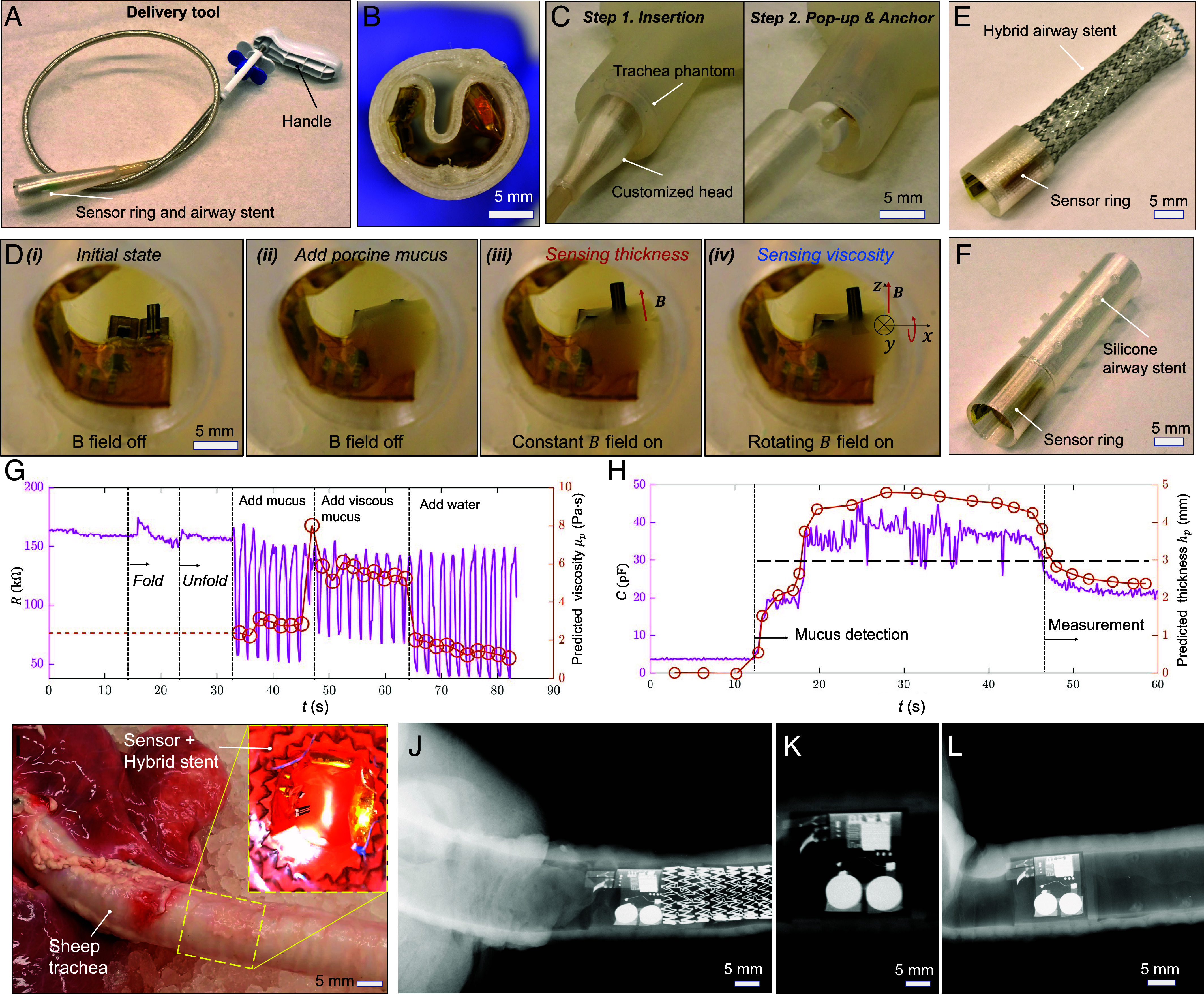
Demonstration of the deployment and sensing function of the sensory artificial cilia inside a trachea phantom and a sheep trachea ex vivo. (A) Optical image of the delivery tool with a customized head for constraining the sensory ring. (B) Optical image of the sensory ring inside the head of the delivery tool. (C) Movie S4 frames of the delivery tool with the sensory ring embedded in the deployment process. (D) Movie S3 frames of the device deployed inside a trachea phantom. (i) No mucus. (ii) Add mucus, no actuation. (iii) Sensing mucus thickness, magnetically actuated. (iv) Sensing mucus viscosity, magnetically actuated. (E) Image of the hybrid stent integrated with the sensory ring. (F) Silicone airway stent integrated with the sensory ring. (G) Real-time viscosity sensor signal when varying the mucus viscosity. (H) Real-time mucus layer thickness sensor signal when varying the mucus layer thickness. When mucus layer thickness passes the threshold, alarm will be triggered for further intervention. (I) Optical image of the sensory ring with a hybrid stent delivered inside a sheep trachea. (J–L) X-ray images of the sensory ring with a metal stent, only a sensory ring, and a sensory ring with a silicone stent inside a sheep trachea, respectively.
We further demonstrate the capability of integrating the sensory artificial cilia with airway stents for sensing mucus viscosity and layer thickness using a trachea phantom. Fig. 6 E and F show sensory rings integrated with a hybrid airway stent and a silicone airway stent, respectively. The hybrid airway stent with a sensory ring can be delivered using a customized flexible delivery tool by folding the hybrid stent and compressing the sensory ring. Meanwhile, the silicone airway stent with a sensory ring can be delivered into the trachea using a rigid bronchoscope.
To demonstrate the sensing ability in a trachea phantom, we plot the data of the sensed time-varying mucus viscosity and layer thickness using the sensor ring inside an airway phantom in Fig. 6 G and H, respectively. The two sensors will operate sequentially. First, the mucus layer thickness will be measured using the layer thickness sensor, which includes online calibration capabilities. If the measured thickness is sufficient to fully submerge the viscosity sensor, the viscosity sensor will then be activated by a rotating magnetic field. Fig. 6G illustrates the resistance change of the viscosity sensor during the deployment and viscosity measurement. Initially, the resistance fluctuates slightly due to vibration when the sensor is folded, but it quickly stabilizes as the sensory ring is deployed and expands. When mucus is added and a rotational magnetic field is applied, the sensor effectively responds to changes of viscosity over time promising for monitoring the viscosity changes due to inflammation or dehydration.
Moreover, Fig. 6H shows the capacitance change during mucus layer thickness measurement. The mucus accumulation is detected by an abrupt change in capacitance, which quickly rises to its maximum value while the sensor is lying down for the self-calibration process. After the sensor is lifted, the mucus gradually slips away from the sensor, allowing for the computation of mucus layer thickness based on the current mucus coverage and tilting angle. When the mucus layer thickness reaches a threshold, an alarm will be triggered so that further intervention could be carried out in time. To accurately determine the sensor’s bending angle within the body, the onboard magnetic sensor will measure the magnetic field and calculate the angle based on a preestablished mapping. This mapping correlates the magnetic sensor readings with the sensor’s angle, which can be calibrated as demonstrated in SI Appendix, Fig. S15. To measure mucus thickness when the sensor is inside the body, we will leverage the magnetically controlled bending angle of the layer thickness sensor. In the experiments, we will begin by measuring the maximum capacitance (Cmax) with the sensor positioned flat, fully submerged in the mucus. Then, a magnetic field will be applied to tilt the sensor, with the tilting angle determined by the detected magnetic field angle. The sensor’s tilting angle will be gradually increased until the capacitance reaches Cmax. This approach avoids sensor saturation while ensuring the reading is sufficiently large. If the sensor still registers maximum capacitance even at a 90° angle, it indicates that the mucus layer thickness exceeds the sensor’s length.
Additionally, we demonstrate the combination of the sensory ring with different types of airway stents and its resilience in a sheep trachea. Fig. 6I shows the delivery of a hybrid stent and a sensory ring into a sheep trachea ex vivo, demonstrating the resilience of the sensory ring during the delivery process. For clear visualization and illustration, the deployment processes of the sensor ring with a hybrid stent and a silicone stent in a transparent trachea phantom (SI Appendix, Fig. S16). The deployment process and result of a sensory ring with a hybrid stent, a sensory ring alone, and a sensory ring with a silicone stent inside a sheep trachea are further recorded and verified using an X-ray medical imaging machine as shown in Fig. 6 J–L. The results further demonstrate the feasibility of visualizing the sensory airway stent inside the animal organs.
Discussion
In summary, our research has culminated in the development of a novel airway stent equipped with integrated artificial cilia. These artificial cilia possess the remarkable ability to sense various mucus conditions, including viscosity, thickness, and temperature, thereby holding promise for monitoring stent patency. Our viscosity sensor operates on the principle of an artificial cilium actuated by an external magnetic field, while a flexible strain gauge sensor measures the curvature of the cilium. For mucus thickness sensing, we employ a capacitor that can be tilted by an external magnetic field for self-calibration and reconfigurable sensing range and sensitivity. Furthermore, temperature data are also captured using an onboard sensor. The artificial cilium sensors are activated by a customized wearable magnetic actuation system, facilitating real-time monitoring of lung physiology and mucus properties. By continuously gathering data on mucus viscosity, quantity, and other pertinent parameters, these sensors provide continuous monitoring of airway conditions and stent patency for timely interventions.
The variance among the sensors has been investigated. As shown in SI Appendix, Fig. S17, the thickness of the viscosity sensor is the primary factor influencing the sensor’s bending angle when actuated in the same fluids under identical magnetic fields. Despite these variations, all viscosity sensors can be calibrated after fabrication by actuating them in liquids with known viscosities. The layer thickness sensors do not require precalibration, even though their capacitance may vary with changes in mucus thickness, as demonstrated in SI Appendix, Fig. S18. These sensors are designed for online calibration using magnetic field actuation. After implantation, they can be calibrated and subsequently used to measure mucus thickness postcalibration.
Repeatability and durability are also crucial for both sensors. To assess these properties, we conduct cyclic actuation experiments. First, we actuated a viscosity sensor in a liquid for N = 3,000 cycles while monitoring its electrical resistance. As shown in SI Appendix, Fig. S19A, the peak-to-peak value of the electrical resistance signal remains relatively constant, with zoomed-in plots in SI Appendix, Fig. S19B further illustrating this stability. We also actuate a layer thickness sensor in mucus, controlling its bending angle between zero and 90° for N = 3,000 cycles while simultaneously measuring the sensor’s capacitance. As shown in SI Appendix, Fig. S20, the minimum and maximum capacitances remain relatively stable, demonstrating the sensor’s repeatability. Additionally, the online calibration mechanism allows for compensation of any sensor degradation through recalibration.
To pave the way for future in vivo trials, several critical considerations must be addressed. First, optimizing the electronic device’s battery life is crucial which can be achieved by fine-tuning the sensor update frequency. For example, adjusting the update interval to every 30 min for a 10-s measurement could extend the device’s operational lifespan to 10 d (SI Appendix, Fig. S21). To further extend the lifetime, we will integrate wireless charging unit (15, 18, 23) for remote powering of the stent. Moreover, ensuring biocompatibility is crucial, and this can be achieved by encapsulating the electronic board with polyimide (PI) tapes on both surfaces and coating the magnetic sensor with PDMS. To further enhance biocompatibility, the viscosity sensor should be coated, with magnetic particles potentially coated in SiO2 (34). Additionally, the device’s biocompatibility could be further improved by applying a parylene-C coating. Verification of biocompatibility will require in vitro testing using cell viability analysis. Last, the anchoring force of the sensor ring in an animal trachea needs to be quantified when bonding with a hybrid stent. To further quantify stent migration and other complications when implanted in an animal model, the in vivo performance of artificial cilia will be assessed using Computational Tomography.
In the future, multimodal sensors (35) capable of detecting temperature, pressure, hydration, stent migration, and air flow will be integrated to enable comprehensive monitoring of mucus properties and airway conditions. This continuous monitoring would allow for the early detection of changes in mucus properties or the onset of complications (11, 36), facilitating timely interventions (37) and personalized close-loop therapy (38). By closely tracking mucus properties and airway health, our device can support tailored treatment strategies for each patient’s unique needs, optimizing therapeutic outcomes and preventing disease exacerbations.
Materials and Methods
Fabrication of Sensory Artificial Cilia for Viscosity Sensing.
The fabrication process for the sensory artificial cilia commences with the preparation of LIG. Initially, a layer of polyethylene terephthalate (PET) was affixed to a glass slide, followed by the spin-coating of Polyvinyl alcohol (PVA) onto the PET layer to establish an adhesive surface. After curing the PVA at 100 °C for 5 min, a layer of PI tape was applied onto the PVA layer. Subsequently, a CO2 laser was employed to induce graphene formation from the PI tape, utilizing parameters set to 20% power, 50% speed, and 1,000 pixels per inch (PPI). Once the graphene was induced from the PI, a magnetic composite comprising NdFeB particles (MQP-15-7, Magnequench; average diameter: 5 μm) and PDMS at a weight ratio of 2:1 was spin-coated onto the graphene layer at 2,700 revolution per minute (RPM) for 1 min. The coated material was then cured on a hot plate at 100 °C for 10 min. The resulting LIG-polymer layer, along with the PI layer, was carefully removed from the glass slide. A heating process was applied to facilitate the separation of the LIG-polymer from the PI layer. Subsequently, the transferred LIG was patterned into the desired sensory artificial cilium shape using a Ultraviolet (UV) laser machine (LPKF U4, from LPKF Laser &Electronics North America). This artificial cilium was affixed to a backing layer using Ecoflex 00-30. Connection between the LIG on the artificial cilium and conductive traces was established using carbon or silver paste. A thin layer of PDMS or Ecoflex 00-30 was then applied to the LIG to serve as an encapsulation layer. Additionally, the traces were encapsulated using Ecoflex 00-30 for added protection. Finally, the sensory artificial cilium was magnetized, allowing the integration into the sensor ring.
Fabrication of Sensory Artificial Cilia for Mucus Layer Thickness Sensing.
Initially, a layer of magnetic composite substrate composed of Ecoflex 00-30 and NdFeB (with a weight ratio of 1:2) was prepared. Following this, a PI film was applied to enhance sensor rigidity and electrode adhesion. The electrodes, fabricated from silver pastes, were cured on a hot plate at 150 °C for 20 min. Subsequently, electrode patterning for capacitors was executed using the LPKF U4 laser machine. To prevent shorting of the capacitor to surrounding fluids, a layer of PDMS was spin-coated onto the electrodes at 4,000 RPM for 1 min, then cured at 100 °C for 10 min. Ecoflex 00-30 might be used as an alternative coating material for more viscous liquid as the adhesion between the coating and mucus is smaller compared with PDMS. Next, LIG patches were affixed to the electrodes and electrical traces using silver paste, serving as flexible conductive hinges. The sensor assembly was then magnetized at 2.2 Tesla. For insulation, the LIG patches and silver pastes were encapsulated within Ecoflex 00-30. This encapsulation process ensures electrical integrity and environmental resilience for the sensor system.
Fabrication of the Electronic Circuit for Computation and Communication.
Custom circuits were designed to accommodate an MDBT42V-P512KV2 board (Raytac Corporation) (SI Appendix, Table S1) and a three-axis Hall-effect sensor (TLV493D-A1B6, Infineon Technologies, AG). These circuit boards were designed using Electronic Design Automation (EDA) software, specifically EasyEDA, as illustrated in SI Appendix, Fig. S22. Subsequently, the Printed Circuit Boards (PCBs) were fabricated using the LPKF U4 laser machine. During the PCB assembly phase, a paste mask stencil was employed to accurately apply solder paste onto the copper pads, ensuring proper connection to the nRF52832 microprocessor inside the MDBT42V-P512KV2 board. Following this, other essential components such as capacitors were meticulously soldered onto the custom circuits. For a comprehensive listing of these components, refer to SI Appendix, Table S1. Programming of the BLE SoC was accomplished using the nRF52 Development Kit from Nordic Semiconductor (39). The program was initially compiled in Arduino IDE 1.8.19, utilizing the Adafruit Bluefruit library, before being uploaded to the BLE SoC via the nRF52 Development Kit. To provide power supply, a battery board equipped with two alkaline batteries (LR626, 1.5 V, 18 mAh) was affixed to the custom boards, ensuring seamless functionality. The sampling rate and resolution data of the sensory board are listed in SI Appendix, Table S2.
The Customized Delivery Tool.
The customized flexible delivery tool was prepared by adapting a commercial stent delivery tool designed for self-expandable stents. A conical outer shell, boasting a maximum inner diameter of 16 mm and a length of 25 mm, was 3D printed using TPU and securely affixed to the tip of the stent delivery tool. During the deployment process, the sensory ring was securely bonded to a metal stent and adeptly folded to conform to the dimensions of the cone-shaped structure. Simultaneously, the metal stent was meticulously folded within the existing plastic shell of the delivery tool, ensuring a compact and streamlined configuration. Upon reaching the targeted location within the trachea, the sensor ring was released, popping up together with the metal stent. This seamless integration ensured precise positioning and optimal functionality of the sensory ring within the trachea, facilitating accurate monitoring and data collection.
Experimental Setup for Testing the Sensors.
In a bench test, the viscosity sensor was interfaced with copper wires to enable resistance measurement. Subsequently, it was positioned within a transparent container, suspended approximately 3 cm above two rotating permanent magnets. These magnets were measured with dimensions of 25 mm by 25 mm by 25 mm (N45, from SuperMagnetMan). Once the sensor was submerged in the liquid of interest, viscosity measurements were conducted using Arduino Uno and LabVIEW 2020 (National Instruments). This setup also allowed for precise and reliable assessment of liquid layer thickness, facilitating comprehensive analysis of the fluid’s properties.
Wearable Magnetic Actuation System.
The system comprises housing, rails, a ground plate, slider crank mechanism, translation table, shaft stabilizer, motor mount, and sleeves for the magnetic actuation module. The system housing was fabricated by 3D printing polylactic acid (PLA). Additionally, the top plate and driver component board were precision-cut from 3-mm thick plywood using a laser machine (VLS3.60DT, Universal Laser Systems). For the magnetic actuation unit, two cylinderical NdFeB magnets with radial magnetization (diameter: 25 mm, length: 25 mm, N45 grade, from Applied Magnets) were housed within PLA sleeves, designed to prevent magnet rotation. These sleeves were carefully aligned and joined together using a vice, ensuring correct orientation, and then fused together through plastic welding. The rotation of the permanent magnets was achieved using an encoder gear motor (N20) controlled by a DC motor driver (L298N). Meanwhile, a servo motor (MG996R) was employed to regulate the position of the permanent magnets through a sliding-crank linkage mechanism. To manage the operation of both the DC motor and servo motor, a wirelessly controlled embedded controller (Arduino Nano 33 BLE Sense) was utilized. Power was supplied by two rechargeable batteries (3.7 V, 5,000 mAh, Model: 18650, from Tokeyla) for the motors, with an additional 9 V battery dedicated to powering the embedded controller. The magnetic field at the sensor location was controlled by rotating and translating the magnet inside the wearable magnetic actuation system.
Preparing Viscous Liquids.
Different viscous liquids were prepared by mixing syrup (Karo Light corn syrup, dynamic viscosity μ = 7.8 Pa·s) with different amount of water. For example, the syrup-water mixture of a weight ratio of 100:1 has the viscosity of μ = 2.8 Pa·s. Their viscosities were measured by a viscometer (NDJ–8S, Bonvoisin). The mucus was prepared by mixing porcine mucin (Chem-impex International Inc.) with water according to different weight ratios. The mixtures were then stirred for 1 h at room temperature (23 °C).
Fitting Function of the Viscosity Sensor.
The fitting function used during the calibration in Matlab was “Loess- Quadratic,” also known as locally weighted polynomial regression. The parameters used in the fitting functions are shown in SI Appendix, Fig. S23, with a span of 20% of the dataset and quadratic polynomial implemented. All data were equally weighted.
Data Collection on the BLE SoC and in Matlab.
Arduino code specifically tailored for the Adafruit Bluefruit nRF52 Board was employed to program the nRF52832 chip. Additionally, a dedicated Arduino library for the 3D magnetic sensor (TLV493D-A1B6) from Infineon Technologies Inc. was utilized to activate the onboard magnetic sensor, ensuring accurate and reliable data collection. To streamline data acquisition and processing, the Bluetooth Toolbox in Matlab 2022a (Mathworks Inc.) was used, which provided the functions for BLE communication, enabling seamless integration with the nRF52 chip.
Supplementary Material
Appendix 01 (PDF)
Mucus viscosity sensing mechanism. This video first shows the mucus viscosity sensing mechanism in liquids of different viscosities and at different actuation frequencies. It then shows the process of monitoring mucus viscosity.
Mucus layer thickness sensing mechanism. This video first shows the mucus layer thickness sensing mechanism and the calibration process. It also shows the reconfigurability of the sensor by external magnetic fields.
Sensory airway stent inside a phantom with battery and BLE SoC and the wearable magnetic actuation system. This video first shows the sensor signals inside a trachea phantom with monitored mucus viscosity, layer thickness, and temperature. It then shows the magnetic wearable actuation system and wireless data monitoring.
Deployment process of the sensor ring and airway stents. This video first shows the deployment of only the sensor ring inside a phantom. It then shows deploying the sensory ring and the hybrid stent inside a trachea phantom and a sheep trachea ex vivo.
Acknowledgments
We would like to thank the funding support from the Vanderbilt University School of Engineering and Vanderbilt Institute for Surgery and Engineering. We also acknowledge Vanderbilt Institute for Nanoscale Science and Engineering and Oak Ridge National Laboratory for facility support.
Author contributions
X.D. designed research; Y.W., C.N., A.K., S.E., H.V., J.Q., N.P., and V.S. performed research; Y.W. and C.N. analyzed data; F.M., C.D., and C.O. edited the paper; and X.D. and Y.W. wrote the paper.
Competing interests
X.D. and Y.W. have a pending provisional patent.
Footnotes
This article is a PNAS Direct Submission.
Data, Materials, and Software Availability
The codes used in this study are available at https://github.com/dong-mrlab/sensory_stent. All other data are included in the article and/or supporting information.
Supporting Information
References
- 1.Folch E., Keyes C., Airway stents. Ann. Cardiothorac. Surg. 7, 27383–27283 (2018). [DOI] [PMC free article] [PubMed] [Google Scholar]
- 2.Guibert N., Saka H., Dutau H., Airway stenting: Technological advancements and its role in interventional pulmonology. Respirology 25, 953–962 (2020). [DOI] [PubMed] [Google Scholar]
- 3.Ernst A., Feller-Kopman D., Becker H. D., Mehta A. C., Central airway obstruction. Am. J. Respir Crit. Care Med. 169, 1278–1297 (2004). [DOI] [PubMed] [Google Scholar]
- 4.Herlitz G. N., Sternberg D. I., Palazzo R., Arcasoy S., Sonett J. R., Treatment of bronchomalacia in cystic fibrosis by silicone stent. Ann. Thorac. Surg. 82, 2268–2270 (2006). [DOI] [PubMed] [Google Scholar]
- 5.Bustamante-Marin X. M., Ostrowski L. E., Cilia and mucociliary clearance. Cold Spring Harb. Perspect. Biol. 9, a028241 (2017). [DOI] [PMC free article] [PubMed] [Google Scholar]
- 6.Fahy J. V., Dickey B. F., Airway mucus function and dysfunction. N. Engl. J. Med. 363, 2233–2247 (2010). [DOI] [PMC free article] [PubMed] [Google Scholar]
- 7.Evans C. M., Koo J. S., Airway mucus: The good, the bad, the sticky. Pharmacol. Ther. 121, 332–348 (2009). [DOI] [PMC free article] [PubMed] [Google Scholar]
- 8.Lai S. K., Wang Y. Y., Wirtz D., Hanes J., Micro- and macrorheology of mucus. Adv. Drug Deliv. Rev. 61, 86–100 (2009). [DOI] [PMC free article] [PubMed] [Google Scholar]
- 9.Xiao B., Xu Y., Edwards S., Balakumar L., Dong X., Sensing mucus physiological property in situ by wireless millimeter-scale soft robots. Adv. Funct. Mater. 34, 2307751 (2024). [Google Scholar]
- 10.de Jong P. A., Müller N. L., Paré P. D., Coxson H. O., Computed tomographic imaging of the airways: Relationship to structure and function. Eur. Respir. J. 26, 140–152 (2005). [DOI] [PubMed] [Google Scholar]
- 11.Lee H. J., et al. , Airway stent complications: The role of follow-up bronchoscopy as a surveillance method. J. Thorac. Dis. 9, 4651–4659 (2017). [DOI] [PMC free article] [PubMed] [Google Scholar]
- 12.Crutu A., Baldeyrou P., “Stent monitoring and care” in Normal and Pathological Bronchial Semiology, Baldeyrou P., Hanna A., Crutu A., Eds. (Elsevier, 2019), pp. 163–174. [Google Scholar]
- 13.Costanzo I., Sen D., Rhein L., Guler U., Respiratory monitoring: Current state of the art and future roads. IEEE Rev. Biomed. Eng. 15, 103–121 (2022). [DOI] [PubMed] [Google Scholar]
- 14.Vishnu J., Manivasagam G., Perspectives on smart stents with sensors: From conventional permanent to novel bioabsorbable smart stent technologies. Med. Dev. Sens. 3, e10116 (2020). [Google Scholar]
- 15.Zhang C., et al. , Wirelessly powered deformable electronic stent for noninvasive electrical stimulation of lower esophageal sphincter. Sci. Adv. 9, eade8622 (2023). [DOI] [PMC free article] [PubMed] [Google Scholar]
- 16.Atanasova K. R., Reznikov L. R., Strategies for measuring airway mucus and mucins. Respir. Res. 20, 261 (2019). [DOI] [PMC free article] [PubMed] [Google Scholar]
- 17.Liu M., et al. , Non-invasive flexible electro-mechanical sensors for human respiratory monitoring and chronic disease management. Adv. Mater. Technol. 9, 2302010 (2024). [Google Scholar]
- 18.Yoo J. Y., et al. , Wireless broadband acousto-mechanical sensing system for continuous physiological monitoring. Nat. Med. 29, 3137–3148 (2023). [DOI] [PubMed] [Google Scholar]
- 19.Che Z., et al. , Speaking without vocal folds using a machine-learning-assisted wearable sensing-actuation system. Nat. Commun. 15, 1–11 (2024). [DOI] [PMC free article] [PubMed] [Google Scholar]
- 20.Jiang T., et al. , Wearable breath monitoring via a hot-film/calorimetric airflow sensing system. Biosens. Bioelectron. 163, 112288 (2020). [DOI] [PubMed] [Google Scholar]
- 21.Jeong H., et al. , Closed-loop network of skin-interfaced wireless devices for quantifying vocal fatigue and providing user feedback. Proc. Natl. Acad. Sci. U.S.A. 120, e2219394120 (2023). [DOI] [PMC free article] [PubMed] [Google Scholar]
- 22.Veletić M., et al. , Implants with sensing capabilities. Chem. Rev. 122, 16329–16363 (2022). [DOI] [PubMed] [Google Scholar]
- 23.Kwon K., et al. , A battery-less wireless implant for the continuous monitoring of vascular pressure, flow rate and temperature. Nat. Biomed. Eng. 7, 1215–1228 (2023). [DOI] [PubMed] [Google Scholar]
- 24.Lin M., Hu H., Zhou S., Xu S., Soft wearable devices for deep-tissue sensing. Nat. Rev. Mater. 7, 850–869 (2022). [Google Scholar]
- 25.Ruiz L. J. L., Zhu J., Fitzgerald L., Quinn D., Lach J., “Capacitive sensing for monitoring stent patency in the Central Airway” in 2021 43rd Annual International Conference of the IEEE Engineering in Medicine and Biology Society (EMBC), (IEEE, 2021), pp. 5441–5445. [DOI] [PubMed] [Google Scholar]
- 26.Ciaffoni L., et al. , In-airway molecular flow sensing: A new technology for continuous, noninvasive monitoring of oxygen consumption in critical care. Sci. Adv. 2, e1600560 (2016). [DOI] [PMC free article] [PubMed] [Google Scholar]
- 27.ul Islam T., et al. , Microscopic artificial cilia - a review. Lab. Chip. 22, 1650–1679 (2022). [DOI] [PMC free article] [PubMed] [Google Scholar]
- 28.Gu H., et al. , Magnetic cilia carpets with programmable metachronal waves. Nat. Commun. 11, 2637 (2020). [DOI] [PMC free article] [PubMed] [Google Scholar]
- 29.Wang W., et al. , Cilia metasurfaces for electronically programmable microfluidic manipulation. Nature 605, 681–686 (2022). [DOI] [PubMed] [Google Scholar]
- 30.Dong X., et al. , Bioinspired cilia arrays with programmable nonreciprocal motion and metachronal coordination. Sci. Adv. 6, eabc9323 (2020). [DOI] [PMC free article] [PubMed] [Google Scholar]
- 31.Han J., et al. , Actuation-enhanced multifunctional sensing and information recognition by magnetic artificial cilia arrays. Proc. Natl. Acad. Sci. U.S.A. 120, e2308301120 (2023). [DOI] [PMC free article] [PubMed] [Google Scholar]
- 32.Prasher P., et al. , Targeting mucus barrier in respiratory diseases by chemically modified advanced delivery systems. Chem. Biol. Interact. 365, 110048 (2022). [DOI] [PubMed] [Google Scholar]
- 33.Chen L., Bonaccurso E., Effects of surface wettability and liquid viscosity on the dynamic wetting of individual drops. Phys. Rev. E Stat. Nonlin. Soft Matter. Phys. 90, 022401 (2014). [DOI] [PubMed] [Google Scholar]
- 34.Kim Y., Parada G. A., Liu S., Zhao X., Ferromagnetic soft continuum robots. Sci. Robot 4, 7329 (2019). [DOI] [PubMed] [Google Scholar]
- 35.Ni X., et al. , Automated, multiparametric monitoring of respiratory biomarkers and vital signs in clinical and home settings for COVID-19 patients. Proc. Natl. Acad. Sci. U.S.A. 118, e2026610118 (2021). [DOI] [PMC free article] [PubMed] [Google Scholar]
- 36.Murase K., Neri S., Tachikawa R., Tomii K., Tracheal stent placement via a tracheostomy for tracheal stenosis after inhalation injury. Burns 36, e132–e135 (2010). [DOI] [PubMed] [Google Scholar]
- 37.Bayfield K. J., et al. , Time to get serious about the detection and monitoring of early lung disease in cystic fibrosis. Thorax 76, 1255–1265 (2021). [DOI] [PubMed] [Google Scholar]
- 38.Wang Y., Sharma S., Maldonado F., Dong X., Wirelessly actuated ciliary airway stent for excessive mucus transportation. Adv. Mater. Technol. 8, 2301003 (2023). [Google Scholar]
- 39.Wang Y., Edwards S., Vu H., Quatela J., Dong X., sensory_stent. Github. https://github.com/dong-mrlab/sensory_stent. Deposited 12 September 2024.
Associated Data
This section collects any data citations, data availability statements, or supplementary materials included in this article.
Supplementary Materials
Appendix 01 (PDF)
Mucus viscosity sensing mechanism. This video first shows the mucus viscosity sensing mechanism in liquids of different viscosities and at different actuation frequencies. It then shows the process of monitoring mucus viscosity.
Mucus layer thickness sensing mechanism. This video first shows the mucus layer thickness sensing mechanism and the calibration process. It also shows the reconfigurability of the sensor by external magnetic fields.
Sensory airway stent inside a phantom with battery and BLE SoC and the wearable magnetic actuation system. This video first shows the sensor signals inside a trachea phantom with monitored mucus viscosity, layer thickness, and temperature. It then shows the magnetic wearable actuation system and wireless data monitoring.
Deployment process of the sensor ring and airway stents. This video first shows the deployment of only the sensor ring inside a phantom. It then shows deploying the sensory ring and the hybrid stent inside a trachea phantom and a sheep trachea ex vivo.
Data Availability Statement
The codes used in this study are available at https://github.com/dong-mrlab/sensory_stent. All other data are included in the article and/or supporting information.