

ABSTRACT
Objective
Currently, there is no research that includes a comprehensive three‐dimensional fracture mapping encompassing all types of Pilon fractures. Moreover, the existing classification systems for Pilon fractures exhibit only moderate to fair consistency and reproducibility. Additionally, some of these classification systems fail to accurately depict the morphological characteristics of the fractures. This study aimed to create a fracture map encompassing all types of Pilon fractures by three‐dimensional fracture mapping. In addition, this study conducted a finite element analysis of the normal ankle joint, and based on the distribution of fracture lines and the stress distribution at the distal tibia, proposed a new classification for Pilon fractures.
Methods
A retrospective analysis of Pilon fractures in our hospital from January 2018 to January 2024 was performed. A total of two hundred forty‐four Pilon fractures were included, and their fracture lines were transcribed onto the tibia and fibula templates, and fracture maps and heat maps were created. A nonhomogeneous model of the ankle joint was constructed and verified, and the stress distribution on the distal tibia articular surface was measured and analyzed in three models (neutral, dorsiflexed, and plantarflexed model). Based on the fracture map and stress distribution, a five‐column classification system for Pilon fractures was proposed, and the intraobserver and interobserver reliability was calculated using Cohen and Fleiss k statistics.
Result
The fracture line on the distal tibia articular surface showed a V‐shaped distribution. One branch extended from the junction of the medial malleolar articular surface and the inferior tibial articular surface toward the medial malleolus. The other branch extended from the middle of the fibular notch to the posterior part of the medial ankle, toward the tibial shaft. The fibula fracture line mainly extended from the anterior and lower part of the lateral malleolus to the posterior and upper part. As evidenced by the neutral, dorsiflexed, and plantar flexion models, the stress on the posterolateral articular surface (posterolateral column) was low, while the majority of the stress was concentrated in the center. Three‐column fractures were the most common, followed by two‐column fractures. Using the five‐column classification, the K‐weighted values of interobserver and intraobserver analysis were 0.653 (p < 0.001) and 0.708 (p < 0.001), respectively.
Conclusions
In this study, the fracture line and morphological characteristics of Pilon fractures were analyzed in detail by three‐dimensional mapping. In addition, this study conducted a finite element analysis of the stress distribution on the distal tibial joint surface of the normal ankle joint. Moreover, a novel classification system was proposed to reflect these findings. The new classification not only exhibits greater consistency, facilitating accurate communication of fracture characteristics among surgeons, but also aids in understanding the mechanisms of injury and formulating surgical strategies.
Keywords: classification, computed tomography, finite element analysis, fracture mapping, pilon fractures
In this study, the morphological characteristics of Pilon fractures were clarified in detail by 3D mapping. This provides a basis for the diagnosis, classification, selection of treatment methods, internal fixation design, and statistical analysis of fracture lines of Pilon fractures.

1. Introduction
Pilon fractures are common injuries, accounting for about 5%–7% of all tibial fractures [1, 2, 3, 4]. The Pilon fracture is a fracture of the distal tibial articular surface that extends to the metaphysis of the tibia caused by vertical force [4, 5, 6]. This injury is mostly caused by high‐energy trauma, such as a high fall or a vehicle accident [7]. However, surgical treatment is challenging due to the poor soft tissue coverage around the ankle and the complexity of this injury. A better understanding of the morphological characteristics and a reasonable classification of fractures will assist surgeons in developing treatment strategies and improving successful outcomes [8, 9].
Fracture mapping is a method that involves the three‐dimensional (3D) reconstruction of multiple fracture models, overlaying their fracture lines onto a single normal model, thereby providing a visual representation of the morphology of this type of fracture. Understanding the morphological characteristics of fractures contributes to the development of fracture classification systems, the design of implants, surgical strategies, and the statistics of fracture lines. Current research on fracture mapping of Pilon fractures is limited to specific fracture types (such as posterior Pilon fractures or OTA/AO Type 43C3 ankle fractures) and predominantly employs two‐dimensional (2D) fracture mapping techniques [9, 10, 11]. The 2D fracture mapping can only depict the fracture morphology from specific perspectives. In the current study, not only did they not reduce the fracture fragments, but they also directly replaced the fracture line trajectory with a straight line, which appears to pose significant challenges in accurately reconstructing the true morphology of Pilon fractures [11]. Compared to 2D fracture mapping, 3D fracture mapping provides greater accuracy, intuition, and comprehension. To the best of our knowledge, this study is the first to perform 3D fracture mapping of all types of Pilon fractures.
The ideal classification system for pilon fractures should be easy to apply, comprehensive, possess sufficient reliability and reproducibility, and effectively communicate the morphological characteristics of the fractures among clinicians. Currently, the commonly used classification systems for pilon fractures are the AO/OTA classification and the Ruedi–Allgower classification. However, previous studies have indicated certain limitations: both classifications demonstrate general to moderate consistency and reproducibility, which hinders their widespread adoption. Furthermore, the Ruedi–Allgower classification simplistically categorizes pilon fractures into three types without providing accurate information regarding the fracture morphology [8, 12, 13, 14]. The current classification systems for Pilon fractures, including Ruedi–Allgower and AO/OTA, do not include all types of Pilon fractures and have limited efficacy in guiding therapeutic strategies and surgical approaches.
The primary objectives of this study were as follows: (1) Define and analyze the fracture lines and morphological features of all types of Pilon fractures by 3D mapping. (2) Conduct finite element analysis of normal ankle joints to gain a better understanding of stress distribution. (3) Establish a new classification based on heat map and stress distribution, guiding surgical strategies, preoperative planning, and communication among surgeons, and evaluate its reliability and repeatability.
2. Methods
2.1. Subjects
This study was approved by the Medical Ethics Committee of the Second Hospital of Jilin University (approval number: 2024020). With this approval, the study has been exempted from obtaining informed consent. A retrospective analysis of Pilon fractures that occurred in our hospital from January 2018 to January 2024 was carried out. Inclusion criteria are as follows: (1) Pilon fractures characterized by: (a) fracture lines involving the distal joint surface of the tibia, (b) fracture lines extending proximally above the metaphysis, and (c) collapse of the distal joint surface of the tibia [15]; (2) complete demographic data; (3) age 18 years and older; (4) closed fractures; and (5) preoperative ankle computed tomography (CT) scans conducted at our institution, with reliable imaging data sufficient for 3D modeling. Exclusion criteria are as follows: (1) Isolated medial malleolus fractures; (2) isolated posterior malleolus fractures; (3) pathological fractures (excluding osteoporosis); (4) open fractures; (5) poor quality CT scan data (slice thickness > 3 mm, incomplete scanning images); and (6) history of ankle surgery, rheumatic diseases, congenital or acquired ankle deformities, or primary ankle osteoarthritis.
2.2. Fracture Mapping
The left tibia and fibula of a healthy adult male (27 years old with no history of ankle injury) were subjected to 3D reconstruction and were used as the standard model in this study. The mapping process is shown in Figure 1. The CT data were exported in Digital Imaging and Communication in Medicine (DICOM) format. Subsequently, the Mimics software (Materialise, Leuven, Belgium) was used to model and separate the fracture fragments. Then, the reconstructed models were exported to 3‐matic 13.0 (Materialise, Leuven, Belgium) for movement, rotation, and size standardization to match the standard model. All right‐sided Pilon fractures were mirrored to the left side. The transparency of the appropriate standard model was adjusted, and the normalized fracture model was superimposed on the standard model. After aligning the anatomical markers, the curve tools in 3‐matic were employed to draw the fracture line. Finally, the heat maps of the fracture were generated in E‐3D (Central South University, Changsha, China).
FIGURE 1.

Representative images of steps in the method used for 3D mapping of Pilon fractures. In this example of a Pilon fracture, each fragment was reconstructed (A), segmented (B), and virtually reduced (C). The fracture was then mirrored (if left) and matched to the model (C) of one‐third of the tibia. The contour of every fracture fragment was marked with smooth curves to delineate the fracture lines (D).
2.3. Finite Element Analysis
In this study, three models of the ankle joint were constructed: the dorsiflexion, plantarflexion, and vertical positions. An informed consent statement was signed after receiving the oral and written description of the experiment prior to the start of experiment. And ethical approval was obtained from the Medical Ethics Committee of the Second Hospital of Jilin University (approval number: 202421). This research will strictly protect the privacy of volunteers. According to previous research, this study exclusively reconstructs the bone and ligament structures influencing the distal tibial joint surface [16, 17, 18, 19]. The impact of the tarsal bones, metatarsals, phalanges, and their associated ligaments on the distal tibial joint surface is minimal; therefore, they were not included in the reconstruction. Figure 2 displays an overview of the finite element analysis workflow. The images in DICOM format were imported into Mimics 21.0 (Materialise, Leuven, Belgium) to reconstruct the 3D model of the ankle. The STL model was then imported into the Geomagic Studio 2013 (3D Systems, Rock Hill, SC, USA) for further processing to achieve a more accurate model. Subsequently, the model was assembled in SolidWorks 2017 (Dassault Systemes, MA, USA), and ligaments and cartilage were reconstructed.
FIGURE 2.

Overview of finite element analysis workflow. (A) First, acquire the three‐dimensional CT data of the volunteers; (B) reconstruct the bone using Mimics; (C) further refine the model in Geomagic; (D) perform ligament reconstruction in SolidWorks; (E) mesh the model in Hypermesh; (F) import the mesh model into Mimics for material assignment; (G) import the model into Ansys for solving; and (H) conduct post‐processing of the results in Workbench.
All models were imported into Hypermesh 2020 (Altair Engineering, Troy, MI, USA) and divided into triangular meshes with the element type C3D4. The element sizes were set to 1 mm. A mesh size convergence test was carried out to ensure the accuracy of the results.
The Mimics software was used to define the ankle model with nonuniform material properties based on the gray values of the CT data. Previous studies reported that the material properties of bone are distributed according to the following formula [20]:
| (1) |
| (2) |
where ρ represents bone density, GV represents the gray value of bone in CT data, and E represents the elastic modulus (Figure 3). The Poisson's ratio (ν) for the tibia was set to 0.3 [21]. The properties of the ligaments are presented in Table 1.
FIGURE 3.

Material assignment for tibia and fibula. (A) Bone density (ρ) and elastic modulus (E) of each material. (B) Number of elements of every material. (C) External material properties of the tibia. (D) Internal material properties of the tibia.
TABLE 1.
Material properties of ligaments.
| Ligaments represented in models | Young's modulus (E), MPa | Poison's ratio (v) |
|---|---|---|
| Anterior tibiofibular (ATiFL) | 160 | 0.49 |
| Posterior tibiofibular (PTiFL) | 160 | 0.49 |
| Calcaneofibular (CaFL) | 512 | 0.49 |
| Tibiocalcaneal (TiCa) | 512 | 0.49 |
| Anterior talofibular (ATaFL) | 255.5 | 0.49 |
| Posterior talofibular (PTaFL) | 216.5 | 0.49 |
| Anterior tibiotalar (ATiTL) | 184.5 | 0.49 |
| Posterior tibiotalar (PTiTL) | 99.5 | 0.49 |
| Interosseous talocalcaneal (ITaCL) | 260 | 0.4 |
| Lateral talocalcaneal (LTaCL) | 260 | 0.4 |
| Medial talocalcaneal (MTaCL) | 260 | 0.4 |
| Posterior talocalcaneal (PTaCL) | 260 | 0.4 |
| Cartilage | 150 | 0.42 |
In this study, the main contact relationships were set to “bonded.” Vertical compressive loads of 500 and 100 N were applied to the upper part of the tibia and fibula of the model, respectively [19]. Three directional fixed constraints with complete degrees of freedom were set in the XYZ direction of the lower surface of the calcaneus. The Ansys Workbench 17 (ANSYS. Inc. Pittsburgh, USA) was used for solution and post‐processing of results. Von‐Mises stress was measured on the distal tibial articular surface. This model was validated by analyzing the maximum contact stress on the distal tibial articular surface.
2.4. Evaluation and Classification of Fracture
A five‐column classification of Pilon fractures (Figure 4A) was proposed based on fracture morphology and stress distribution. The fracture morphology of all patients was evaluated and classified by three observers using the five‐column classification. The three observers included a senior surgeon with over 15 years of experience in orthopedic trauma surgery and two others with over 5 years of experience in the same field.
FIGURE 4.

Five‐column classification of Pilon fracture and definition of posterolateral column. (A) Schematic layout of five‐column classification of Pilon fractures. (B) The definition of posterolateral column (L1:L2 = 6:1).
2.5. Statistical Analysis
Cohen or Fleiss k statistics were used to calculate the intraobserver and interobserver reliabilities, including 95% confidence intervals; Landis and Koch criteria were used to evaluate the level of agreement (0.00–0.20 indicated slight agreement, 0.21–0.40 fair, 0.41–0.60 moderate, 0.61–0.80 substantial, and 0.81–1.00 almost perfect) [22]. Data analysis was performed using SPSS 20.0 (SPSS Inc. Chicago, IL, USA).
3. Results
3.1. Characteristics of Patients
This study included a total of 244 patients, with 130 males and 114 females. The average age was 46.67 years old (18–78 years old). A total of 115 cases were left‐sided, and 129 cases were right‐sided. The demographic characteristics data are shown in Table 2.
TABLE 2.
Patient demographic characteristics.
| Characteristics | ||
|---|---|---|
| Patients (n = 244) | Sex ratio (male/female) | 130/114 |
| Age (±SD, years) | 46.67 ± 14.68 | |
| Age (±SD, years; male/female) | 43.8 ± 14.23/49.9 ± 14.68 | |
| Ankle | Left | 115 (47.1%) |
| Right | 129 (52.9%) |
3.2. Fracture Mapping
The fracture map and heat map are shown in Figure 5. The fracture line on the distal tibia articular surface showed a V‐shaped distribution. One branch extended from the junction of the medial malleolar articular surface and the inferior tibial articular surface toward the medial malleolus. The other branch extended from the middle of the fibular notch to the posterior part of the medial ankle, toward the tibial shaft. The fibula fracture line mainly extended from the anterior and lower part of the lateral malleolus to the posterior and upper part.
FIGURE 5.

The maps of the hot zones of 3D fracture lines of all Pilon fractures. (A–E) Representative views of the distal tibia and fibula. (F–J) 3D heat mapping superimposed with all Pilon fracture lines, including the axial, front, lateral, posterior, and medial views. Red represents a higher frequency of fracture line density.
3.3. Finite Element Analysis
In the validity verification experiment, the maximum contact stress of the distal tibial articular surface was 3.40–3.83 MPa, which was close to the existing experiment on the ankle, showing a similar stress distribution [19]. The model was validated as effective. The element size of the ankle was set at four different sizes for comparative analysis (Table 3) [23]. The peak equivalent stress value predicted by the reference example was compared, and the difference between the stress value of case A and the accuracy of the reference example was less than 5%. Therefore, the 1 mm mesh size was selected in this study. The stress distribution of the distal tibial articular surface in the three working conditions is shown in Figure 6. The finite element analysis revealed that the stress on the posterior‐lateral articular surface (posterolateral column) of the ankle joint was minimal in the neutral, dorsiflexed, and plantarflexed models, whereas the majority of stress was concentrated at its center.
TABLE 3.
Mesh convergence test of the mesh density of the FE model.
| Case | Element size (mm) | Number of elements | Percentage change in peak von mises stress |
|---|---|---|---|
| Reference case | 0.75 | 14,24,517 | — |
| Case A | 1 | 8,40,843 | < 5% |
| Case B | 1.25 | 6,17,491 | > 5% |
| Case C | 1.5 | 4,81,200 | > 5% |
FIGURE 6.
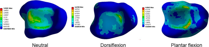
Distribution of von Mises stress in the articular surface of the distal tibia. Von Mises stress distribution of the distal tibial articular surface in neutral, dorsiflexion and plantar flexion.
3.4. Evaluation and Classification of Fracture
The five‐column classification system of Pilon fracture was proposed based on the fracture map and stress distribution, which can be described as follows. (1) Medial column fracture, medial malleolus fracture, the fracture line may extend to the proximal tibia diaphysis. (2) Anterior column fracture, nonmedial malleolus fracture of the anterior 1/3 of the distal tibial joint. (3) Posterolateral column fracture, posterior malleolus fracture. (4) Middle column fracture, the fracture line involves the posterior 2/3 of the articular surface of the distal tibia, but does not involve the medial column and posterior malleolus fracture. (5) Lateral column fracture involves the distal fibula and the inferior tibiofibular joint damage to fractures.
The fractures were evaluated by CT and 3D reconstruction, and classified using the five‐column theory. The number of each type of fracture is shown in Table 4 and Figure 7. The results included 192 cases of medial column fracture, 180 cases of middle column fracture, 165 cases of lateral column fracture, 51 cases of anterior column fracture, and 23 cases of posterolateral column fracture. Among the fractures, 32 cases were single‐column injuries, 77 cases were double‐column injuries, 113 cases were three‐column injuries, 11 cases were four‐column injuries, and 7 cases were five‐column injuries. Using the five‐column classification, the k‐weighted values of interobserver and intraobserver analysis were 0.653 (p < 0.001) and 0.708 (p < 0.001), respectively.
TABLE 4.
The number of each type of fracture.
| Affected column zones | Number | ||
|---|---|---|---|
| Single‐column fracture | Me | 16 | 32 |
| An | 2 | ||
| Mi | 14 | ||
| Double‐column fracture | Me + An | 2 | 81 |
| Me + Mi | 18 | ||
| Me + La | 33 | ||
| An + Mi | 9 | ||
| An + La | 3 | ||
| An + Po | 2 | ||
| Mi + La | 14 | ||
| Three‐column fracture | Me + An + Mi | 5 | 113 |
| Me + An + La | 6 | ||
| Me + Mi + La | 85 | ||
| An + Mi + La | 6 | ||
| Me + Mi + Po | 10 | ||
| An + Mi + Po | 1 | ||
| Four‐column fracture | Me + Mi + La + Po | 3 | 11 |
| Me + An + Mi + La | 8 | ||
| Five‐column fracture | Me + An + Mi + La + Po | 7 | 7 |
FIGURE 7.

Number of fractures per subtype. The bar graph shows the number of each subtype. Me: Medial column; An: Anterior column; Mi: Middle column; Po: Posterolateral column; and La: Lateral column.
4. Discussion
Pilon fractures are common injuries, but no comprehensive mapping study has researched all types of Pilon fractures. Furthermore, the current classifications do not represent all types of Pilon fractures and have limited significance in guiding treatment. This study analyzed fracture maps of 244 cases of Pilon fractures, conducted finite element analysis of normal ankle joints, and proposed a novel classification of Pilon fractures based on the distribution of the fracture lines and stress. The findings may help surgeons to accurately communicate the characteristics of fractures among their peers, understand the injury mechanism, and formulate surgical strategies.
4.1. Morphology of Pilon Fractures
At present, several studies have used heat maps to explore the association between fracture morphology and specific pilon fractures. Cole et al. generated a heat map of OTA/AO type 43C3 Pilon fracture [11]. However, the final result was still a 2D image of a specific section plane. Other fracture map studies on malleolus fractures were limited to posterior malleolus fractures [9, 10, 24]. In contrast, this study included all types of pilon fractures. The resulting heat map directly illustrates the distribution of fracture lines. The majority of fracture lines on the distal tibial articular surface exhibited a V‐shape. One branch was close to the medial malleolus and extended to the medial malleolus, while the other branch ran from the middle of the peroneal notch to the rear of the medial malleolus and extended to the tibial cadre. The results revealed that most of the fractures were mainly caused by axial force. The fibula fracture line mainly runs from the anterior and lower part of the lateral malleolus to the posterior and upper part. These findings can assist surgeons in statistically determining the common locations of fracture lines, thereby optimizing the design of implants. Additionally, the heat map can serve as a theoretical basis for establishing biomechanical or finite element models of pilon fracture specimens. Yu et al., Quan et al., and Phillip et al. have drawn posterior malleolus fracture maps. Compared to the results of this study, the fracture line of a simple posterior malleolus fracture tended to be more inclined toward the posterolateral articular surface, but the shape of the fracture line was similar [10, 25, 26]. Su et al. drew a map of 112 posterior malleolus fractures, suggesting that the fracture lines of the fibula originated from the lower end of the fibula before extending upwards along the anterior‐to‐posterior portion at an oblique angle; the fracture line of the tibia is mainly distributed in the medial malleolus and the posterior part of articular surface [24]. These findings are similar to our research.
4.2. Finite Element Analysis
This study indicated that when vertical loads were applied from the upper ends of the tibia and fibula to the vertical, dorsiflexed, and plantarflexed models, the stress on the posterolateral column was low, which indicated that the fractures in the posterolateral column area were not caused by vertical forces, but were caused by pull‐torsion forces. The study by Bian et al. also reached similar results [27].
4.3. Novel Classification of Pilon Fractures
This study proposes a five‐column classification based on fracture morphology and stress distribution. In the heat map, the articular surface of the medial malleolus and the inferior articular surface of the tibia were divided by a branch, so the medial malleolus was defined as the medial column. The other branch extends from the middle of the peroneal notch to the posterior aspect of the medial malleolus, defining this region as the middle column. The anterior portion of the middle column was defined as the anterior column (anterior 1/3 of the articular surface of the distal tibia). The distal fibula and inferior tibiofibular joint are defined as the lateral column. In addition, this study suggests a difference in the injury mechanism of posterior Pilon fracture and posterior malleolar fracture. Therefore, the posterolateral column was added. Posterior malleolus fractures and posterior Pilon fractures were described as two completely different fractures. Therefore, in the five‐column classification, the posterior malleolar fracture was defined as a fracture occurring in the posterolateral column to distinguish the posterior malleolus fracture from the posterior Pilon fracture. The fracture line of the posterior Pilon fracture should be located in the posterior portion of the middle column, showing signs of impact and compression on the articular surface of the tibial and talus. In such cases, the fracture fragments are more likely to involve the posterior ankle articular surface and displace proximally, resulting in step formation [27]. Conversely, posterior malleolus fractures do not involve the posterior load‐bearing articular surface of the ankle, exhibiting no signs of impact or compression on the posterior distal tibial and talus articular surfaces, and lack vertical force [27]. The boundary between the lateral column and the intermediate column was defined based on the heat map and cloud map of stress. Firstly, the last lateral point and the most anterior medial point of the distal tibial articular surface were determined. The boundary was perpendicular to the connecting line of the two points and was located at 1/6 (Figure 4b).
Ideally, fracture classification systems should be simple, reliable, and reproducible [8]. In this study, three observers evaluated fractures using the five‐column classification and then pooled their results to analyze interobserver and intraobserver agreement. Interobserver and intraobserver reliability analysis of fracture classification showed that the k values (95% confidence interval) were 0.639 (0.57–0.71) and 0.841, respectively, p < 0.01. The results revealed good interobserver and intraobserver reliability.
4.4. The Significance of Novel Classification in the Treatment of Pilon Fractures
Compared to the existing classification systems for Pilon fractures, the five‐column classification demonstrates high consistency, is easy to remember, and facilitates the communication of fracture morphology among surgeons. Furthermore, the five‐column classification encompasses nearly all types of Pilon fractures and for the first time distinguishes between posterior malleolus fractures and posterior Pilon fractures. In addition, Moreover, the five‐column classification can also provide a basis for the selection of surgical approaches. A single approach can be chosen for single‐column fractures, such as the lateral approach for lateral column fracture, the medial approach for medial column fractures, the anterior approach for anterior column fracture, and the posteromedial approach for middle column fracture. For double‐column fractures, choose an approach as far as possible to complete the operation. The posteromedial approach can be selected for a middle column fracture combined with a posterolateral column fracture, the anterior approach can be performed for an anterior column fracture combined with a middle column fracture, and an anterolateral approach can be selected for a medial column fracture combined with an anterior column fracture. For complex fractures such as three‐column and four‐column fractures, most of the operations can be completed by a double approach (Figure 8). When performing a dual incision, a minimum 7 cm skin bridge is required, which is thought to minimize the risk of soft tissue compromise and wound complications [28]. In addition, if a talus fracture or cartilage injury requires treatment, forceful plantar flexion of the ankle can expose the talus.
FIGURE 8.

The intervals for the standard surgical approaches for Pilon fractures. The intervals for the standard surgical approaches for Pilon fractures including anteromedial (A), anterior (B), anterolateral (C), medial (D), posteromedial (E), posterolateral fibula (F), and posterolateral tibia (G).
Pilon fractures are intra‐articular fractures and the main treatment of most Pilon fractures is open reduction and internal fixation [29]. The operation promotes articular surface anatomical reduction, which is beneficial to early functional exercise. The medial column can be fixed with a screw or plate, and the anterior column and middle column with a distal “T” shaped supporting plate. If combined with posterior malleolus fracture, the screw angle and length from anterior to posterior should meet the stability of the posterolateral column, and the fracture of the lateral column should be fixed with a fibula supporting plate [30, 31].
4.5. Strengths and Limitations
This study presents, for the first time, a comprehensive heat map illustrating all types of Pilon fractures, analyzing the morphological characteristics of these fractures. This may provide a theoretical basis for future designs of implants and preoperative strategies for Pilon fractures. Furthermore, based on the morphological features of Pilon fractures and the stress distribution across the distal tibial articular surface, this study proposes a five‐column classification system for Pilon fractures. The five‐column classification not only differentiates between posterior malleolus fractures and posterior Pilon fractures but also demonstrates good consistency and reproducibility, facilitating the communication of fracture morphology among surgeons. Additionally, the five‐column classification can serve as a basis for selecting surgical approaches for Pilon fractures.
Nevertheless, the limitations of the current study should be acknowledged. First, this study employed a retrospective design with qualitative evaluation methods rather than quantitative. Second, the data of this study originated from a single center, and different regions, races, and social development levels may be potential influencing factors, which should be considered in future research. The heat map derived from this study can provide some valuable information for clinical and experimental work. Long‐term follow‐up s are still lacking, so further research should investigate whether the five‐column classification can effectively evaluate injury and guide treatment.
4.6. Prospects of Clinical Application
The fracture mapping technique consumes a substantial amount of time during the reconstruction of fracture models. In the future, the application of artificial intelligence to fracture mapping technology could automate the processes of model reconstruction and fracture line delineation, thereby significantly enhancing research efficiency. Furthermore, the significance of the five‐column classification of Pilon fractures for surgical decision‐making and prognostic assessment requires validation in future clinical studies.
5. Conclusions
In this study, the morphological characteristics of Pilon fractures were clarified in detail by 3D mapping. This provides a basis for optimizing the internal fixation design of Pilon fracture, establishing a novel classification and biomechanical model of Pilon fracture. The five‐column classification system of Pilon fracture was established based on the analysis of the morphological characteristics and stress distribution of Pilon fracture. The classification may assist surgeons in accurately communicating the characteristics of fractures among their peers, understanding the injury mechanism, and formulating surgical strategies.
Author Contributions
Ji‐Chao Liu and Zheng‐Wei Li designed the study. Cheng‐Dong Piao, Guan‐Lu Cui, and Hai‐Peng Sun collected and analyzed the data. Ji‐Chao Liu and Cheng‐Dong Piao wrote the paper. Zheng‐Wei Li contributed to the manuscript editing. All authors have read and approved the submitted manuscript.
Ethics Statement
The study was approved by the Medical Ethics Committee of the Second Hospital of Jilin University (approval number: 2024020).
Conflicts of Interest
The authors declare no conflicts of interest.
Acknowledgments
The authors have nothing to report.
All authors meet the authorship criteria according to the latest guidelines of the International Committee of Medical Journal Editors, and all authors are in agreement with the manuscript.
Data Availability Statement
The data set is managed by Beijing Jishuitan Hospital. To request data access, please contact the corresponding author.
References
- 1. Flett L., Adamson J., Barron E., et al., “A Multicentre, Randomized, Parallel Group, Superiority Study to Compare the Clinical Effectiveness and Cost‐Effectiveness of External Frame Versus Internal Locking Plate for Complete Articular Pilon Fracture Fixation in Adults,” Bone & Joint Open 2, no. 3 (2021): 150–163. [DOI] [PMC free article] [PubMed] [Google Scholar]
- 2. Bedi A., Le T. T., and Karunakar M. A., “Surgical Treatment of Nonarticular Distal Tibia Fractures,” Journal of the American Academy of Orthopaedic Surgeons 14, no. 7 (2006): 406–416. [DOI] [PubMed] [Google Scholar]
- 3. Topliss C. J., Jackson M., and Atkins R. M., “Anatomy of Pilon Fractures of the Distal Tibia,” Journal of Bone and Joint Surgery. British Volume 87, no. 5 (2005): 692–697. [DOI] [PubMed] [Google Scholar]
- 4. Mauffrey C., Vasario G., Battiston B., Lewis C., Beazley J., and Seligson D., “Tibial Pilon Fractures: A Review of Incidence, Diagnosis, Treatment, and Complications,” Acta Orthopaedica Belgica 77, no. 4 (2011): 432–440. [PubMed] [Google Scholar]
- 5. Tang X., Tang P. F., Wang M. Y., et al., “Pilon Fractures: A New Classification and Therapeutic Strategies,” Chinese Medical Journal, Peking 125, no. 14 (2012): 2487–2492. [PubMed] [Google Scholar]
- 6. Yeramosu T., Satpathy J., P. W. Perdue, Jr. , et al., “Risk Factors for Infection and Subsequent Adverse Clinical Results in the Setting of Operatively Treated Pilon Fractures,” Journal of Orthopaedic Trauma 36, no. 8 (2022): 406–412. [DOI] [PMC free article] [PubMed] [Google Scholar]
- 7. L. S. Wilson, Jr. , Mizel M. S., and Michelson J. D., “Foot and Ankle Injuries in Motor Vehicle Accidents,” Foot & Ankle International 22, no. 8 (2001): 649–652. [DOI] [PubMed] [Google Scholar]
- 8. Leonetti D. and Tigani D., “Pilon Fractures: A New Classification System Based on CT‐Scan,” Injury 48, no. 10 (2017): 2311–2317. [DOI] [PubMed] [Google Scholar]
- 9. Liu Y., Lu H., Xu H., et al., “Characteristics and Classification of Medial Malleolar Fractures,” Bone & Joint Journal 103‐b, no. 5 (2021): 931–938. [DOI] [PubMed] [Google Scholar]
- 10. Quan Y., Lu H., Xu H., et al., “The Distribution of Posterior Malleolus Fracture Lines,” Foot & Ankle International 42, no. 7 (2021): 959–966. [DOI] [PubMed] [Google Scholar]
- 11. Cole P. A., Mehrle R. K., Bhandari M., and Zlowodzki M., “The Pilon Map: Fracture Lines and Comminution Zones in OTA/AO Type 43C3 Pilon Fractures,” Journal of Orthopaedic Trauma 27, no. 7 (2013): e152–e156. [DOI] [PubMed] [Google Scholar]
- 12. Glen L. Z. Q., Wong J. Y. S., Tay W. X., et al., “Weber Ankle Fracture Classification System Yields Greatest Interobserver and Intraobserver Reliability Over AO/OTA and Lauge‐Hansen Classification Systems Under Time Constraints in an Asian Population,” Journal of Foot and Ankle Surgery 62, no. 3 (2023): 505–510. [DOI] [PubMed] [Google Scholar]
- 13. Palma J., Villa A., Mery P., et al., “A New Classification System for Pilon Fractures Based on CT Scan: An Independent Interobserver and Intraobserver Agreement Evaluation,” Journal of the American Academy of Orthopaedic Surgeons 28, no. 5 (2020): 208–213. [DOI] [PubMed] [Google Scholar]
- 14. Ramos L. S., Gonçalves H. M., Freitas A., Oliveira M. P., Lima D. M. S., and Carmargo W. S., “Evaluation of the Reproducibility of Lauge‐Hansen, Danis‐Weber, and AO Classifications for Ankle Fractures,” Revista Brasileira de Ortopedia (Sao Paulo) 56, no. 3 (2021): 372–378. [DOI] [PMC free article] [PubMed] [Google Scholar]
- 15. Krettek C. and Bachmann S., “Pilon Fractures. Part 1: Diagnostics, Treatment Strategies and Approaches,” Der Chirurg 86, no. 1 (2015): 87–101, quiz 2‐4. [DOI] [PubMed] [Google Scholar]
- 16. Liu Q., Zhang K., Zhuang Y., Li Z., Yu B., and Pei G., “Analysis of the Stress and Displacement Distribution of Inferior Tibiofibular Syndesmosis Injuries Repaired With Screw Fixation: A Finite Element Study,” PLoS One 8, no. 12 (2013): e80236. [DOI] [PMC free article] [PubMed] [Google Scholar]
- 17. Zhu Z. J., Zhu Y., Liu J. F., Wang Y. P., Chen G., and Xu X. Y., “Posterolateral Ankle Ligament Injuries Affect Ankle Stability: A Finite Element Study,” BMC Musculoskeletal Disorders 17 (2016): 96. [DOI] [PMC free article] [PubMed] [Google Scholar]
- 18. Oken O. F., Yildirim A. O., and Asilturk M., “Finite Element Analysis of the Stability of AO/OTA 43‐C1 Type Distal Tibial Fractures Treated With Distal Tibia Medial Anatomic Plate Versus Anterolateral Anatomic Plate,” Acta Orthopaedica et Traumatologica Turcica 51, no. 5 (2017): 404–408. [DOI] [PMC free article] [PubMed] [Google Scholar]
- 19. Anderson D. D., Goldsworthy J. K., Li W., James Rudert M., Tochigi Y., and Brown T. D., “Physical Validation of a Patient‐Specific Contact Finite Element Model of the Ankle,” Journal of Biomechanics 40, no. 8 (2007): 1662–1669. [DOI] [PMC free article] [PubMed] [Google Scholar]
- 20. Rho J. Y., Hobatho M. C., and Ashman R. B., “Relations of Mechanical Properties to Density and CT Numbers in Human Bone,” Medical Engineering & Physics 17, no. 5 (1995): 347–355. [DOI] [PubMed] [Google Scholar]
- 21. Thompson S. M., Yohuno D., Bradley W. N., and Crocombe A. D., “Finite Element Analysis: A Comparison of an All‐Polyethylene Tibial Implant and Its Metal‐Backed Equivalent,” Knee Surgery, Sports Traumatology, Arthroscopy 24, no. 8 (2016): 2560–2566. [DOI] [PubMed] [Google Scholar]
- 22. Landis J. R. and Koch G. G., “The Measurement of Observer Agreement for Categorical Data,” Biometrics 33, no. 1 (1977): 159–174. [PubMed] [Google Scholar]
- 23. Spetzger U., Frasca M., and König S. A., “Surgical Planning, Manufacturing and Implantation of an Individualized Cervical Fusion Titanium Cage Using Patient‐Specific Data,” European Spine Journal 25, no. 7 (2016): 2239–2246. [DOI] [PubMed] [Google Scholar]
- 24. Su Q. H., Liu J., Zhang Y., et al., “Three‐Dimensional Computed Tomography Mapping of Posterior Malleolar Fractures,” World Journal of Clinical Cases 8, no. 1 (2020): 29–37. [DOI] [PMC free article] [PubMed] [Google Scholar]
- 25. Yu T., Zhang Y., Zhou H., and Yang Y., “Distribution of Posterior Malleolus Fracture Lines in Ankle Fracture of Supination‐External Rotation,” Orthopaedics & Traumatology, Surgery & Research 107, no. 6 (2021): 103000. [DOI] [PubMed] [Google Scholar]
- 26. Mitchell P. M., Harms K. A., Lee A. K., and Collinge C. A., “Morphology of the Posterior Malleolar Fracture Associated With a Spiral Distal Tibia Fracture,” Journal of Orthopaedic Trauma 33, no. 4 (2019): 185–188. [DOI] [PubMed] [Google Scholar]
- 27. Bian L., Liu P., Yuan Z., and Sha Y., “Stereo Information of Skeletal Data Based on CT Sequence Medical Images,” Journal of Infection and Public Health 13, no. 12 (2020): 2049–2054. [DOI] [PubMed] [Google Scholar]
- 28. Howard J. L., Agel J., Barei D. P., Benirschke S. K., and Nork S. E., “A Prospective Study Evaluating Incision Placement and Wound Healing for Tibial Plafond Fractures,” Journal of Orthopaedic Trauma 22, no. 5 (2008): 299–305, discussion 305‐306. [DOI] [PubMed] [Google Scholar]
- 29. Zelle B. A., Dang K. H., and Ornell S. S., “High‐Energy Tibial Pilon Fractures: An Instructional Review,” International Orthopaedics 43, no. 8 (2019): 1939–1950. [DOI] [PubMed] [Google Scholar]
- 30. Bear J., Rollick N., and Helfet D., “Evolution in Management of Tibial Pilon Fractures,” Current Reviews in Musculoskeletal Medicine 11, no. 4 (2018): 537–545. [DOI] [PMC free article] [PubMed] [Google Scholar]
- 31. Borens O., Kloen P., Richmond J., Roederer G., Levine D. S., and Helfet D. L., “Minimally Invasive Treatment of Pilon Fractures With a Low Profile Plate: Preliminary Results in 17 Cases,” Archives of Orthopaedic and Trauma Surgery 129, no. 5 (2009): 649–659. [DOI] [PubMed] [Google Scholar]
Associated Data
This section collects any data citations, data availability statements, or supplementary materials included in this article.
Data Availability Statement
The data set is managed by Beijing Jishuitan Hospital. To request data access, please contact the corresponding author.