

ABSTRACT
Objective
To evaluate the effect of three heating guns—Phasor (Vista Apex, Racine, USA), VisCalor (VOCO, Cuxhaven, Germany), and Compex HD (AdDent Inc. Danbury, USA)—on the temperature changes of two bulk‐fill resin‐based composites (RBCs): VisCalor Bulk (VBF, VOCO) and Filtek One Bulk Fill Restorative (OBF, Solventum, St. Paul, USA).
Materials and Methods
Temperature changes were measured using a thermal camera (PI 640i, Optris Infrared Measurements, Berlin, Germany) during insertion and photocuring in a simulated proximal box of a Class II cavity and within the RBC capsules during heating. The RBCs were photocured using the Bluephase PowerCure (Ivoclar, Schaan, Liechtenstein) for 20s. Data were analyzed using repeated measures ANOVA and Tukey's test for each RBC (α = 0.05). The temperature of the RBCs at the same depth were analyzed by t‐test (α = 0.05).
Results
OBF heated with Compex produced the lowest temperature rise at the pulpal floor (2.7°C ± 0.4°C), while VBF heated with Phasor produced the highest (8.8°C ± 2.4°C). The greatest temperature increases were at the top of the restoration. OBF heated with Phasor reached 48.6°C ± 4.7°C. The Phasor and VisCalor produced two temperature peaks in the RBC inside the capsule, while the Compex maintained a steady peak temperature.
Conclusion
The heating gun and RBC produced different temperatures when heating, inserting, and light‐activation of the RBCs.
Clinical Significance
The choice of RBC and heating gun can substantially affect the temperature of the RBC and influence its handling properties.
Keywords: heating, photocuring of dental resins, resin‐based composite, thermography
1. Introduction
With the global phase‐down of dental amalgam [1], resin‐based composites (RBCs) have become the primary material used for direct restorations. These RBCs are typically light‐activated using a light‐curing unit (LCU) [2] and are placed in increments of up to 2 mm thick for conventional RBCs, or up to 5 mm thick for bulk‐fill RBCs. These bulk‐fill RBCs allow for larger increments due to their use of alternative photoinitiators [3] or due to their greater translucency [4], which increases the amount of light reaching the bottom of the RBC [3, 5].
Bulk‐fill RBCs are available in regular paste consistency or low‐viscosity flowable options. Bulk‐fill flowable RBCs offer better adaptation to the cavity wall, and some produce less shrinkage stress than conventional flowable RBCs [6]. However, their mechanical properties and wear resistance are usually less than those of paste consistency RBCs due to their lower filler content [7, 8]. Therefore, they should be capped with a regular paste consistency RBC. In contrast, paste viscosity bulk‐fill RBCs have superior mechanical properties [8] and do not need to be capped with another RBC. However, they may not adapt to the cavity walls as effectively as flowable RBCs. Some, but not all, regular viscosity RBCs can be heated to 54°C–68°C before placement [9, 10, 11] to improve their flowability. This improves their adaptation to the cavity walls [12, 13] and may reduce shrinkage stress and microleakage of some RBCs [14, 15] without affecting their mechanical advantages.
Previous studies have shown that increasing the temperature of the RBC improves monomer conversion [16, 17, 18], increases the polymerization rate, and can shorten exposure times [17]. However, the RBC cools rapidly after being inserted into the cavity [10, 11]. Thus, the outcomes from in vitro studies that did not test the properties of heated composites after they had been placed into the tooth may not reflect how these RBCs respond after they have been placed, contoured, and then photocured in the tooth.
Several commercial heating guns are available to warm RBCs. The Calset (AdDent Inc. Danbury, CT, USA) is a conventional composite warmer that heats the RBC to 68°C [19]. Then, the RBC must be removed from the heater and placed onto a dispensing pad or into a conventional dispensing gun before being put into the cavity. This all takes time, and it has been reported that after heating with the Calset, the temperature of the RBC after filling the cavity was only 0.8°C above the baseline temperature [10]. This heater also takes approximately 11 min to heat the RBC [11]. Battery‐operated composite guns can directly warm the RBC inside the capsule to 50°C–70°C in just 70 s [14] and can maintain the temperature of the RBC inside the capsule as it is delivered to the tooth. The VisCalor (VOCO) heating gun is specifically designed to be used with VisCalor and VisCalor Bulk RBCs that are also made by VOCO. These VOCO RBCs are thermoviscous and are intended to be used after heating. As they cool, these RBCs return to a regular viscosity for sculpting and contouring [20]. According to the manufacturer, the VisCalor RBCs quickly cool to body temperature after placing in the tooth [20], and good clinical success rates have been reported after 24 months in the mouth [21].
Although heating the RBC improves its flowability, monomer conversion and may also reduce shrinkage stress [14, 16, 17], there are concerns regarding its potential to increase pulp temperature beyond acceptable levels. Several factors, including heat from the LCU [22, 23, 24] and the exothermic nature of polymerization [25], can further increase the pulp temperature [26]. A study correlating pulp temperature and subsequent pathological conditions in rhesus monkeys showed that a 5.5°C increase in the pulp temperature caused pulpal necrosis in 15% of the cases [27]. Based on these findings and the lack of human‐based trials, an increase of 5.5°C or more has been considered to be the potentially damaging threshold for the pulp. Some in vivo studies have shown that some LCUs and some photocuring techniques can exceed this 5.5°C threshold [22, 28, 29]. Although this risk may be further increased when heated RBCs are used with RBC guns due to the combined effects of heating, exothermic polymerization, and photocuring, to date, there is no information available regarding the influence of these heating guns on the temperature of the RBC inside the cavity. Therefore, understanding the effect of brands of heating guns on the temperature of the RBC inside the cavity and the surrounding tooth structures is required.
This study shall measure the temperature increase in two bulk‐fill RBCs using three different RBC heating guns. The null hypotheses are:
The temperature inside the RBC capsule will not differ among different heating guns.
The brand of heating gun does not affect the temperature of the RBC in the cavity preparation before photocuring.
The brand of RBC does not affect the temperature of the RBC in the heating gun.
2. Materials and Methods
2.1. Overall Study Design
Three composite heating guns were tested: Phasor (Vista Apex, Racine, WI, USA), VisCalor (VOCO, Cuxhaven, Germany), and Compex HD (AdDent Inc. Danbury, CT, USA) (Figure 1). All three composite heating guns were battery‐operated, with the VisCalor and Phasor sharing very similar designs. Table 1 reports the settings tested in this study and the maximum temperatures achieved by the heating guns as specified by the manufacturers: The number of times each heating gun could be used before the battery was discharged was also recorded.
FIGURE 1.
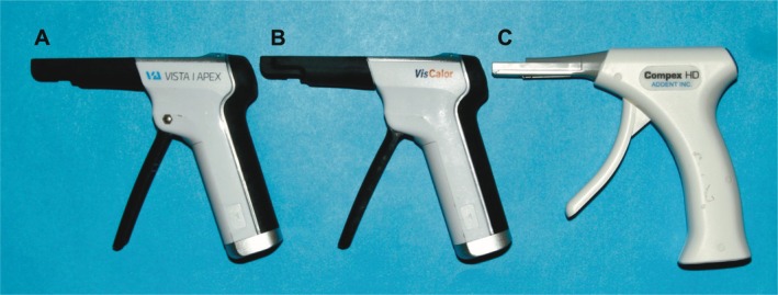
Heating gun tested: (A) Phasor, (B) VisCalor, and (C) Compex HD. Note the similar appearance of the Phasor and VisCalor.
TABLE 1.
Settings used for the different heating guns and maximum temperatures according to the manufacturers.
| Group | Heated composite delivery system | Reference number | Setting | Maximum temperature reached in (°C) | Heating time (in seconds) | RBC |
|---|---|---|---|---|---|---|
| Control‐OBF | Not applicable | Not applicable | Not applicable | Not applicable | Not applicable | Filtek One Bulk Fill |
| Control‐VBF | Not applicable | Not applicable | Not applicable | Not applicable | Not applicable | VisCalor Bulk |
| Phasor‐OBF | Phasor | 408,800 | Setting 3 | 65°C | 45‐s | Filtek One Bulk Fill |
| VisCalor‐OBF | VisCalor Dispenser | 9143 | Setting 2 | 65°C | 70‐s | Filtek One Bulk Fill |
| Compex HD‐OBF | Compex | 130,093 | Standard setting | 68°C | 40‐s | Filtek One Bulk Fill |
| Phasor‐VBF | Phasor | 408,800 | Setting 4 | 65°C | 70‐s | VisCalor Bulk |
| VisCalor VBF | VisCalor Dispenser | 9143 | Setting 1 | 65°C | 30‐s | VisCalor Bulk |
| Compex HD‐VBF | Compex | 130,093 | Standard setting | 68°C | 40‐s | VisCalor Bulk |
Two RBCs were used: VisCalor Bulk (VBF, VOCO) and Filtek One Bulk Fill Restorative (OBF, Solventum, St. Paul, MN, USA). Table 2 shows the RBCs and their composition provided by the manufacturers [30, 31]. Each RBC was photocured using the Bluephase PowerCure (Ivoclar, Schaan, Liechtenstein) in its high‐power mode (power: 596 mW; irradiance: 1124 mW/cm2) for 20 s at a 0‐mm distance. The power output from this LCU was measured three times using a fiber optic spectrometer (Flame‐T, Ocean Insight, Orlando, FL, USA) connected to an integrating sphere (Labsphere, North Sutton, NH, USA) that had been previously calibrated using an internal calibration lamp (ICS‐600, Labsphere). The test groups are described in Table 1.
TABLE 2.
| RBC | Manufacturer | Shade | LOT | Composition |
|---|---|---|---|---|
| VisCalor Bulk (VBF) | VOCO | A2 | 2,136,453 | Bisphenol‐A‐glycidyl dimethacrylate (Bis‐GMA) (10%–25% by weight), aliphatic dimethacrylate (2.5%–5% by weight). Inorganic filler wt. 83. |
| Filtek One Bulk Fill (OBF) | Solventum | A1 | NA26611 | Silane treated ceramic (60%–70% by wt.), aromatic urethane dimethacrylate (10%–20% by wt.), diurethane dimethacrylate (UDMA) (1%–10% by wt.), silane treated silica (1%–10% by wt.), ytterbium fluoride (YbF3) (1%–10% by wt.), water (< 5% by wt.), silane treated zirconia (< 5% by wt.), 1, 12‐dodecane dimethacrylate (DDDMA) (< 2.5% by wt.), ethyl 4‐dimethyl aminobenzoate (EDMAB) (< 0.3% by wt.). |
2.2. Temperature Measurements of the RBC Inside the Capsule
To measure the temperature inside the capsule, the end of the RBC capsule was cut off using a razor blade (Figure 2). A thermal camera (PI 640i, Optris Infrared Measurements, Berlin, Germany) was positioned in front of the capsule while it was in the heating gun, and temperature measurements of the RBC were taken at six specific positions at the end of the capsule. One measurement involved adding a circle in the software to encompass all of the RBC inside the capsule. The maximum temperature within this circle recorded as the ‘“composite area” measurement. Additional measurement points were placed at the center of the RBC, 1.5 mm above and below the center, and 1.5 mm to the right and left of the center (Figure 2). The initial baseline temperature for each measurement started at approximately 23°C (room temperature). The peak temperature (PT) and ΔT were measured using the same RBC capsule (n = 3) for each heating gun. Where the manufacturers' recommended settings were not the same for each RBC, VBF was also tested using the same settings as OBF for a fair comparison between these RBCs (setting 3).
FIGURE 2.

Capsules with the thermal camera measurement points marked. Note the slightly different diameters of the capsules (VBF—5 mm internal diameter; OBF—4 mm internal diameter). Each point represents a measurement point in the software. The circle is the measurement point of the “composite area.” Additional temperature measurements were collected 1.5 mm from each other in a radial pattern using the center measurement point as a reference.
2.3. Temperature Measurements Using the Thermal Camera
One half of a 3D‐printed plastic lower molar tooth was used for all the thermal measurements to standardize the mold's cavity dimensions and thermal properties. The tooth simulated the proximal box of a Class II restoration, and it was printed using a 3D Printer (Asiga Pty Ltd. Alexandria, Australia) using DentaModel (Asiga Pty Ltd.) resin. The cavity dimensions were 5 mm deep, 5 mm buccal‐lingually, and 3 mm mesio‐distally. The tooth was positioned on a warming plate (Cimarec, Thermo Fisher Scientific, Waltham, USA) set to 32°C to simulate a clinical scenario [32]. Figure 3A shows how this sectioned tooth was positioned in front of a thermal camera (PI 640i, Optris Infrared Measurements). Before inserting the RBC, a thin layer of hydrophilic gel (KY, Semina Indústria e Comércio Ltda., Sao Paulo, SP, Brazil) was applied to the cavity walls to facilitate the removal of the RBC after testing [33]. Each RBC was heated according to its test group (Table 1), inserted into the cavity, and photocured. The manufacturer of the VisCalor heating gun advises against using its gun with other brands of RBC. It states [34] that setting 1 should be used only for VBF (VisCalor‐VBF) and setting 2 for other composites from VOCO. In contrast, the Compex HD only had one temperature setting for both RBCs (Compex HD—OBF and Compex HD‐VBF). It was recommended that setting 3 on the Phasor [35] be used for OBF (Phasor‐OBF) and setting 4 for VBF (Phasor‐VBF). To use VBF used as the control group, this RBC was inserted directly from the capsule into the cavity after heating. The RBC was protected from light as it cooled and returned to the baseline temperature (32°C), at which point the RBC was photocured (Table 1). This protocol was used because VBF must be warmed before use.
FIGURE 3.

Tooth setup and designated measurement points for thermal camera temperature measurements. In (A) the tooth is on a heating plate to maintain a baseline temperature of 32°C. (B) indicated the measurement points:1 mm below the pulpal floor (−1 mm), pulpal floor (PF), and 1 mm, 2 mm, 3 mm, 4 mm, and 5 mm above the pulpal floor.
The thermal camera recorded the temperature at a frame rate of 32 Hz and temperature changes up to 125°C. The PT and temperature change from the baseline (ΔT) were recorded at the following positions: 1 mm below the pulpal floor (−1 mm), at the pulpal floor (PF), and 1 mm, 2 mm, 3 mm, 4 mm, and 5 mm above the pulpal floor, at the top of the restoration (Figure 3B). The data collected was analyzed using the Optris PIX Connected software (Optris Infrared Measurements, Berlin, Germany). For each test group, the PT and ΔT were measured. The temperature measurements started before the RBC was inserted and ended after the temperature had returned to the baseline (32°C) after photocuring. Two sets of PT and ΔT were collected: one during the insertion of the heated RBC and the other during photocuring. During data recording, the temperature scale bar was set between 25°C and 60°C, but that did not limit the temperature data collection to this range. After recording the data, a temperature versus time diagram was produced, and the temperature change from the initial temperature was determined based on the data collected.
The number of cycles each heating gun could complete before the battery was discharged was measured. The heating guns were fully charged before measurement (a green light indicated a fully charged battery when the measurement started) and they were then operated repeatedly until they turned off. The total number of heating cycles was recorded.
2.4. Statistical Analysis
Data were analyzed using SigmaPlot 13.5 (Grafiti LLC, Palo Alto, CA, USA). The normality was checked via the Shapiro–Wilk test, followed by two‐way repeated measures ANOVA and Tukey's multiple comparison test (depth vs. heating gun) for each RBC (α = 0.05). RBC temperature changes at the same depth were analyzed using t‐tests (α = 0.05).
3. Results
The Phasor and VisCalor shut off after 3 min of sustained heating, with a mean of 16 and 12 heating cycles, respectively. The Compex HD heater shut off after 10 min of run time, with a mean of 57 heating cycles.
3.1. Temperature Measurements of the RBC Inside the Capsule
Figure 4 shows representative real‐time temperatures recorded inside the capsule during the heating process. For both the Phasor‐OBF and the VisCalor‐OBF groups, the PTs recorded within the “composite area” and 1.5 mm above the center exceeded 125°C. This was the maximum temperature that the thermal camera could record (Figure 4D,E). The temperature rise pattern of the RBCs inside the Phasor and VisCalor heating guns had two disctintive temperature peaks (Figure 4A,B,D,E). In contrast, the temperature of the RBC inside the Compex heater reached a peak and then stabilized at that temperature (Figure 4C,F).
FIGURE 4.

Peak temperature graphs of the RBC inside the capsule. In (A) Phasor‐VBF; (B) VisCalor‐VBF; (C) Compex HD‐VBF; (D) Phasor‐OBF; (E) VisCalor‐OBF and (F) Compex HD‐OBF.
The Phasor and VisCalor took approximately the same time to return to the baseline temperature after they were turned off (~400 s). For the Phasor and VisCalor, both RBCs reached a peak temperature after the warming period (40–70 s). Then they maintained this temperature for a period the manufacturers reference as the “working time,” before turning off. (Figure 4). In contrast, the Compex HD heating gun maintained the temperature at the same level for longer.
When the RBC was heated with Phasor and VisCalor, the areas with the highest temperature were the “composite area” and the 1.5 mm up location in the capsule (Figure 4A,B,D,E). However, Compex's highest temperature was the “composite area” and 1.5 mm down (Figure 4C,F).
3.2. Temperature Measurements using the Thermal Camera
Table 3 reports the temperature change inside the VBF capsule when heated using the setting recommended by the manufacturer for VBF and the setting recommended by the manufacturer for OBF. There was a statistically significant difference between the heaters (p < 0.05) when used on the manufacturer's two recommended settings. When comparing different settings in the same heater, the manufacturer's setting for the Phasor had a higher temperature increase than the setting used for OBF. The temperature of VBF using the manufacturer's recommended setting for the VisCalor heating gun was lower than the setting recommended for OBF (Table 3).
TABLE 3.
Temperature changes (ΔT in °C) of VBF inside the capsule, comparing the manufacturer's recommended setting with the setting recommended for OBF.
| Composite dispenser | Manufacturer's recommended setting for VBF | Setting recommended for OBF |
|---|---|---|
| Phasor | 51.0 (0.8) Bb | 47.4 (0.4) Aa |
| VisCalor | 40.7 (1.9) Aa | 46.4 (2.0) Ab |
Note: Different uppercase letters indicate statistical differences within the same column. Different lowercase letters indicate statistical differences within the same row. Measurement point used as reference: Overall RBC area.
Table 4 reports the mean ΔT of the test groups when the heated RBC was inserted in the cavity. The greatest temperature rise was at the 5 mm position for all measurement groups, and the lowest was at 1 mm below the PF (−1 mm). Comparing different depths and heating guns within the same RBC, when VBF was inserted into the cavity, there was no difference at the top measurement point (5 mm) between using the VisCalor (22.4°C ± 1.0°C) and the Compex (26.2°C ± 1.7°C) heaters. Table 4 shows that for OBF, the Compex HD heater produced the smallest temperature rise (17.7°C ± 5.4°C) compared to the other heating guns at the top (5 mm). For both RBCs, the temperature was consistently greater at the top of the restoration (point “5 mm”) compared to the bottom of the restoration (measurement points “1 mm”, “PF” and “−1 mm”). No matter which heating gun was used, there were no significant differences between VBF and OBF at −1 mm. However, the Phasor heater produced a higher temperature increase for VBF (8.8°C ± 2.4°C) at the PF than the VisCalor heating gun and the Compex HD heaters (Table 4).
TABLE 4.
Mean temperature rise (ΔT) in °C (standard deviation) at the measurement points as the heated RBCs were inserted into the cavity.
| VisCalor Bulk | |||||||
|---|---|---|---|---|---|---|---|
| −1 mm | PF | 1 mm | 2 mm | 3 mm | 4 mm | 5 mm | |
| Phasor |
3.7 (1.0) A, e |
8.8 (2.4) A, d |
15.4 (3.4) A, c |
20.5 (1.1) A, c |
26.1 (5.0) A, b |
29.3 (5.4) A, a, b |
32.0 (2.6) A, a |
| VisCalor |
1.5 (0.4) A, d |
3.2 (0.7) B, d |
4.4 (1.3) B, c, d |
8.9 (1.1) C, c |
14.4 (0.8) B, b |
20.2 (2.1) B, a |
22.4 (1.0) B, a |
| Compex HD |
2.0 (0.3) A, d |
4.0 (1.1)B, c, d |
8.8 (2.6) B, c |
15.4 (3.4) B, b |
23.4 (3.4) A, a |
25.5 (2.3) A, a |
26.2 (1.7) B, a |
| Filtek One Bulk Fill | |||||||
|---|---|---|---|---|---|---|---|
| −1 mm | PF | 1 mm | 2 mm | 3 mm | 4 mm | 5 mm | |
| Phasor |
3.3 (1.2) A, f |
6.9 (2.1) A, e, f |
11.4 (4.6) A, B, e |
17.5 (6.0) A, d |
30.4 (3.9) A, c |
38.9 (4.1) A, b |
48.6 (4.7) A, a |
| VisCalor |
3.7 (0.4) A, f |
7.2 (0.7) A, f |
16.4 (2.3) A, e |
22.2 (3.5) A, d |
32.0 (2.6) A, c |
39.0 (2.3) A, b |
46.6 (4.3) A, a |
| Compex HD |
1.5 (0.2) A, d |
2.7 (0.4) A, d |
3.9 (0.5) B, d |
6.5 (0.7) B, c, d |
9.9 (1.4) B, b, c |
13.8 (3.9) B, a, b |
17.7 (5.4) B, a |
Note: Different letters (uppercase within column; lowercase within row for each RBC) indicate statistical differences (p < 0.001).
Figure 5 illustrates the temperature patterns observed after the RBCs were inserted using the different heating guns. The temperature was consistently higher at the top of the restoration (5 mm) than at the bottom. The reference temperature shown in the images represents the temperature at the pulpal floor (measurement point PF). The largest temperature rises were for the Phasor‐VBF, Phasor‐OBF, and VisCalor‐OBF groups (Figure 5A,D,E).
FIGURE 5.

Representative temperature rise (in °C) during RBC insertion. In order from (A) to (F): Phasor‐VBF, VisCalor‐VBF, Compex HD‐VBF, Phasor‐OBF, VisCalor—OBF and Compex HD‐OBF.
Figure 6 illustrates representative graphs of ΔT during the insertion of the RBCs. Comparing the two RBCs at the same depth for the different heating guns at the bottom of the restoration (measurement points −1 mm, PF, and 1 mm), the temperature was similar for both RBCs when using the Phasor (Figure 6A) and the Compex HD (Figure 6C) heating guns. When the VisCalor was used, the temperature varied between the two RBCs at the same depths (Figure 6B).
FIGURE 6.

Temperature changes (ΔT) during insertion of both RBCs at the same depth into the RBC produced by the different heating guns: (A) Phasor; (B) VisCalor; (C) Compex HD.
When comparing different RBCs at the same depth during insertion, there was a higher temperature increase for OBF than VBF at the top (5 mm point), except when the Compex HD heater was used (Figure 6). At the 1 mm point for OBF, the Compex HD heating gun produced the lowest temperature rise (3.9°C ± 0.5°C). This was not significantly different from Compex HD‐VBF (Figure 6). For VBF at 1 mm, the VisCalor heating gun produced the lowest temperature rise (4.4°C ± 1.3°C). Figure 6 illustrates that at the top of the cavity (5 mm), Phasor‐OBF had the highest temperature increase (48.6°C ± 4.7°C). This was significantly different from Phasor‐VBF (32.0°C ± 2.6°C).
For all RBCs, the initial temperature was consistently lower at the beginning of insertion as the RBC first entered the cavity than at the end. The Video S1 illustrates the heating pattern within the capsule as the VisCalor‐OBF group was being delivered.
The rise in temperature during photocuring of the RBC is reported in Table 5. Evaluating the different heating guns and depths within the RBC, the pulpal floor measurement points (1 mm, PF and − 1 mm) for VBF, the group with the highest temperature rise during photocuring was Phasor‐VBF (10.9°C ± 0.2°C at −1 mm, 20.2°C ± 1.6°C at PF and 25.0°C ± 0.4°C at 1 mm). For OBF, there were no statistical differences between the composite heating guns and the control group at points −1 mm and PF. At 1 mm, the Phasor and VisCalor heating guns produced higher temperature increases (25.5°C ± 2.6°C for Phasor and 28.1°C ± 2.7°C for the VisCalor) compared to the Compex HD and the control group (18.0°C ± 1.1°C for Compex and 17.3°C ± 1.2°C for the control group). At the top of the restoration (point 5 mm), OBF, when used with both Phasor (44.8°C ± 3.1°C) and VisCalor (42.6°C ± 1.9°C) heating guns, had the highest temperature rise when compared to the other groups. For VBF, there was no statistical difference in the temperature rise of the three composite heating guns, and all produced a greater temperature rise than the control group (20.4°C ± 0.1°C).
TABLE 5.
Mean temperature rise (ΔT) in °C (standard deviation) of the experiment groups at all measurement points when photo‐activated for 20s.
| VisCalor Bulk | |||||||
|---|---|---|---|---|---|---|---|
| −1 mm | PF | 1 mm | 2 mm | 3 mm | 4 mm | 5 mm | |
| Control (unheated RBC) | 6.8 (0.7) B, d | 13.0 (0.7) B, c | 15.1 (0.2) B, b, c | 16.2 (0.5) C, b | 18.0 (0.3) C, a, b | 19.7 (0.4) C, a | 20.4 (0.1) B, a |
| Phasor | 10.9 (0.2) A, e | 20.2 (1.6) A, d | 22.4 (1.5) A, c, d | 25.0 (0.4) A, c | 28.0 (1.1) A, b | 29.9 (1.1) A, a, b | 32.3 (2.1) A, a |
| VisCalor | 8.3 (0.5) B, e | 15.2 (1.1) B, d | 17.3 (1.3) B, c, d | 20.2 (1.1) B, b, c | 22.7 (1.2) B, a, b | 27.0 (1.9) B, a | 30.4 (0.4) A, a |
| Compex HD | 7.9 (0.1) B, f | 13.0 (1.0) B, e | 17.4 (0.8) B, d | 22.8 (2.9) A, c | 25.6 (1.8) A, b, c | 28.4 (0.9) A, B, a, b | 30.3 (1.5) A, a |
| Filtek One Bulk Fill | |||||||
|---|---|---|---|---|---|---|---|
| −1 mm | PF | 1 mm | 2 mm | 3 mm | 4 mm | 5 mm | |
| Control (unheated RBC) | 8.1 (0.8) A, f | 15.1 (0.7) A, e | 17.3 (1.2) B, d, e | 19.7 (1.2) B, c, d | 21.5 (1.7) B, b, c | 24.3 (0.6) B, a, b | 27.9 (1.0) B, a |
| Phasor | 9.8 (1.0) A, g | 17.6 (2.2) A, f | 25.5 (2.6) A, e | 29.7 (2.4) A, d | 34.6 (1.4) A, c | 39.0 (2.2) A, b | 44.8 (3.1) A, a |
| VisCalor | 8.8 (0.5) A, f | 15.1 (1.3) A, e | 28.1 (2.7) A, d | 32.3 (2.8) A, c | 36.0 (0.2) A, b, c | 38.9 (3.1) A, a, b | 42.6 (1.9) A, a |
| Compex HD | 8.0 (0.7) A, f | 14.5 (1.0) A, e | 18.0 (1.1) B, d, e | 20.7 (0.8) B, c, d | 23.0 (1.4) B, b, c | 26.6 (3.2) B, a, b | 28.5 (4.6) B, a |
Note: Different uppercase letters indicate statistical differences in the same column (p < 0.001). Different lowercase letters indicate statistical differences within the same row for each RBC.
Figure 7 illustrates the ΔT increases of the RBCs during the photocuring process. The graphs show the comparison between the two RBCs at the same depth for each heating gun. For the Compex HD, there was a statistically significant difference between the RBCs at the 3 mm depth only (Figure 7D). In contrast, when light curing after using the Phasor heating gun, temperature differences were noted for each RBC at all depths (Figure 7B). Significant differences between RBCs were observed in the control group at all measurement points except at the PF and at 1 mm (Figure 7A). For the VisCalor heating gun, temperature differences were noted at all measurement points except at the bottom (−1 mm and PF) (Figure 7C).
FIGURE 7.

Temperature changes (ΔT) (°C) of both RBCs at the same depths for the different composite heating guns when photo‐cured for 20s: (A) Control; (B) Phasor; (C) VisCalor; (D) Compex HD.
4. Discussion
Heating the RBC lowers its viscosity and improves its adaptation to the cavity [9]. Gun‐style heating guns are easier to use than conventional dispensers and take less time to heat the RBC [14, 36]. This study analyzed the temperature increase in two bulk‐fill RBCs using three heating guns. The real‐time temperature of the heated RBCs was divided into three moments: inside the RBC capsule when it was in the heating gun, when the RBC was inserted in the tooth cavity, and during photocuring.
The first hypothesis that the temperature inside the RBC capsule would not differ between the different heating guns was rejected because the temperature rise inside the capsule (Figure 4) increased differently depending on the RBC and composite heating gun used. The Compex HD delivered more consistent temperatures than the other two heating guns, and maintained a stable temperature for both RBCs (Figure 4C,F). The Compex HD had one of the lowest increases in temperature when the RBCs were inserted in the cavity (Table 4). The temperature that the RBC reached inside the gun may explain this temperature rise. This difference in the heating pattern can be related to the design of the RBC heating gun. Unlike the Phasor and VisCalor, which heat the RBC from the top, the Compex HD gun heats the capsule from the bottom. The battery in the Compex gun lasted the longest (mean of 57 applications per charge) compared to the VisCalor and Phasor (12‐16 uses). This difference may be attributed to the battery used or the fact that the VisCalor and the Phasor heating guns offeri multiple heating settings, which could contribute to a faster battery discharge.
The manufacturers of the heating guns claim that their product heats up to 65°C or 68°C (Table 1). However, the current findings suggest that the temperature inside the capsule is not uniform (Figure 4). The differences in heating patterns significantly affected the temperature of the RBCs at the measured points inside the capsule (Figure 4). When the Phasor and VisCalor guns heated OBF, the top measurement points that were closest to the heat source reached a temperature that was beyond the thermal camera's maximum recording temperature. In contrast, the bottom point reached temperatures closer to the manufacturer's specified value of 65°C (Figure 4). The same happened with VBF, with the temperature in the measurement point closer to the heating area of the gun reaching a higher temperature than the measurement point that was furthest from the heating area (Figure 4). Although a dentist may use the VisCalor heating gun with other brands of RBC, the manufacturer does not indicate that it can be used with other brands of RBCs, only with different RBCs from VOCO [34]. This could be why the temperature increase inside the capsule of OBF (Figure 4B) was greater. However, the same heating pattern happened for the Phasor‐OBF group, with the areas closest to the heating spot (Figure 4). The design of the Phasor and Viscalor heating guns was quite similar and it influenced the heating pattern of the RBCs. Since heat is known to reduce the viscosity of RBCs [37], the uneven heat distribution within the capsule will cause different areas of the composite to reach varying viscosities and temperatures, potentially altering the material's properties. Excessive heat could also cause the plastic capsules to melt during use, which occurred in some instances during the study. During temperature measurements, both RBCs were found to be less viscous and cooler at the beginning of insertion compared to the end (Figure 5). Also, the composite heat gradient within the capsule may be related to the geometry of the capsule itself and how it is positioned in the dispenser. Further studies on the viscosity changes of these RBCs under different heating patterns are warranted.
The manufacturers of the Phasor and VisCalor heating guns recommend different settings for different RBCs, but the Compex HD does not. These settings most likely affected the heating patterns. Notably, when VBF was analyzed using the same settings as OBF (Table 3), the temperature of the VBF was lower than when its recommended setting was used on the Phasor heating gun (Table 3). When VBF was analyzed using the same setting as OBF with the VisCalor heating gun (Table 3), the temperature was higher than the manufacturer's recommended setting for VBF. This discrepancy may be attributed to the length of the heating cycle in the gun because the heating cycle on Setting 1 on the VisCalor gun that is intended to be used only on Viscalor Bulk lasts 30 s, while Setting 2 intended for use only on other RBCs from VOCO has one heating cycle lastsing 70 s (Table 2).
The specific heat of a material is defined as the amount of heat required to increase the temperature of 1 g of a substance by 1°C, and this property is related to the filler content [38]. OBF had a lower filler content (Table 1) than VBF, and its lower specific heat may be why this RBC achieved higher temperature increases, sometimes reaching higher temperatures than the manufacturer's claimed temperature (68°C) inside the capsule. Also, notable differences were observed in how the capsules of the two RBCs were heated during the experiments. The OBF capsule consistently absorbed more heat than the VBF capsule, resulting in a greater temperature increase in OBF and some melting of the OBF capsules. There are significant differences in the geometry and plastic materials used to make composite capsules from different manufacturers. Unfortunately, there are currently no regulatory standards for these parameters. Future studies are required to test the effect of heating on other brands of capsules with the same test protocol.
The second hypothesis that the brand of the heating gun does not affect the temperature of the RBC in the cavity preparation before photocuring was rejected because there were differences in the temperature increase when comparing the temperatures at different depths within the cavity and when comparing the different composite heating guns (Table 4, Figure 6). The fact that the RBC temperature was higher than 65°C in multiple areas inside OBF's capsule (Figure 4) may have influenced the greater temperature rise during the insertion of the RBC, sometimes reaching temperatures higher than the threshold (5.5°C) at the bottom of the cavity (Table 4, Figure 6B). The greatest temperature rise was at the top of the RBC (5 mm). The lowest was at 1 mm, at the pulpal floor, and 1 mm below the pulpal floor (1 mm, PF and −1 mm) for all measurement groups when the heated RBCs were inserted into the simulated proximal box of a Class II cavity (Table 4, Figure 6). This is in agreement with previous studies that reported a rapid fall in the temperature of the RBC after it was inserted into the cavity [10, 11, 14] due to the heat dissipation when the RBC touches the cavity walls [22]. The lower temperature at the bottom may also result from the cooler RBC at the tip of the capsule when it was inserted into the cavity. This RBC at the tip of the capsule, did not contact the composite heating gun, and it was colder than other parts of the capsule. As shown in Figure 5, the temperature at the bottom of the restoration at the end of insertion was close to baseline (32°C) (Figure 5). Therefore, the first 1–2 mm of RBC from the capsule should be discarded when using these RBC heating guns.
When the RBCs were light‐cured, the temperature at the top of the RBC closest to the tip of the LCU was always higher than at the bottom of the cavity (Table 5). Even when comparing RBCs inserted with different heating guns, the temperature differences at the bottom of the cavity were always less pronounced than those observed at the top (Table 5, Figure 6). This means that, although the temperature increased during the insertion of heated RBCs, the ΔT at the bottom was not as affected by heating as much as the temperature at the top of the RBC. The greater temperature increase at the top of the restoration can be attributed to heat from the LCU [22]. Previous in vitro studies showed that intrapulpal temperature increases when placing heated RBCs between 54°C and 68°C are considered safe [39, 40]. During the insertion of heated RBCs, none of the groups produced a mean temperature rise exceeding 5.5°C at −1 mm below the PF in the plastic tooth (Table 4). However, when the heated RBCs were photo‐activated, all the groups produced a greater temperature rise than the control unheated RBC (Table 5). A previous study also reported that heated RBCs produced a greater temperature increase when photocuring in dentin [41]. When comparing temperature rise during light activation at the same depth, it is noteworthy that for Compex HD (Figure 7D), there was no significant difference in temperature rise between the two RBCs. Furthermore, compared to the control group (Table 5), the temperature rise was similar to that of the unheated RBC.
This study compared the performance of different brands of composite heating guns. The Phasor and VisCalor heating guns had multiple settings with varying heating durations (Table 1), while the Compex HD offered only onesetting. Clinicians may not always be aware of the differences between these heating guns and their settings, highlighting the importance of understanding these variations. For example, the Phasor heating gun has four settings, while the VisCalor offers two. Selecting an incorrect setting, which can easily happen when turning the heater on, can significantly affect the RBC's temperature increase and heating pattern. Although this study did not examine multiple heating guns from the same brand, and therefore no broad generalizations can be made, the Compex HD heating gun performed better than the others in this study. It exhibited a more consistent heating pattern and had a longer battery life, with a mean of 57 applications percharge. This was shorter than the 100 cycles claimed by the manufacturer, but longer than the other two heating guns tested. However, multiple examples of the guns should be tested to verifiy if a difference truly exists between brands.
The RBCs evaluated included a thermoviscous RBC that is designed and marketed to be heated (VBF) and an RBC that the manufacturer states can be heated (OBF). When VBF was used with its designated heating gun (the VisCalor Heating gun) or with the Compex HD, there was a smaller increase in temperature during placement (Table 4, Figure 4B). For OBF, the Compex HD heating gun resulted in lower temperature increases during RBC placement and inside the capsule (Table 4, Figure 4C). Additionally, the VBF produced more consistent temperature increases inside the capsule than OBF (Figure 4), likely due to the specific design of the capsule and the fact that the VBF capsule is designed to be heated. Therefore, the third hypothesis, which stated that the brand of RBC does not affect the temperature of the RBC in the heating gun, was rejected. For the VisCalor heating gun, OBF and VBF behaved differently when comparing the RBCs at the same depth (Figure 6B). For Phasor and Compex HD heating guns, the temperature increase was similar at the bottom but not at the top (Figure 6A,C). Researchers should measure the temperature of RBCs when using heating guns, because different heating guns and RBCs can delivered different temperatures. Additionally, clinicians must know whether the composite and its capsule they are using is intended to be heated. For instance, VBF composites are specifically designed for heating, but many manufacturers do not state this information in their instructions for use or make capsules that can be heated.
The same plastic tooth was used for all the measurements in the study. This standardized the test conditions, and a baseline starting temperature of 32°C was used. This represented the approximate value inside a human pulp of a prepared tooth after etching and rinsing, followed by photocuring of the bonding agent [32]. It is important to highlight that the temperature measurements in this study focused on the RBC rather than the tooth structure. The temperature differences between settings and heating guns may have clinical implications, including an increased risk of pulp necrosis [27]. Therefore, further studies are necessary in human teeth to evaluate the impact of pulp flow when using heated RBC, and because the thermal diffusivity of enamel/dentin differs from that of the plastic tooth.
5. Conclusion
With the limitations of the study that used the same resin tooth for all the experiments, it was concluded that:
The brand of heating gun and RBC influenced the temperature rise when inserting the heated RBC into a cavity;
The temperature during the insertion of the heated RBCs was considered safe for the surrounding tooth structures;
The temperature rise inside the capsule followed different patterns depending on the make of the capsule, the RBC, and the heating gun. The temperature inside the capsule sometimes exceeded 65°C.
Conflicts of Interest
The authors declare no conflicts of interest.
Supporting information
Video S1. Temperature of OBF RBC during the beginning and end of insertion inside the cavity.
Acknowledgments
This study was financed in part by the Coordenação de Aperfeiçoamento de Pessoal de Nível Superior—Brasil (CAPES)—Finance Code 001 and by the Mitacs grants (#IT40995 and #IT42399).
Funding: This work was supported by Mitacs (#IT40995 and #IT42399); Coordenação de Aperfeiçoamento de Pessoal de Nível Superior ‐ Brazil (CAPES) ‐ Finance Code 001.
Data Availability Statement
The data that support the findings of this study are available from the corresponding author upon reasonable request.
References
- 1. FDI World Dental Federation , “FDI Policy Statement on Dental Amalgam and the Minamata Convention on Mercury: Adopted by the FDI General Assembly: 13 September 2014, New Delhi, India,” International Dental Journal 64, no. 6 (2014): 295–296. [DOI] [PMC free article] [PubMed] [Google Scholar]
- 2. Rueggeberg F. A., Giannini M., Arrais C. A. G., and Price R. B. T., “Light Curing in Dentistry and Clinical Implications: A Literature Review,” Brazilian Oral Research 31, no. suppl 1 (2017): e61. [DOI] [PubMed] [Google Scholar]
- 3. Price R. B. T., “Light Curing in Dentistry,” Dental Clinics of North America 61, no. 4 (2017): 751–778. [DOI] [PubMed] [Google Scholar]
- 4. Son S.‐A., Park J.‐K., Seo D.‐G., Ko C.‐C., and Kwon Y. H., “How Do Light Attenuation and Filler Content Affect the Microhardness and Polymerization Shrinkage and Translucency of Bulk‐Fill Composites?,” Clinical Oral Investigations 21, no. 2 (2017): 559–565. [DOI] [PubMed] [Google Scholar]
- 5. Ilie N., “The Dependence on Hue, Value and Opacity of Real‐Time‐ and Post‐Curing Light Transmission in a Nano‐Hybrid Ormocer,” Materials (Basel) 17, no. 2 (2024): 496. [DOI] [PMC free article] [PubMed] [Google Scholar]
- 6. Ilie N. and Hickel R., “Investigations on a Methacrylate‐Based Flowable Composite Based on the SDR Technology,” Dental Materials 27, no. 4 (2011): 348–355. [DOI] [PubMed] [Google Scholar]
- 7. de Deus R. A., Oliveira L., Braga S., et al., “Effect of Radiant Exposure on the Physical and Mechanical Properties of 10 Flowable and High‐Viscosity Bulk‐Fill Resin Composites,” Operative Dentistry 49, no. 2 (2024): 136–156. [DOI] [PubMed] [Google Scholar]
- 8. Van Ende A., De Munck J., Lise D. P., and Van Meerbeek B., “Bulk‐Fill Composites: A Review of the Current Literature,” Journal of Adhesive Dentistry 19, no. 2 (2017): 95–109. [DOI] [PubMed] [Google Scholar]
- 9. Lopes L. C. P., Terada R. S. S., Tsuzuki F. M., Giannini M., and Hirata R., “Heating and Preheating of Dental Restorative Materials‐A Systematic Review,” Clinical Oral Investigations 24, no. 12 (2020): 4225–4235. [DOI] [PubMed] [Google Scholar]
- 10. Daronch M., Rueggeberg F. A., Hall G., and De Goes M. F., “Effect of Composite Temperature on In Vitro Intrapulpal Temperature Rise,” Dental Materials 23, no. 10 (2007): 1283–1288. [DOI] [PubMed] [Google Scholar]
- 11. Daronch M., Rueggeberg F. A., Moss L., and de Goes M. F., “Clinically Relevant Issues Related to Preheating Composites,” Journal of Esthetic and Restorative Dentistry 18, no. 6 (2006): 340–350. [DOI] [PubMed] [Google Scholar]
- 12. Andrade A. C. M., Trennepohl A. A., Moecke S. E., Borges A. B., and Torres C. R. G., “Viscosity Modulation of Resin Composites Versus Hand Application on Internal Adaptation of Restorations,” Clinical Oral Investigations 26, no. 7 (2022): 4847–4856. [DOI] [PubMed] [Google Scholar]
- 13. Demirel G., Orhan A., Irmak O., et al., “Effects of Preheating and Sonic Delivery Techniques on the Internal Adaptation of Bulk‐Fill Resin Composites,” Operative Dentistry 46, no. 2 (2021): 226–233. [DOI] [PubMed] [Google Scholar]
- 14. Hordones Ribeiro M. T., Felipe de Braganca G., Sales Oliveira L. R., et al., “Effect of Pre‐Heating Methods and Devices on the Mechanical Properties, Post‐Gel Shrinkage, and Shrinkage Stress of Bulk‐Fill Materials,” Journal of the Mechanical Behavior of Biomedical Materials 138 (2023): 105605. [DOI] [PubMed] [Google Scholar]
- 15. Wagner W. C., Aksu M. N., Neme A. M., Linger J. B., Pink F. E., and Walker S., “Effect of Pre‐Heating Resin Composite on Restoration Microleakage,” Operative Dentistry 33, no. 1 (2008): 72–78. [DOI] [PubMed] [Google Scholar]
- 16. Daronch M., Rueggeberg F. A., De Goes M. F., and Giudici R., “Polymerization Kinetics of Pre‐Heated Composite,” Journal of Dental Research 85, no. 1 (2006): 38–43. [DOI] [PubMed] [Google Scholar]
- 17. Daronch M., Rueggeberg F. A., and de Goes M. F., “Monomer Conversion of Pre‐Heated Composite,” Journal of Dental Research 84, no. 7 (2005): 663–667. [DOI] [PubMed] [Google Scholar]
- 18. Lecamp L., Youssef B., Bunel C., and Lebaudy P., “Photoinitiated Polymerization of a Dimethacrylate Oligomer: 1. Influence of Photoinitiator Concentration, Temperature and Light Intensity,” Polymer 38, no. 25 (1997): 6089–6096. [Google Scholar]
- 19. AdDent , “Calset ‐ Composite Warmer,” 2024, https://addent.com/wp‐content/uploads/2023/02/IDSSalesFlyer_Single_CALSET_HIRES.pdf.
- 20. VOCO , “Viscalor Bulk: Thermoviscous Bulk Fill Composite,” 2024, https://www.voco.dental/en/portaldata/1/resources/products/folders/gb/viscalor‐bulk_fol_gb.pdf.
- 21. Favoreto M. W., Carneiro T. S., Naupari‐Villasante R., et al., “Clinical Performance of Preheating Thermoviscous Composite Resin for Non‐Carious Cervical Lesions Restoration: A 24‐Month Randomized Clinical Trial,” Journal of Dentistry 144 (2024): 104930. [DOI] [PubMed] [Google Scholar]
- 22. Runnacles P., Arrais C. A., Pochapski M. T., et al., “In Vivo Temperature Rise in Anesthetized Human Pulp During Exposure to a Polywave LED Light Curing Unit,” Dental Materials 31, no. 5 (2015): 505–513. [DOI] [PubMed] [Google Scholar]
- 23. Maucoski C., Price R. B., Sullivan B., Guarneri J. A. G., Gusso B., and Arrais C. A. G., “In‐Vitro Pulpal Temperature Increases When Photo‐Curing Bulk‐Fill Resin‐Based Composites Using Laser or Light‐Emitting Diode Light Curing Units,” Journal of Esthetic and Restorative Dentistry 35, no. 4 (2023): 705–716. [DOI] [PubMed] [Google Scholar]
- 24. Maucoski C., Price R. B., Arrais C. A. G., and Sullivan B., “In Vitro Temperature Changes in the Pulp Chamber Caused by Laser and Quadwave LED‐Light Curing Units,” Odontology 111, no. 3 (2023): 668–679. [DOI] [PubMed] [Google Scholar]
- 25. Balestrino A., Verissimo C., Tantbirojn D., Garcia‐Godoy F., Soares C. J., and Versluis A., “Heat Generated During Light‐Curing of Restorative Composites: Effect of Curing Light, Exotherm, and Experiment Substrate,” American Journal of Dentistry 29, no. 4 (2016): 234–2240. [PubMed] [Google Scholar]
- 26. Lau X. E., Liu X., Chua H., Wang W. J., Dias M., and Choi J. J. E., “Heat Generated During Dental Treatments Affecting Intrapulpal Temperature: A Review,” Clinical Oral Investigations 27, no. 5 (2023): 2277–2297. [DOI] [PMC free article] [PubMed] [Google Scholar]
- 27. Zach L. and Cohen G., “Pulp Response to Externally Applied Heat,” Oral Surgery, Oral Medicine, and Oral Pathology 19, no. 4 (1965): 515–530. [DOI] [PubMed] [Google Scholar]
- 28. Gross D. J., Davila‐Sanchez A., Runnacles P., et al., “In Vivo Temperature Rise and Acute Inflammatory Response in Anesthetized Human Pulp Tissue of Premolars Having Class V Preparations After Exposure to Polywave(R) LED Light Curing Units,” Dental Materials 36, no. 9 (2020): 1201–1213. [DOI] [PubMed] [Google Scholar]
- 29. Zarpellon D. C., Runnacles P., Maucoski C., et al., “Influence of Class V Preparation on In Vivo Temperature Rise in Anesthetized Human Pulp During Exposure to a Polywave((R)) LED Light Curing Unit,” Dental Materials 34, no. 6 (2018): 901–909. [DOI] [PubMed] [Google Scholar]
- 30. VOCO , “Viscalor Bulk Safety Data Sheet,” 2024, https://www.dentalsky.com/amfile/file/download/file/1450/product/13758/.
- 31. Solventum , “Filtek One Bulk Fill Safety Data Sheet,” 2024, https://multimedia.3m.com/mws/mediawebserver?mwsId=SSSSSuUn_zu8l00xm82Bm8_ZPv70k17zHvu9lxtD7SSSSSS‐‐.
- 32. Zarpellon D. C., Runnacles P., Maucoski C., et al., “In Vivo Pulp Temperature Changes During Class V Cavity Preparation and Resin Composite Restoration in Premolars,” Operative Dentistry 46, no. 4 (2021): 374–384. [DOI] [PubMed] [Google Scholar]
- 33. Guarneri J. A. G., Chima M. V. A., Assis D. G., Rueggeberg F. A., and Arrais C. A. G., “Influence of Light Exposure Techniques on In Vitro Pulp Temperature Rise During Bulk Fill Composite Class I Restorations,” Odontology 112, no. 2 (2024): 479–488. [DOI] [PubMed] [Google Scholar]
- 34. VOCO , “Viscalor Dispenser User Manual,” 2024, https://www.voco.dental/pt/portaldata/1/resources/products/instructions‐for‐use/e1/viscalor‐dispenser_ifu_e1.pdf.
- 35. Vista Apex , “Phasor User's Manual,” 2024, https://vistaapex.com/wp‐content/uploads/2021/01/408800‐I‐V‐77‐MUL‐3.pdf.
- 36. Favoreto M. W., de Souza Carneiro T., Wendlinger M., et al., “Various Ways of Pre‐Heating a Bulk‐Fill Thermoviscous Composite in Restoration in Non‐Carious Cervical Lesions: 12‐Month Randomized Clinical Trial,” Clinical Oral Investigations 27, no. 8 (2023): 4345–4359. [DOI] [PubMed] [Google Scholar]
- 37. Loumprinis N., Maier E., Belli R., Petschelt A., Eliades G., and Lohbauer U., “Viscosity and Stickiness of Dental Resin Composites at Elevated Temperatures,” Dental Materials 37, no. 3 (2021): 413–422. [DOI] [PubMed] [Google Scholar]
- 38. Saitoh M., Masutani S., Kojima T., Saigoh M., Hirose H., and Nishiyama M., “Thermal Properties of Dental Materials—Cavity Liner and Pulp Capping Agent,” Dental Materials Journal 23, no. 3 (2004): 399–405. [DOI] [PubMed] [Google Scholar]
- 39. Karacan A. O. and Ozyurt P., “Effect of Preheated Bulk‐Fill Composite Temperature on Intrapulpal Temperature Increase In Vitro,” Journal of Esthetic and Restorative Dentistry 31, no. 6 (2019): 583–588. [DOI] [PubMed] [Google Scholar]
- 40. El‐Deeb H. A., Abd El‐Aziz S., and Mobarak E. H., “Effect of Preheating of Low Shrinking Resin Composite on Intrapulpal Temperature and Microtensile Bond Strength to Dentin,” Journal of Advanced Research 6, no. 3 (2015): 471–478. [DOI] [PMC free article] [PubMed] [Google Scholar]
- 41. Lohbauer U., Zinelis S., Rahiotis C., Petschelt A., and Eliades G., “The Effect of Resin Composite Pre‐Heating on Monomer Conversion and Polymerization Shrinkage,” Dental Materials 25, no. 4 (2009): 514–519. [DOI] [PubMed] [Google Scholar]
Associated Data
This section collects any data citations, data availability statements, or supplementary materials included in this article.
Supplementary Materials
Video S1. Temperature of OBF RBC during the beginning and end of insertion inside the cavity.
Data Availability Statement
The data that support the findings of this study are available from the corresponding author upon reasonable request.