

Abstract
Oscillating gradient spin echo (OGSE) diffusion MRI (dMRI) can probe the diffusive dynamics on short time scales , which translates into the sensitivity to tissue microstructure at the short length scales . OGSE-based tissue microstructure imaging techniques able to characterize the cell diameter and cellular density have been established in pre-clinical studies. The unique image contrast of OGSE dMRI has been shown to differentiate tumor types and malignancies, enable early diagnosis of treatment effectiveness, and reveal different pathophysiology of lesions in stroke and neurological diseases. Recent innovations in high-performance gradient human MRI systems provide an opportunity to translate OGSE research findings in pre-clinical studies to human research and the clinic. The implementation of OGSE dMRI in human studies has the promise to advance our understanding of human brain microstructure and improve patient care. Compared to the clinical standard (pulsed gradient spin echo), engineering OGSE diffusion encoding for human imaging is more challenging. This review summarizes the impact of hardware and human biophysical safety considerations on the waveform design, imaging parameter space, and image quality of OGSE dMRI. Here we discuss the effects of the gradient amplitude, slew rate, peripheral nerve stimulation, cardiac stimulation, gradient driver, acoustic noise and mechanical vibration, eddy currents, gradient nonlinearity, concomitant gradient, motion and flow, and signal-to-noise ratio. We believe that targeted engineering for safe, high-quality, and reproducible imaging will enable the translation of OGSE dMRI techniques into the clinic.
Keywords: clinical translation, high-performance gradient, microstructure, MRI system engineering, oscillating gradient, time-dependent diffusion
1 |. OVERVIEW OF OGSE METHODOLOGY
1.1 |. Which tissue building blocks would we like to become sensitive to?
Cytoarchitecture and its alternation provide fundamental information about disease identification, progression, and response to treatment.1 In oncology, the cellular size, shape, density, and composition of tissues at the length scale of are the biomarkers for tumor staging and evaluation of treatment response.2–4 For example, immune cells (such as T cells) have relatively small average radii of 2–5 μm;5 glioma cells have average radii of 4–7 μm;6–10 and cells in breast tumor,11 prostate epithelium12 and hepatocytes13 have relatively large average radii ≥6 μm (Figure 1). After treatment, cell size shrinkage (e.g., glioma radii reduction from 6 μm to ~4 μm14,15) and low tumor cell density are typical features of treatment-induced necrosis and apoptosis.16
FIGURE 1.
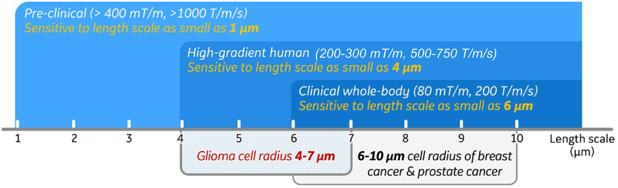
The length scales that pre-clinical, human high-performance gradient and clinical whole-body diffusion MRI are sensitive to, compared with the cell radii of different human tumors.
In neurological and neurodegenerative diseases, the integrity and density of axons, neuronal cell bodies, and dendrites are altered.17–21 For example, axonal beading (blebbing or varicosities) along the axon length,22,23 which occurs already in normal axons,24,25 becomes more pronounced in axonal injury.20,21,23 Dendritic swelling and beading have also been observed in ischemic stroke.18 These morphological changes of axons and dendrites are associated with underlying pathology such as microtubules damage in stretched nerve fibers20 and ischemia.17 Average varicosity spacing along axons has been reported to be 3–5 μm.19,23–25 Therefore, capturing abnormal beading (amplitude or spacing) at the micrometer range may identify the focal and/or global regions of tissue damages in the brain, which is a challenge in traumatic brain injury23 and other brain diseases.
With excellent soft tissue contrast that can reflect structural, functional, and molecular information, MRI is indispensable for assessing spatially heterogeneous lesions. In the clinic, the size of an MR image voxel is a few millimeters, about 100–1000 times coarser than the characteristic length scales of the relevant tissue microstructure mentioned above. Therefore, MRI contrast reflects massive averaging over water molecules experiencing different cellular environments. This is the inherent mismatch between MRI and biopsy/histopathology analysis of relatively small samples. Remarkably, water diffusion, ubiquitous in tissues, allows us to tune MRI sensitivity to micrometer-level tissue building blocks, by varying the diffusion time and weighting.26–30
1.2 |. Why is OGSE optimal to probe short diffusion times?
The fundamental relation between the diffusion length (root mean squared molecular displacement) and the diffusion time in spatial dimensions serves as a basis for probing length scales by varying the diffusion time:
| (1) |
In simple liquids, diffusion is Gaussian, and is time-independent constant; for example, for water at 37°C. In tissues, microstructural complexity makes diffusion non-Gaussian, and the mean squared displacement does not in general grow linearly with . Therefore, the diffusion coefficient becomes a function of the diffusion time . In the diffusion MRI (dMRI) literature, the cumulative diffusion coefficient is most commonly used, following Equation (1); alternatively, one can define an instantaneous . In any case, the diffusion time , as the time of the evolution of the mean squared displacement, exists irrespective of an MRI sequence. As we will discuss below, different diffusion measurements may be seen as filters imposed on the “ideal” objective diffusive dynamics of spin-carrying molecules in a given medium.
Qualitatively speaking, the characteristic scale of tissue structures that cause diffusion restriction or hindrance (e.g., cell size, the correlation length of cell packing or of axonal beading, etc) are best sensed when is matched by the diffusion length, . This equation defines the time scale to be attained for resolving tissue structure at the length scale . A more rigorous picture is that of the gradual coarse-graining of the tissue microstructure by the increasing diffusion length (Equation 1), washing out structural details finer than .28,31
The classic way to measure time-dependent is to employ pulsed gradient spin echo (PGSE)32 dMRI with narrow pulses (Figure 2A,C). In an ideal, narrow-pulse PGSE measurement, one assumes negligible displacement during the pulse duration , and the diffusion time is just the interval between the front lobes of the two pulses. Finite sets the precision for our ability to define the diffusion time. The corresponding PGSE signal attenuation involves the diffusion weighting
| (2) |
The overall scale of diffusion weighting is determined by the Larmor frequency gradient , related to the field gradient by the gyromagnetic ratio . A useful number to keep in mind is for , a maximal single-axis gradient for a state-of-the-art clinical scanner. The smallness of such nominally “strong” gradient in the microstructure units, and the fact that , explain why it is challenging to create appreciable signal attenuation if one wishes to probe the scales below . Indeed, to obtain a moderate (for a desired attenuation with in tissues, to ensure adequate precision in estimating the diffusion tensor), one has to employ sufficiently long timings and . In our example, can be reached, for example, for and . Making longer decreases the precision in defining the diffusion time, whereas increasing makes us less sensitive to small structures. In particular, based on Equation (1), probing displacements (the cell sizes relevant to clinical questions) at this is already beyond reach.
FIGURE 2.
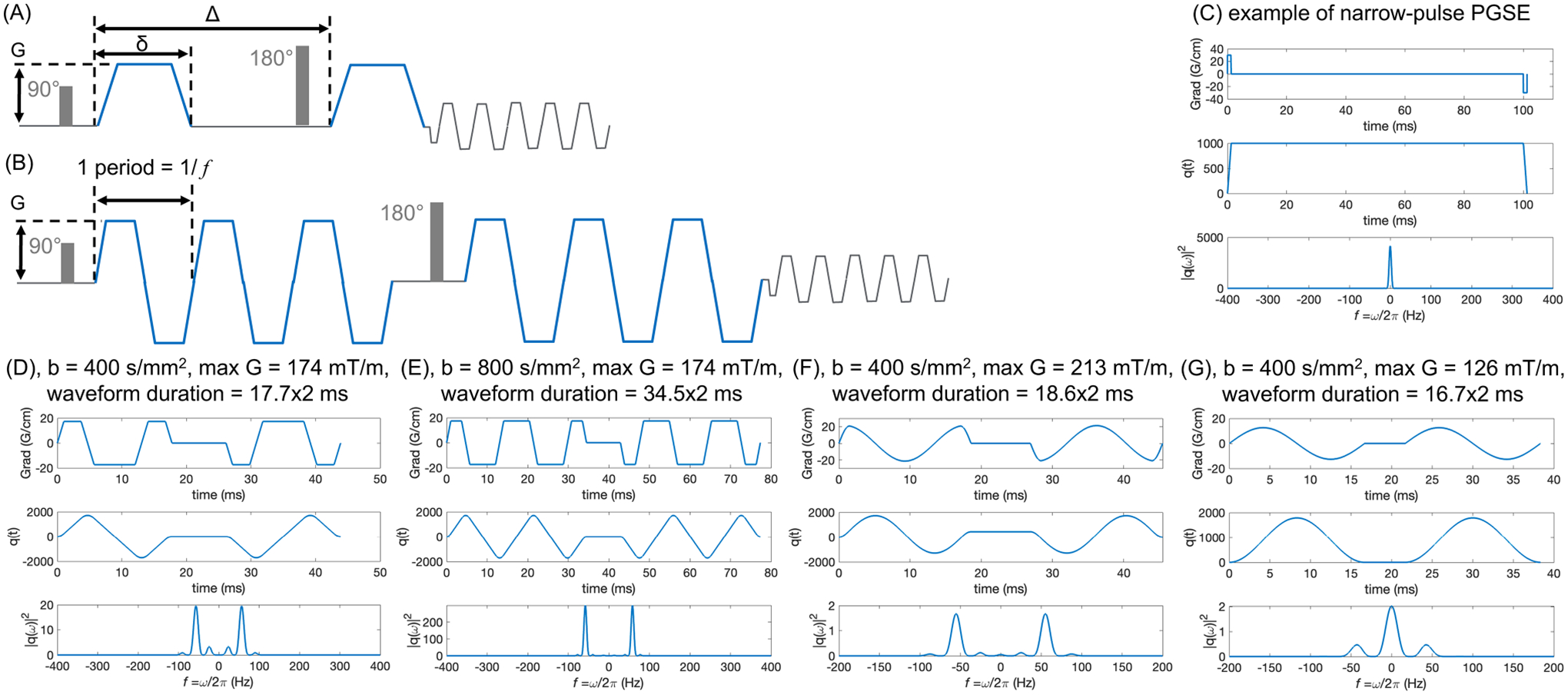
(A) and (B) show the schematic of PGSE and trapezoidal-modulated OGSE waveforms, respectively. (C–G) show PGSE waveform and different OGSE waveforms with the polarity of post-180 diffusion pulse reversed, the anti-derivative of the gradient, and its spectrum . OGSE waveforms can achieve higher -values with multiple oscillating periods (E vs. D) while maintaining the same diffusion time (or OGSE frequency), for example, at . (F) and (G) show the cosine and sine OGSE waveforms, respectively, at the same -value and frequency ranges.
Stronger gradients enable shortening both and . For example, a gradient amplitude of 200 mT/m can achieve and , allowing probing displacements ~ 10 μm. However, PGSE dMRI remains inefficient for achieving shorter diffusion times even as the gradient performance increases. Since cannot fall below , the diffusion weighting for the shortest possible diffusion times scales as . This rather unfortunate scaling makes it challenging to attain appreciable diffusion weightings at short times.
Oscillating gradient spin echo (OGSE)33,34—a train of periodically changing with frequency —saves the day by decoupling the diffusion time (of the order of the oscillation period ) from the total waveform duration of oscillations (Figure 2B). In this way, the diffusion weighting28,35,36
| (3) |
is accumulated over periods, where the single-period weighting is akin to that for PGSE with . With periods, we probe the diffusive dynamics at the shortest time scale yet enjoy an -fold increased attenuation (Equation 3), cf. examples shown in Figure 2D,E. The number , practically limited by the relaxation, separates the time scales and , thereby setting the precision of defining the oscillation frequency .
Trapezoid-cosine OGSE waveform37 (Figure 2D) has been commonly used, for its frequency selection around the designed frequency and higher -value, as compared to pure cosine waveform (Figure 2F) and pure sine waveform (Figure 2G), with the latter causing the admixture28,38 of the long-time PGSE , further complicating the analysis. Furthermore, the effective OGSE frequency of a certain waveform has been calculated in two approaches: (1) the peak frequency of the spectrum of , the anti-derivative of the gradient waveform; (2) the centroid of the spectrum (Equation 7 in Reference [39]). In this review, we refer to the peak frequency when reporting the numerical value.
1.3 |. How to select the OGSE frequency range for probing specific tissue microstructure?
A practically important question is how to select the OGSE frequency given the characteristic scale of tissue structures we would like to probe. An order of magnitude estimate for the diffusion time can be made based on the discussion after Equation (1). Our intuition then suggests to choose OGSE frequency . However, as we discuss below, the nonlocal relation between the OGSE-measured and the PGSE-measured time-dependent diffusion coefficient means that cannot in general be interpreted as . Below, we will give a few biologically relevant examples (tumors, neurodegenerative disorders), where an explicit conversion between PGSE and OGSE is possible.
We note from the outset, that and measured for all and , carry exactly the same information about the diffusion process. However, this information gets “distributed” across or differently in either quantity. PGSE measures the mean squared displacement accumulated over the entire time interval from 0 to . Hence, the cumulative accumulates all the history of the random walker’s (water molecule) displacement. In comparison, OGSE captures the diffusive dynamics at a set time scale (assuming the transient processes have died out during a large number of oscillations). In this regard, is closer to the instantaneous .
To formalize this intuition, we recall28,40 that both and are different facets of the dispersive diffusivity , which relates the Fourier components of the diffusive flux and the density gradient, , generalizing the Fick’s law. Technically, is a Fourier transform of the retarded velocity autocorrelation function of a random walker, where the unit step function at and otherwise. Applying any gradient waveform , the diffusion signal attenuation (up to ) reads26,28
| (4) |
where is the Fourier transform of . In other words, the signal is a functional of the gradient waveform , that is, a mapping of a function to a number. One can view Equation (4) as that imposes a filter of the shape on the actual .
In OGSE encoding in the limit becomes a delta function at the frequency of oscillation (Figure 2E), thereby yielding , the real part of .28
In PGSE encoding with narrow pulse, (Figure 2C), such that
| (5) |
Equation (5) and the relations between differently defined time- or frequency-dependent diffusion coefficients are summarized in Figure 6 and Section 2.2.2 of Reference [28].
FIGURE 6.
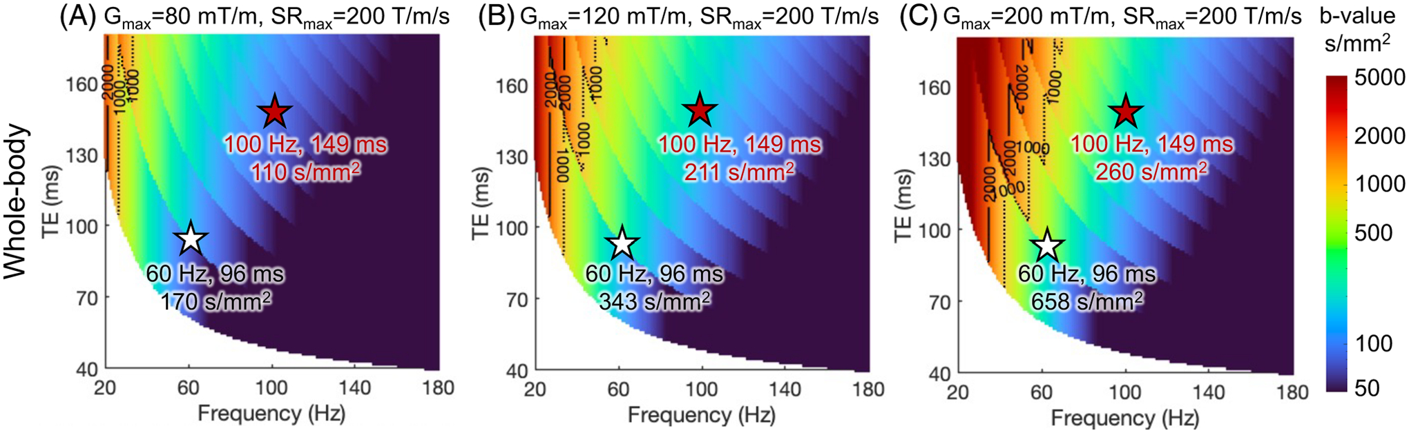
The maximum -value of trapezoid-cosine OGSE achieved at TE’s and frequencies using the gradient and slew rate constrained by both MRI system limits in Figure 4 and CS threshold of whole-body gradient coils. As an example, the CS threshold of the whole-body gradient coil is characterized with and .
The manifestly nonlocal in time/frequency relation between the ideal and (Equation 5) makes converting between in PGSE and in OGSE challenging. In particular, while and carry exactly the same information, one needs to know for all to recover for any —and vice-versa, one needs to know for all to recover for any .
In biological systems, explicit conversion between in PGSE and in OGSE is feasible for geometries for which the functional forms of the time-dependent diffusion are known. Specifically:
Short-time surface-to-volume (S/V) limit36,38,41: ,28,38 as recently observed in a fiber phantom on a clinical scanner.42 Being in a short-time limit requires the diffusion length much smaller than the cell size. In in vivo MRI, Reynaud et al.7 observed the functional form, a signature of the S/V limit, in a mouse glioma model with OGSE frequency up to 225 Hz, where the tumor cell radii ≥ 5 μm.
Long-time power-law approach28,43,44: towards the bulk diffusivity due to coarse-graining over the structural disorder corresponds to the dispersive contribution , with dependent on the disorder exponent , cf. Equation 48 in Reference [28]. In particular, the power law tail was identified43 as coming from one-dimensional structurally disordered () neurites in the normal and globally ischemic rat brain.35 The increase in this specific dispersive contribution in ischemia was interpreted as the sensitivity to the increase of the structural disorder (e.g., beading) along neurites in stroke.43 This behavior has been subsequently identified in human brain OGSE dMRI studies.39,45
Fully confined pores: The low-frequency functional forms are (first observed by Stepisnik et al.46) and , where is the pore size. This is an example where and are qualitatively different in terms of . OGSE in tumor cells assumed as impermeable spheres should exhibit this functional form.7 In this review, we use this functional form when correlating OGSE frequency and tumor cell size to illustrate the sensitivity of OGSE to tissue length scale, with .
To summarize, while our intuition suggests that OGSE at frequency should correspond to PGSE at the time scale , the essentially nonlocal relation (Equation 5) makes this correspondence non-universal (model-dependent). When we know what kind of biological system we are studying (e.g., tumor, axonal beading), it is possible to explicitly select the frequency range in OGSE and the corresponding diffusion time range in PGSE depending on the tissue length scale we want to probe.
1.4 |. From gradient performance to pre-clinical, clinical, and human research findings of OGSE dMRI
High-performance gradient is essential to OGSE dMRI.6,47 OGSE waveforms with high maximum gradient amplitude () and slew rate () are necessary to maximize the -value, especially at high OGSE frequency. Therefore, a shorter echo time (TE) and a higher signal-to-noise ratio (SNR) can be achieved.
Figure 1 shows the sensitivity of OGSE dMRI to tissue length scale at different gradient strengths. Operating at ≥400 mT/m and ≥1 000 T/m/s, OGSE dMRI in pre-clinical scanners can achieve high frequency Hz and the sensitivity to tissue length scales as small as 1 μm.13,48 The accuracy of OGSE dMRI has been well studied in animal models that evaluate MRI-measured cell size and cellularity of different tumor types validated with pathology.6–11,48–50 High accuracy has been shown in detecting cell sizes in treatment-naïve gliomas,7,10 as well as cell shrinkage after treatment.51 Furthermore, the unique image contrast of OGSE dMRI has also been shown to indicate brain pathologies including axonal beading35,43,52 and demyelination.53,54
Current clinical standard whole-body MRI systems operate at of 33–80 mT/m and of 120–200 T/m/s. They allow a maximum of 40–50 Hz OGSE frequencies,11,12,39,55–57 corresponding to a length scale limit of about 6 μm. OGSE dMRI has emerged for imaging cancer,11–13,55–59 stroke,52,60 brain maturation,61 and pediatrics.62 A thorough review of the applications can be found in Reynaud et al.,6 and Xu.63 The limited gradient performance of current clinical MRI systems may not achieve high sensitivity to short tissue length scales. Indeed, multiple studies49,50 have reported an overestimated glioma cell radii of 8–15 μm in patients.
Human high-performance gradient MRI systems operating at of 200–500 mT/m and of 200–900 T/m/s64–69 have been introduced by multiple MRI vendors and academic sites. Recent studies45,70,71 have demonstrated achieving high -value and high OGSE frequency at short TE (Figure 3) in human brain. For example, Zhu et al.71 and Michael et al.70 both showed achieving OGSE frequency ≥100 Hz, theoretically providing sensitivity to tissue length scale as small as 4 μm.72–74 These systems may best address the need for probing tissue microstructures relevant to tumors71 and brain diseases and disorders.23,25,43
FIGURE 3.
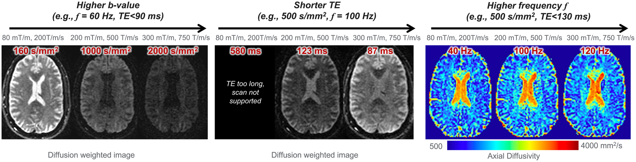
Example of human brain OGSE dMRI at different gradient configurations, including of 80 mT/m and of 200 T/m/s; of 200 mT/m and of 500 T/m/s; and of 300 mT/m and of 750 T/m/s. Images were acquired within peripheral nerve stimulation and cardiac stimulation limits in a head-only high-performance gradient MRI system.
In summary, recent system hardware innovations meet the need for high-performance gradient for OGSE dMRI in human studies. These provide opportunities to translate pre-clinical research findings to human research and the clinic. Indeed, preliminary studies have shown new image contrasts that potentially reveal tissue microstructures including cellular density, restricted tissue size, and water exchange rate in tumor patients,71 stroke patients,52 and healthy human brain.45,70,75,76 In this review, we emphasize the unique engineering challenges of OGSE dMRI when translating the technique from pre-clinical studies to human studies, and discuss the approaches to advance the translation.
2 |. IMPACTS OF SYSTEM ENGINEERING ON OGSE DMRI
Although the biophysics of OGSE dMRI has been validated in pre-clinical MRI systems, the clinical adoption of OGSE dMRI needs to address unique engineering challenges, as summarized in Table 1. In pre-clinical MRI, high image quality and accuracy in diffusion MRI measurements are achieved with high SNR, high spatial resolution, and high accuracy of magnetic gradient field. This is because the small field-of-view (FOV) of 15–40 mm makes it much easier to increase and for a given accuracy tolerance on the gradient field, as well as to ensure relatively low power consumption and high duty cycle.
TABLE 1.
Engineering challenges of human OGSE dMRI, comparing to pre-clinical OGSE dMRI and clinical whole-body PGSE dMRI.
| Section | Engineering | MRI system and diffusion encoding technique | Effect on image | ||||
|---|---|---|---|---|---|---|---|
| Pre-clinical, OGSE | Clinical whole-body, PGSE | Human whole-body, OGSE | Human head-only, OGSE | ||||
| MRI system limitation | Main magnetic field | 4.7T, 7T, 11T | 3T | 3T, 7T | 3T, 7T, 10.5T | ||
| Imaging FOV | 1.5–4 cm | 20–50 cm | 20–50 cm | 20–30 cm | |||
| 2.1 | Gradient | > 400 mT/m | 50–200 mT/m | 50–200 mT/m | 200–500 mT/m | ||
| 2.4 | Power electronics | — | High power at high b-value | High power at low b-value for high | HIgh power at low b-value for high | Imaging parameter space | |
| 2.5 | Acoustic noise and mechanical vibration | Frequency dependent | — | Frequency dependent | Frequency dependent | ||
| 2.6 | Eddy current | — | Linear 0th & 1st order terms | Nonlinear 0th & 1st order termsa | Nonlinear 0th & 1st order terms | Image quality and accuracy of quantification | |
| 2.7 | Gradient nonlinearity | Neglectable | Unneglectable for large FOV | Unneglectable for large FOV | Higher in 26-cm FOVa | ||
| 2.8 | Concomitant gradient | Neglectable | Even terms only | Even terms only | Odd & even terms; 5–40X highera | ||
| 2.9 | Motion and flow | 1st & 2nd moment nulled | Not motion-compensated | 1st & 2nd moment nulled | 1st & 2nd moment nulled | ||
| 2.10 | SNR | High | Medium | Low | Medium | ||
| Biophysical safety requirement | 2.2 | PNS threshold | Unconstrained | Whole-body coil PNS threshold | 2–5X highera | Imaging parameter space | |
| 2.3 | CS threshold | Unconstrained | Whole-body coil CS threshold | > 2.5X higher at 300 mT/ma | |||
Abbreviations: CS, Cardiac stimulation; FOV, Field-of-view; PNS, Peripheral nerve stimulation; SNR, Signal-to-noise ratio.
In comparision to whole-body, PGSE.
In human MRI, however, the MRI system limit and biophysical safety constraints affect the usable MRI parameters, such as TE, -value, OGSE frequency, and TR. We illustrate MRI system limits in the following sections including gradient performance (Section 2.1), power electronics (Section 2.4), and acoustic noise and mechanical vibration (Section 2.5). We further discuss biophysical safety constraints including peripheral nerve stimulation (PNS) (Section 2.2) and cardiac stimulation (CS) (Section 2.3). Furthermore, imaging in the ~ 10× gradient coil size inevitably leads to challenges from relatively large gradient nonlinearity, high concomitant gradient field, and high power consumption. If unaddressed, these effects compromise image quality and scan efficiency. We discuss them in the sections on eddy currents (Section 2.6), gradient nonlinearity (Section 2.7), concomitant gradient (Section 2.8), motion and flow (Section 2.9), and SNR (Section 2.10). Different engineering requirements for human versus pre-clinical MRI systems, as well as those between OGSE and PGSE, are discussed.
2.1 |. Imaging parameter space at maximum gradient performance
Recent developments of highly efficient gradient coils and high-power electronics have advanced and in human MRI systems (Table 2). In whole-body MRI systems with a bore diameter ≥ 60 cm, the majority of high-end clinical systems operate at and . Whole-body MRI systems operating at and have been achieved, which were first introduced by the Human Connectome Project.77,78 Due to limited coil efficiency, the large-bore whole-body gradient coils need very high input current ≥ 900 A and voltage ≥ 2 000 V to reach high and .79 Therefore, whole-body high-performance gradient MRI systems are enabled by high-power electronic devices. As a variety of new systems at 3T80–83 and 5T84 are becoming clinically available, whole-body high-performance gradient MRI systems will become more widely accessible to patients.
TABLE 2.
Representative human high-performance gradient MRI systems with human in vivo images published.
| Whole-body MRI system | Field strength (Tesla) | Bore size (cm) | (mT/m) | (T/m/s) |
|---|---|---|---|---|
| Prismaa (S.) | 3 | 60 | 80 | 200 |
| Premiera (G.) | 3 | 70 | 80 | 200 |
| UHP 3T (G.) | 3 | 60 | 113 | 260 |
| Jupiter (U.) | 5 | 60 | 120 | 200 |
| Cima.X (S.) | 3 | 60 | 200 | 200 |
| Connectome 1.0 (S.) | 3 | 56 | 300 | 200 |
| Head-only MRI system | Field strength (Tesla) | Gradient coil size (cm) | (mT/m) | (T/m/s) |
| Magnetom 7T Plusa (S.) | 7 | 40 | 80 | 350 |
| LH7 (A.) | 10.5 | 41 | 117 | 900 |
| MAGNUS† (G.) | 3 | 42 | 200 | 500 |
| IMPULSE (S.) | 7 | 44 | 200 | 900 |
| Achieva HPGa (P.) | 3 | 33 | 200 | 600 |
| MAGNUS 2.0a (G.) | 3 | 42 | 300 | 750 |
| Connectome 2.0 (S.) | 3 | 44 | 500 | 600 |
| Neuro Frontier (U.) | 3 | 39 | 650 | 600 |
Note: Clinical products: Siemens Prisma, GE HealthCare Premier, Siemens Cima.X, United Imaging Jupiter; Research prototypes from Siemens: Connectome 1.0, Magnetom 7T Plus, IMPULSE, Connectome 2.0; Research prototypes from GE HealthCare: UHP 3T, MAGNUS, MAGNUS 2.0; Research prototypes from Philips: Achieva HPG (high-performance gradient); Research prototypes from United Imaging: Neuro Frontier; Research prototypes from the academia: LH7. S.: Siemens; G.: GE HealthCare; U.: United Imaging; A.: The academia; P.: Philips.
OGSE images published in journal papers/abstracts.
Gradient coils with a smaller diameter of 33–44 cm but high coil efficiency have been developed and installed at 3T,64–66,69 7T,67 and 10.5T68 MRI systems. These systems can achieve up to 650 mT/m with 7 MVA input power per axis (Table 2). The small-bore gradient coils are dedicated to human brain imaging. Feasibility of human prostate imaging in these small-bore systems85 has also been demonstrated.
Figure 4 shows the maximum -values of conventional trapezoid-cosine OGSE waveforms at different TE’s and OGSE frequencies using the and of different MRI systems. The calculation is detailed in Supplementary Material S1. As increases from 80 mT/m (Figure 4A) to 200 mT/m (Figure 4C) in the whole-body MRI systems, the maximum -value at a fixed TE and OGSE frequency greatly increases. At 200 mT/m and 200 T/m/s, the relatively long ramp time prohibits operating at high OGSE frequencies (Figure 4C, Supplementary Figure S3). The higher of head-only gradient MRI systems enable higher OGSE frequencies (Figure 4D). By further pushing to 300–500 mT/m and to 600–750 mT/m, simultaneously high -value, short TE, and high OGSE frequency are achieved (Figure 4E,F).
FIGURE 4.
The maximum -value of trapezoid-cosine OGSE achieved at varying TE’s and frequencies, using simultaneous and of whole-body MRI systems (A–C) and head-only MRI systems (D–F). The calculation is detailed in Supplementary Material S1. At a fixed frequency, the maximum -value shows discontinuity at certain TE, which is due to the use of different numbers of OGSE waveform periods, as shown in Supplementary Figure S2. Other system constraints are not imposed.
The imaging parameter space at maximum gradient performance can be accessed in phantom and animal studies where the physiological risk due to the fast-switching magnetic field is absent or considered negligible.
2.2 |. Peripheral nerve stimulation
In human MRI, the operation of the gradient field is subject to biophysical safety constraints. Fast-switching magnetic fields that are generated by gradient coils induce electric fields, which can trigger uncomfortable sensations through PNS in humans. PNS constraint86 is implemented to protect human biophysical safety in MRI scans. The linear gradient field threshold curve86 is described as , where is the minimum slew rate to cause nerve stimulation at infinitely long ramp time, is the minimum gradient amplitude to cause nerve stimulation at infinitely high slew rate, and is the ramp time.
Head-only gradient coils allow a higher (~ 5×) PNS threshold87–89 compared to whole-body gradient coils. At high-gradient amplitude that is desired for diffusion encoding (e.g., 200 mT/m), the maximum slew rate applicable to human imaging is reduced to ~200 T/m/s in head-only gradient coils and 70–90 T/m/s in whole-body gradient coils due to PNS thresholds.
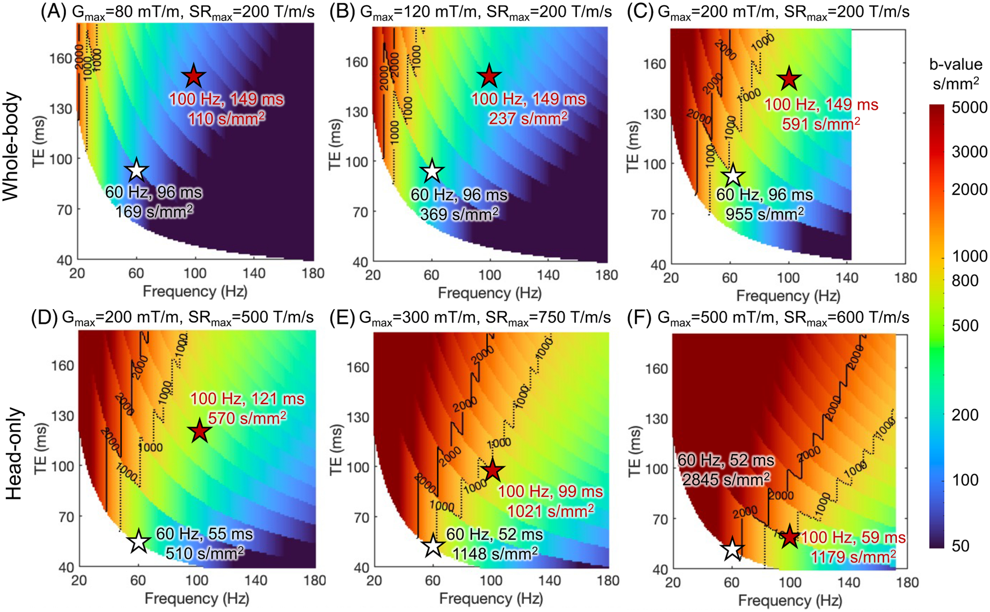
Figure 5 shows the maximum -values of trapezoid-cosine OGSE waveforms at different TEs and OGSE frequencies using the gradient and slew rate constrained by both MRI system limits and PNS threshold of gradient coils. The actual used gradient amplitude and slew rate are shown in Supplementary Figure S4. The PNS threshold reduces the maximum -value at a fixed OGSE frequency and TE (Figure 5), compared to the -value without the PNS threshold (Figure 4).
FIGURE 5.
The maximum -value of trapezoid-cosine OGSE achieved at TE’s and frequencies using the gradient and slew rate constrained by both MRI system limits in Figure 4 and PNS threshold of gradient coils. As an example in this review, the head-only gradient coils are characterized with and , in the linear gradient field threshold curve of bipolar gradients. As an example in this review, the whole-body gradient coil is characterized with and .
The PNS threshold has a high impact on the OGSE imaging space at high OGSE frequencies, which requires simultaneously high-gradient amplitude (to achieve adequate -value) and high slew rate (to achieve high frequency). At high-gradient amplitude, the slew rate within the PNS threshold is reduced, leading to a long ramp time and prohibiting high OGSE frequency. Reducing the gradient amplitude and increasing the slew rate allow OGSE gradient waveforms with high frequencies (Figure 5C), as detailed in Supplementary Figure S5. However, the achievable -value is smaller (Figure 5C vs. Figure 4C).
The high PNS thresholds of head-only gradient coils greatly expand the achievable imaging parameter space of OGSE dMRI. For example, can still be achieved at and TE= 121 ms (Figure 5D) in the head-only gradient coil with 200 mT/m and 231 T/m/s (Supplementary Figure S4D). In comparison, the -value is reduced to ≤ 200 s/mm2 at and TE= 149 ms in whole-body gradient coil (Figure 5C) with same 200 mT/m but a lower slew rate of 89 T/m/s due to PNS (Supplementary Figure S4C). At , the PNS thresholds of existing head-only gradient coils eventually limit minimum TE at high OGSE frequency and (Figures 5E,F and S4E,F).
2.3 |. Cardiac stimulation
Cardiac stimulation (CS) is another biophysical safety constraint that limits the slew rate at high-gradient amplitudes. In the clinical whole-body MRI systems with , CS is not a concern. However, it becomes an important consideration in higher-performance gradient systems.
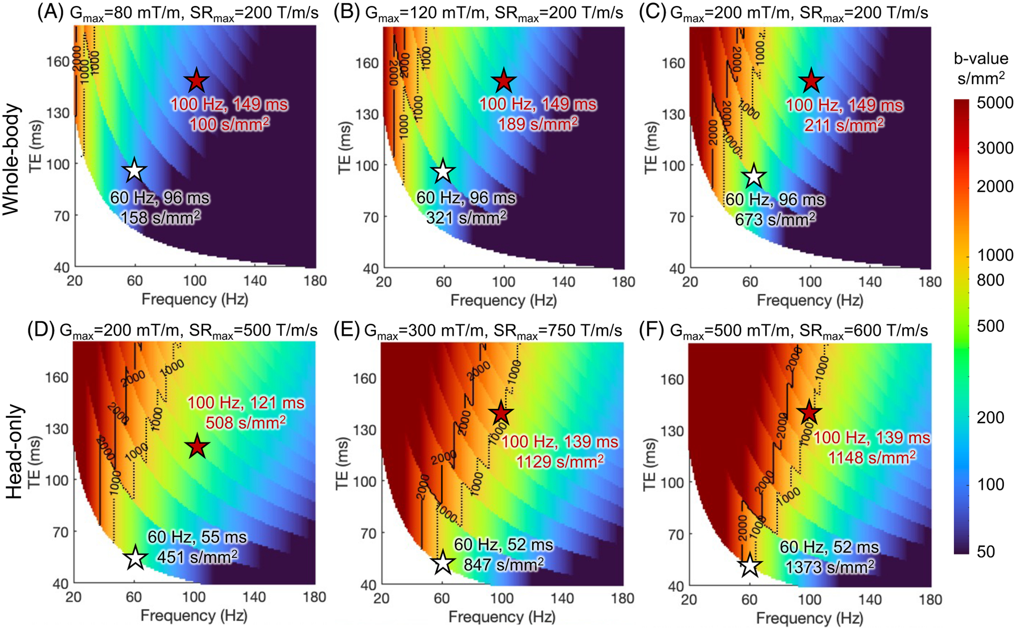
For whole-body gradient systems, the electromagnetic field in the chest and heart of a human is typically the highest at the brain imaging position.90 Through electromagnetic simulation, the chronaxie of CS has been approximated to be about one order of magnitude longer than that of PNS.91 Depending on the scan position, the CS threshold can be lower than the PNS threshold at high-gradient amplitude in whole-body systems. For example, the slew rates limited by PNS and CS in the whole-body gradient Connectome 1.0 system were estimated to be ~88 T/m/s and ~77 T/m/s at 300 mT/m, respectively (estimated from Figure 2 in Reference [91]). In other words, besides PNS, the CS threshold of whole-body gradient coils may further limit the usable slew rate when high-gradient amplitude is needed, such as in OGSE. Figure 6 shows the maximum -value at each TE and OGSE frequency using the gradient and slew rate constrained by both MRI system limits and the CS threshold of whole-body gradient coils. At low gradient amplitude (Figure 6A,B), the maximum -value is larger compared to that constrained by the PNS threshold (Figure 5A,B). At high-gradient amplitude (Figure 6C), the maximum -value at 60 Hz and TE of 96 ms becomes smaller compared to that constrained by the PNS threshold (Figure 5C), indicating that the CS threshold becomes the dominant factor limiting the maximum achievable -value.
For imaging the brain in the head-only gradient systems, the electromagnetic field in the chest and heart is greatly reduced compared to whole-body MRI systems at the brain imaging position.90,92 This is beneficial not only for the PNS threshold but also for the CS threshold, which was demonstrated by Klein et al.93 in animal experiments. The recent electromagnetic simulation by Hua et al.94 indicated that the maximum electric fields that can be generated by the MAGNUS X, Y, Z coils, individually and in three-axes combined mode, at 300 mT/m and 750 T/m/s are below the IEC 60601–2-33 CS limit. This study suggested that the CS threshold at the brain imaging position in head-only gradient systems with ≤ 300 mT/m and ≤ 750 T/m/s is higher than the PNS threshold. Therefore, the CS threshold does not further limit the OGSE dMRI parameter space beyond the PNS limitation. At higher gradient performance and/or other imaging positions, the CS threshold and its impact on OGSE dMRI need to be re-evaluated. Further studies using both animal and human body models95 are ongoing to improve our understanding of the bioelectromagnetic safety in high-performance whole-body and head-only gradient systems. With better knowledge, OGSE imaging parameter space for safe human studies may be further expanded.
2.4 |. Gradient driver
The high power consumption of diffusion MRI is a limiting factor to both the imaging parameter space and scan efficiency. The gradient field is determined by gradient coils with input currents, , which are delivered by power electronic devices including a gradient power amplifier (GPA) and a power supply (PS) for each physical gradient axis. Ohmic heating in the gradient coil and losses in the power electronic devices are summarized as gradient heating. Excessive heat must be transported away from the gradient coil and power electronic devices to avoid potential hardware damage. The removal of heating in the gradient chain is detailed in Supplementary Material S2. Therefore, it is important to illuminate the gradient heating generated by OGSE waveforms, its impact on imaging acquisition, and existing mitigation approaches.
Losses in the PS and GPA are not purely Ohmic, and the gradient coil also has frequency-dependent impedances. However, a simple resistive circuit is commonly used to approximate the Ohmic losses in the gradient system, where is the resistance of the gradient coil. The current is proportional to the gradient amplitude . Consequently, the dissipated energy during the playout period of a gradient waveform scales as
| (6) |
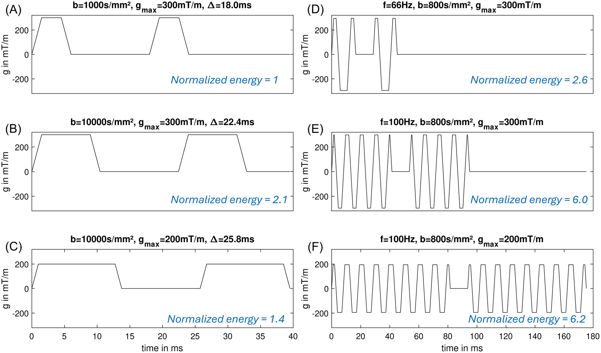
The high-gradient amplitude and long duration of the OGSE waveforms require much higher power input, compared to that of PGSE at the same -value. For example, at , an OGSE waveform at 66 Hz (Figure 7D) and 100 Hz (Figure 7E) requires 2.6× and 6.0× higher energy consumption of the PGSE waveform at (Figure 7A).
FIGURE 7.
Energy over the diffusion encoding waveforms of OGSE and PGSE.
The power consumption and heating of OGSE are more problematic in whole-body gradient systems with a larger bore size. Power is proportional to , where is the gradient coil diameter.79 For example, the same OGSE waveform at and in a 70-cm diameter bore whole-body gradient system and a 60-cm gradient system require 12.9× and 5.95× higher power, compared to that in a 42-cm diameter head-only gradient system.
A common approach to reducing the energy consumption in PGSE is to reduce the gradient amplitude and increase the waveform duration and the mixing time (Figure 7C) to achieve the -value (Equation 2). The energy consumption is reduced and the TE is moderately prolonged. Unfortunately, this approach does not work in OGSE as the width of the diffusion lobes is fixed at a given frequency. Lowering the gradient amplitude quadratically reduces the energy consumption but it also quadratically reduces the -value (Equation 3). To match the -value, more periods of OGSE diffusion lobes need to be added (Equation 3), which may contribute to even more energy consumption, as examined in Figure 7F.
To manage the energy consumption and thermal heating in OGSE dMRI, we consider a short heating time constant in the range of tens of milliseconds (e.g., GPA and PS) and a long heating time constant in the range of minutes (e.g., gradient coil, cold plates). First, the energy consumption of an OGSE waveform on a single physical axis may exceed the peak load limits of the PS and GPA. Therefore, it is not possible to run these waveforms by adding dead time after the acquisition of each slice. One mitigation approach is to distribute the amplitude of OGSE gradients on multiple physical axes, for example, using tetrahedral diffusion encoding.96 This will reduce the peak load of a single GPA and PS, assuming one GPA and PS per physical axis. A disadvantage is the reduced flexibility for the diffusion encoding directions. Furthermore, longer heating time constants can be addressed by a load-balanced order of the diffusion encoding volumes. For example, a low-frequency OGSE volume with a smaller energy consumption and a high-frequency OGSE volume with a higher energy consumption can be interleaved. In cases when the heating time constant of PS and/or GPA is shorter than the acquisition time of a 3D volume, the diffusion encoding waveforms can also be interleaved on a per-slice level.97,98
In addition, hardware improvements may also mitigate the heating limitation. For example, hardware designs include higher-rated power modules and components, larger baseplate components that have more contact area to the cold plate to remove heat, and improved cold plate (pin fins) that have more surface area in contact with heat-generated components. These will result in lower thermal resistance on heat-components to help efficiently remove excessive heat, to ensure high OGSE gradient amplitude and short TR per slice.
In summary, the energy consumption and gradient driver heating are more challenging for OGSE dMRI, compared to PGSE dMRI. Other advanced dMRI pulse sequences that need high current for a long duration have similar issues.99 As the energy consumption and gradient driver heating are associated with the current, an effective way to achieve high-gradient OGSE dMRI without demanding high current input is to increase the gradient coil efficiency. Therefore, OGSE dMRI in whole-body MRI systems is more challenging, compared to the power-efficient head-only MRI systems.
2.5 |. Acoustic noise and mechanical vibration
Acoustic noise and mechanical vibration, caused by Lorentz force when the current runs in the gradient coil at the strong main magnetic field, affect human scan safety and patient comfort. Lorentz’s force is proportional to the main magnetic field and the gradient current. For a given gradient performance, acoustic noise and mechanical vibration tend to be weaker in MRI systems with a high coil efficiency, as the required current is lower for a given gradient amplitude. The amplitudes of both the acoustic noise and mechanical vibration have frequency dependence. Their frequency transfer functions are system hardware characteristics. In the acoustic noise transmission pathway of current–gradient coil vibration–air–subject, the primary frequency range of the acoustic noise perceived by subjects is between several hundred hertz to a few kilohertz. In the mechanical vibration transfer pathway of current–gradient coil vibration–surrounding components–subject, the primary frequency range of the mechanical vibration felt by subjects is between tens to hundreds of hertz range.
Due to the use of high current for diffusion encoding and fast-switching current for EPI readout, dMRI is one of the most challenging pulse sequences for acoustic noise and mechanical vibration. For example, the mechanical vibration has been shown to introduce signal dephasing in DTI100–102 and diffusion-weighted MR spectroscopy.103,104 In OGSE dMRI, even higher current and oscillation at up to 120 Hz exacerbate the acoustic noise level and mechanical vibration. The oscillation frequency of trapezoidal OGSE waveforms does not directly reach the kilohertz range like typical EPI readout gradients. But, the high amplitude of the OGSE diffusion gradient disperses considerable energy into higher harmonics in the kilohertz range. Chen et al.105 reported that this feature could lead to higher acoustic noise contributed by the OGSE diffusion gradient, potentially surpassing the noise contributed by the EPI readout.
Since the oscillation frequencies of OGSE sequences typically are in the tens to hundreds of hertz range, which can coincide with the mechanical vibration resonance frequencies of MRI systems, OGSE can significantly increase mechanical vibration perceived by subjects. High-frequency and -value OGSE sequences are accompanied by more pronounced mechanical vibration compared to typical PGSE diffusion gradients. Such vibration can lead to discomfort for subjects and may affect the imaging results. Wu et al.106 reported patient discomfort due to mechanical vibration in a 3T whole-body MRI system. In a 4.7T pre-clinical MRI system, Xu et al.107 reported mechanical vibration-induced bias on apparent diffusion coefficient (ADC) at an OGSE frequency of 150 Hz in a free water phantom.
To follow the acoustic noise standard108,109 and mitigate mechanical vibration, system hardware modifications110,111 and gradient waveform optimization have been employed and proven effective. For example, the engineering of the patient table and its connection (or lack of connection) with the vibrating scanner has shown less sensation of vibration by human subjects in the Connectome 1.0 MRI system.77 Furthermore, specific to OGSE pulse sequence, Chen et al.105 optimized the gradient waveforms to suppress the frequency components at the resonant peaks in the acoustic noise spectrum of a certain MRI system.
In summary, since the OGSE pulse sequence often pushes the hardware capabilities of MR systems to their limits, its application often brings about increased acoustic noise and mechanical vibration. These issues can lead to discomfort for subjects and potentially degrade image quality. By optimizing the system design and OGSE pulse sequence with knowledge of system characteristics in mechanical vibration and acoustic noise generation, we can mitigate these challenges to ensure human scan safety and improve patient comfort, facilitating the clinical application of OGSE dMRI.
2.6 |. Eddy currents
High-gradient amplitudes of OGSE waveforms introduce a strong eddy current. The difference in the diffusion waveform shapes between PGSE and OGSE differentiates their respective eddy current behaviors and their effect on -space encoding and image quality.
PGSE diffusion gradients have been shown to commonly introduce the 0th and 1st spatial order phase errors, leading to image shift, scaling, and shearing in echo-planar acquisition.112 Pulse sequence modifications including bipolar diffusion gradient waveforms113 and twice-refocused spin echo,114 as well as post-processing correction including FMRIB Software Library (FSL) EDDY115 have shown success in eliminating the effect of diffusion gradient-induced eddy current on image quality. High-order eddy currents caused by PGSE diffusion gradients have also been characterized by using field camera at 3T116 and 7T.117,118 Integrating the actual magnetic field evolution in the image reconstruction from the -space data has shown to improve image quality of brain DTI.116,118
The characteristics of oscillating gradient-induced eddy currents have not been fully investigated in a variety of MRI systems. However, the oscillating gradient at high amplitude may introduce additional spatial high-order or temporal oscillatory field responses due to joint effects of eddy currents, amplifier response, and mechanical vibrations. In a 7T head-only gradient MRI system, Valsamis et al.117 reported time-varying phase errors with a nonlinear time dependence introduced by oscillating gradients at 40 Hz, measured with a field camera. It resulted in image blurring in the echo-planar acquisition, which can be corrected by modeling the eddy currents as a combination of constant and exponentially decaying -space offsets during post-processing.117
Figure 8 compares the measured maximum phase accrual overtime on a 100-mm radius sphere after playing out different diffusion gradient waveforms on the three physical gradient axes, measured with a field camera in a 3T head-only gradient MRI system.66 In agreement with Valsamis et al.,117 the 0th and 1st order eddy currents of PGSE (Figure 8A, PG) exhibit long time constants, resulting in approximately linear phase accrual. In comparison, the commonly used trapezoid-cosine OGSE waveform (Figure 8A, OG1) and a modified “gap-filled” OGSE waveform119 (Figure 8A, OG2) both exhibit additional components with shorter time constants, resulting in nonlinear phase accrual. Stronger overall eddy currents were observed for OG1 than for PG. Interestingly, however, OG2 had reduced 0th, 2nd, and 3rd order eddy currents compared to those of PG. No oscillatory field response was observed for either OGSE waveform in this system. Furthermore, in another 3T head-only MRI system, Dai et al.75 applied FSL EDDY115 to correct for eddy current in DTI acquisitions with trapezoid-cosine OGSE gradients at 0–47.5 Hz in a 3T head-only MRI system. It showed effective elimination of OGSE-induced eddy currents without modeling oscillator terms.
FIGURE 8.
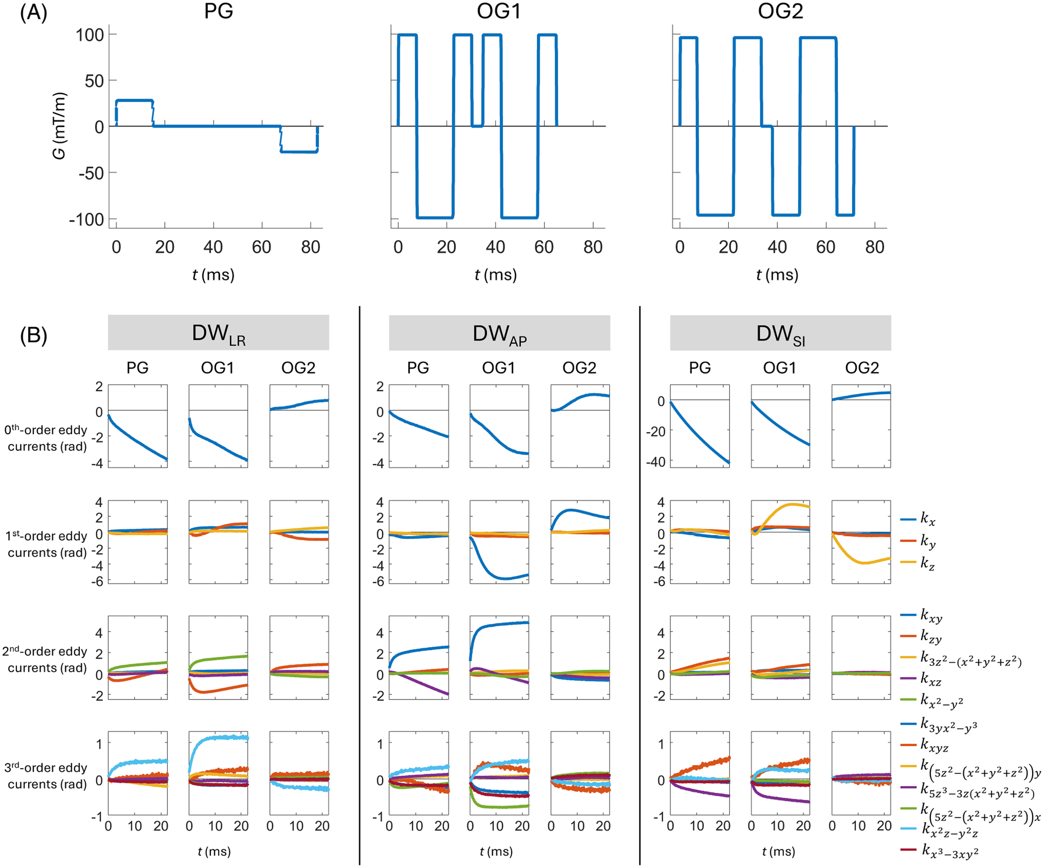
(A) Pulsed (PG), trapezoid-cosine oscillating (OG1 at 33 Hz), and a modified oscillating (OG2 at 35 Hz) diffusion waveforms, and (B) the eddy currents resulting from them for different axes of diffusion encoding measured by a field camera in a 3T high-performance head-only gradient MRI system. In (B), all subplots show the temporally evolving phase accrual (in radians) during a subsequent EPI readout, resulting from the application of diffusion gradients. These evolutions are given in terms of coefficients of spherical harmonic basis functions of different orders (denoted in legend), with scaling that reflects the maximum phase accrual on a sphere of radius 100 mm. The contributions resulting from diffusion encoding were isolated by taking differences between the coefficients of dMRI acquisitions and corresponding acquisitions. Note that vertical scaling is consistent within rows except for the first row (zeroth-order eddy currents), for which the vertical scale is much larger for diffusion encoding along the SI axis than for diffusion encoding along the LR and AP axes. LR: Left-right; AP: Anterior-posterior; SI: Superior-inferior.
Pre-emphasis-based compensation for linear and constant eddy currents, as well as high-order eddy current mitigation,120 are commonly implemented in MRI systems. They are calibrated once at the system installation and upgrad by measuring the eddy current-induced phase error when applying a single trapezoidal gradient. The calibration is protocol-independent. However, the compensation terms depend on both the calibration parameters and the applied gradient waveforms. For example, Xu et al.120 formulated the high-order eddy current compensation terms for PGSE dMRI. For successful clinical translation of OGSE dMRI, a similar formula would need to be provided for OGSE dMRI, implemented, and tested in both clinical and research MRI systems.
In summary, OGSE-induced eddy currents have been shown to introduce different image artifacts in echo-planar acquisitions in different MRI systems.75,117 The varying design of OGSE waveforms may further complicate the behavior and effect of eddy currents. The measurement of phase errors using the field camera will be useful for a comprehensive evaluation of OGSE-induced eddy currents. For correction of image artifacts, corrections of phase errors up to third-order spherical harmonics using the field camera measurement have been shown to achieve good image quality in both echo-planar acquisition117 and spiral acquisition.70 Correction approaches without using the field camera measurement75,117 have also been demonstrated.
2.7 |. Gradient nonlinearity
The actual magnetic gradient field deviates from the ideal value due to the gradient nonlinearity121,122 (Figure 9A), resulting in spatially varying -values and inaccurate estimation of diffusion parameters when unaccounted for.123–125 Errors of 10–20% in diffusion measurements in clinical MRI systems121 and up to 30% in ultra-strong gradient MRI systems126 have been reported. As the small-bore head-only gradient coils target a smaller diameter spherical volume of ≤30 cm for imaging, the gradient nonlinearity is relatively larger in the same-sized sphere compared to whole-body gradient systems. For example, the gradient nonlinearity of head-only gradient systems was reported to range from 6% to 10% in 20-cm diameter spherical volume,67,77 20% in 22 × 22 × 20 cm3 volume,66 and ≤17% in 26-cm diameter spherical volume.64
FIGURE 9.
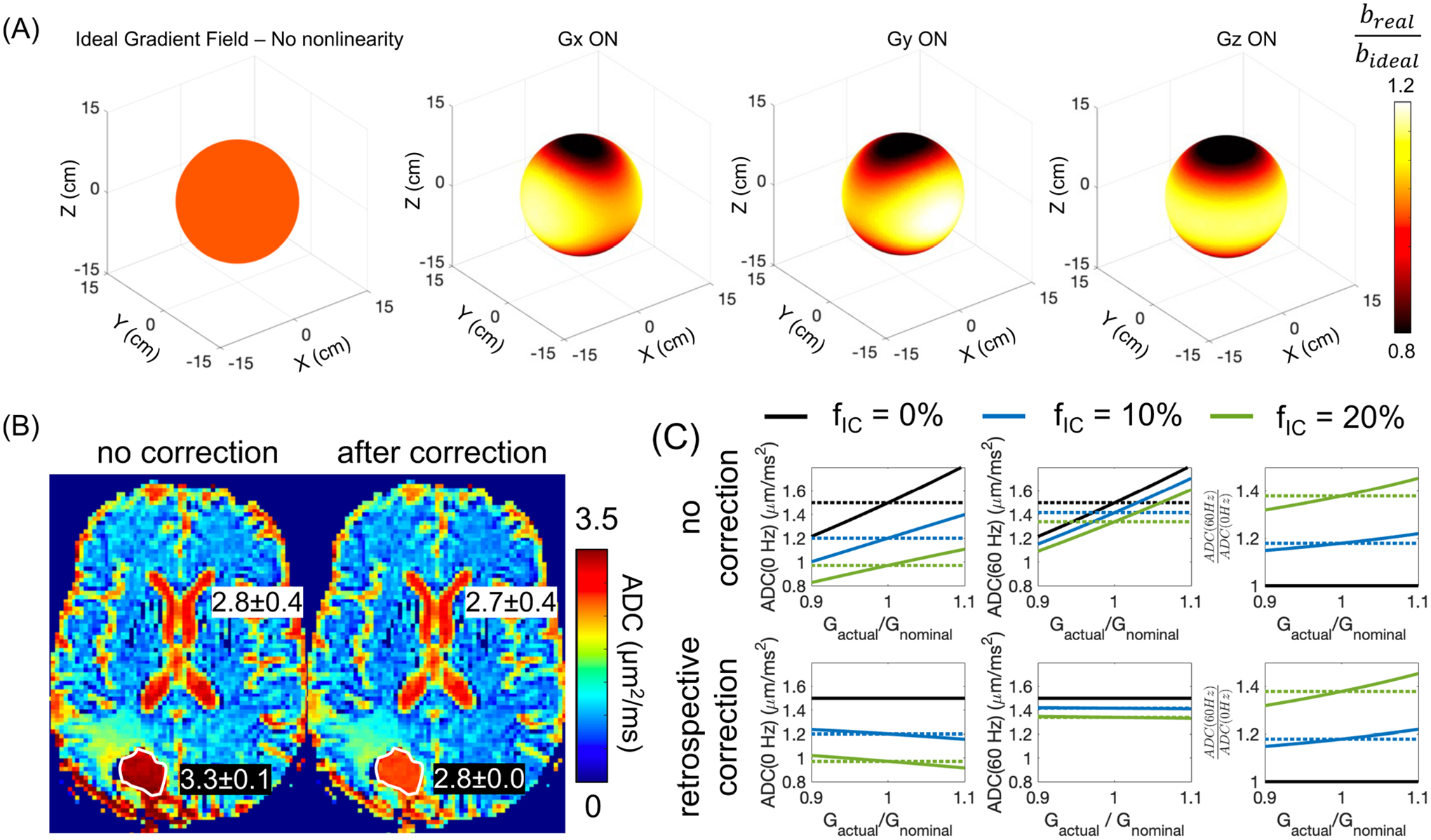
(A) The nonlinear gradient field results in spatially varying -value when the diffusion encoding gradient is played along the physical , and axis, for example, in the 10-cm diameter sphere. (B) ADC is incorrectly estimated without correcting the gradient nonlinearity effect on the -value. For example, in the fluid-filled resected cavity of a glioblastoma patient after surgery, ADC was overestimated, compared to the ADC of the cerebrospinal cord. After correction, the ADC of the fluid-filled resected cavity was close to the ADC of the cerebrospinal cord. (C) Simulation of the effect of gradient nonlinearity on non-Gaussian diffusion measurements, for example, , in a tumor model with a cell radius of 5 μm and different intra-tumoral volume fraction. The retrospective gradient nonlinearity correction largely reduces the bias on ADC(60 Hz) and ADC(0 Hz). However, the bias on cannot be corrected.
In whole-body MRI systems, the effect of gradient nonlinearity along the physical axis can be ameliorated by moving the volume of interest to the iso-center where gradient nonlinearity is neglectable. This approach cannot mitigate the effect when the volume of interest is off-center along X or Y. In head-only systems, the small-bore size of 33–44 cm in diameter prohibits inferior brain regions from being scanned at the iso-center. Therefore, the gradient nonlinearity may have more effect on regions including the cerebellum, brainstem, cervical spine, etc.
In the estimation of diffusion parameters, corrections for nonlinear gradient have been implemented by calculating the actual gradient fields in each voxel and applying them in the diffusion parametric estimation121 (Figure 9B). These methods have been mostly applied and validated in PGSE DWI and DTI, demonstrating improved accuracy and reproducibility of breast DWI123 and brain DTI127 in multicenter studies.
Compared to PGSE DWI and DTI, time-dependent dMRI probes high-order diffusion parameters that reflect the non-Gaussian diffusion process. The effect of gradient nonlinearity on high-order diffusion parameters can also be appreciated in PGSE diffusional kurtosis imaging (DKI). Several studies on both phantom and human brain75,124,128 have shown that DKI parameters have smaller percent errors due to gradient nonlinearity, compared to DTI parameters. Mesri et al.124 showed that the effect of gradient nonlinearity is less prominent at low SNR levels. As DKI is acquired at a high -value and long TE in whole-body MRI systems, the effect of gradient nonlinearity on DKI is overwhelmed by the noise. At a shortened TE and high SNR enabled by the high-performance gradients, the gradient nonlinearity can be problematic for high-order diffusion parameters in both PGSE DKI and OGSE dMRI (Figure 9C). Both the characterization and correction129 are needed to ensure accurate interpretation of tissue microstructure from OGSE dMRI measurements.
In summary, applying OGSE dMRI to probe high-order diffusion parameters is more challenging in regions suffering from high gradient nonlinearity, for example, in the inferior brain scanned in a head-only MRI system, since a high-gradient field is needed for achieving sensitivity to non-Gaussian diffusion. Approaches for correcting gradient nonlinearity effect on non-Gaussian diffusion MRI need further investigation and validation.
2.8 |. Concomitant gradients
When a linear gradient field is generated, it is accompanied by spatially dependent concomitant gradient fields, which are also referred to as Maxwell terms.130,131 The strength of the concomitant gradient field is proportional to the square of the applied linear gradient strength, and inversely proportional to the main magnetic field . Therefore, the effect of concomitant gradient field can be 5–40× higher at high-performance gradient MRI systems (Table 1), compared to clinical whole-body MRI systems. Moreover, asymmetric design of high-performance gradient coils64–69 present both odd and even order concomitant gradient fields,132 whereas the symmetric gradient systems only present even order terms. Therefore, the concomitant gradient effect is much higher in high-performance asymmetric gradient systems. Across different main magnetic fields (Table 1), 7T and 10.5T are less affected by the concomitant gradient field, compared to 3T.
Concomitant gradient fields affect both the gradient-induced image contrast, for example, in dMRI133–135 and phase-contrast MRI,131 and the -space encoding.136 To mitigate the effect of concomitant fields, the 0th and 1st order concomitant field terms can be calibrated and corrected through RF modulation and gradient pre-emphasis.132,137 However, the higher order terms that exist in both symmetric and asymmetric gradient systems, require high-order gradient coils for correction,138 which may not be widely accessible.
In diffusion with asymmetric gradient waveforms on each side of the refocusing pulse, the concomitant gradient has been shown to introduce spatially varying diffusivity measurements.133–135 Since most of the OGSE waveforms used in human studies have a symmetric design, the concomitant gradients are not expected to affect the -space encoding. However, OGSE-induced concomitant gradient fields can cancel the crusher gradient,139 resulting in image artifacts (Supplementary Material S3 and Figure S6). Increased crusher gradient is therefore more important in OGSE dMRI, compared to PGSE dMRI.
2.9 |. Motion and flow
Diffusion-encoding gradients render MR signals sensitive to other forms of motion aside from diffusion, for example, non-rigid motion of organs and perfusion at low -values. This unintentional sensitivity confounds the quantification of ADC if unaccounted for, which may lead to incorrect clinical diagnosis when using DWI and ADC. For example, the non-rigid motion of the liver caused by cardiac motion has been shown to dephase diffusion signals, resulting in overestimation of ADC.134,140 Furthermore, the effect of intravoxel incoherent motion (IVIM),141 that is, microcirculatory flows in the capillary bed, has been observed at low -values in prostate and liver, confounding ADC measurements when it is not modeled. As more clinical OGSE dMRI studies are done in the body, it is important to consider motion-compensation to ensure motion-robust, repeatable time-dependent diffusion measurements.
The effects of non-rigid tissue motion on dMRI can be reduced when the moments of diffusion gradient waveforms are nulled.134,140,142,143 In OGSE, trapezoid-cosine waveforms are most commonly used, which are typically designed to have first-order moments nulled.37,70,144,145 This feature is often achieved by modifying the timing of the quarter-period gradient lobes. Second-order moments of these waveforms can also be nulled.146
The motion compensation of OGSE waveforms is beneficial to many applications where various motions confound diffusion estimates. Jiang et al. used OGSE to perform motion-robust, time-dependent diffusion measurements in the human liver.13 Furthermore, the insensitivity of OGSE to motion-induced phase accumulation benefits OGSE dMRI with multi-shot acquisitions, for which shot-to-shot phase differences corrupt images. Michael et al.146 reported that using oscillating gradients with a high-performance gradient system enabled artifact-free multi-shot diffusion acquisitions in the human brain.
In IVIM, motion-compensated OGSE diffusion encoding also suppresses ballistic flow signals.147 However, another form of IVIM signal—pseudo-diffusive flow—cannot be suppressed by flow-compensated waveform design alone. However, Wu and Zhang148 showed that these signals can be disentangled from OGSE ADC estimates by playing out pulsed gradients orthogonally to oscillating gradients and comparing the signal acquired with pulsed gradients only. This approach is particularly useful when using the low -values () at which the IVIM effect is most pronounced. It can be practically necessary for MRI systems with relatively low gradient strength where high -values () cannot be achieved at high OGSE frequencies.
In summary, the typical motion-compensated nature of OGSE mitigates several forms of errors stemming from non-diffusive motion. Specific OGSE waveform parameterization varies across sites and such compensation must be designed for. When it is performed, robust image quality in body and brain applications can be achieved.
2.10 |. Signal-to-noise ratio
The long diffusion encoding of OGSE waveforms results in long TE≥ 100 ms, and low SNR per acquisition. To boost SNR, large voxel sizes of 20–51 mm3 at 3T,12,51,57–59 10 mm3 at 4.7T,52,61 and 19 mm3 at 7T39 systems have been used in OGSE dMRI acquisitions. These resolutions are relatively low compared to a voxel size of 10 mm3 in clinical DWI at 3T.
Acquisitions strategies have been proposed to improve upon the SNR of standard 2D echo-planar readout in OGSE dMRI. For example, spiral acquisition can reduce TE and increase SNR. In OGSE dMRI, Michael et al.70 reported a TE reduction from 128 ms in echo-planar acquisition to 95 ms in spiral acquisition in a 3T head-only high-performance gradient MRI system. Furthermore, Wu et al.149 applied an oscillating gradient diffusion-prepared 3D gradient spin-echo sequence which has shown an SNR increment of 1.7–2.3 times compared to 2D echo-planar acquisition in a whole-body clinical 3T MRI system. In addition, this 3D acquisition was shown to effectively reduce the duty cycle and reduce the scan time for whole-brain coverage.
Moreover, OGSE waveform designs with shortened duration have been proposed to reduce TE and increase SNR. For example, Borsos et al.145 used a frequency-tuned bipolar oscillating gradient at 7T. The TE at 23 Hz and was reduced to 91 ms, compared to a TE of 128 ms using trapezoid-cosine OGSE at the same frequency and -value. The shortened TE enabled achieving adequate SNR for OGSE-based DKI analysis in the human brain at 75 mT/m.
In summary, SNR is a major challenge to the clinical translation of OGSE dMRI, due to the relatively long TE’s. High-performance gradient MRI shortens the TE and improves SNR. OGSE diffusion encoding with other k-space acquisition approaches, including spiral and 3D gradient spin-echo, as well as the optimized OGSE waveforms, have also been shown to improve SNR.
3 |. DISCUSSION AND CONCLUSIONS
Emerging human high-performance gradient MRI systems undeniably advance dMRI techniques. OGSE dMRI is a technique that greatly benefits from high-performance gradient, enabling the translation from pre-clinical research findings to human research. Effective clinical translation of OGSE dMRI calls for engineering on multiple fronts including MRI system hardware, software calibration and compensation, and pulse sequence design, along with advances in clinical applications.
First, MRI system hardware innovations including high-power gradient driver and power-efficient gradient coils are fundamental to the dissemination of OGSE dMRI in the clinic. Whole-body and head-only MRI systems at remarkably high and are becoming commercially available. The high-performance gradient greatly expands the achievable imaging parameter space of OGSE dMRI of a single image. To enable highly time-efficient acquisition of OGSE dMRI of a 3D volume, power electronic systems need to deliver not only high peak power in a single TR (e.g., ~ 100 ms), but also high average power in the range of seconds to several minutes. Therefore, a highly efficient gradient amplifier is needed to achieve gradient performance without significantly increasing the burden on a site’s power and cooling infrastructure. For example, the use of semiconductor substrates with wider bandgaps in power transistors of the gradient drivers has been shown to have lower power losses,150 allowing higher current and voltage output from the gradient drivers without expensive upgrades of site electrical power infrastructure. Therefore, the developments of power electronics provide a pathway for the drop-in electronic upgrade of existing clinical whole-body MRI systems to high-performance gradient systems, which may enable wide adoption of OGSE dMRI in the clinic.
As the gradient strength and slew rate of MRI system hardware become higher, biophysical safety constraints such as PNS and CS eventually become a bottleneck limiting the usable imaging parameter space of OGSE dMRI in humans. To mitigate such constraints, PNS-optimized gradient coils through electromagnetic field analysis have been conceptualized and produced.89,151 Potential future development of both PNS and CS-optimized large-bore gradient coils, or specialty gradient coils for body anatomies, will further expand the imaging capability of OGSE dMRI. Furthermore, PNS-optimized diffusion encoding waveform design152 may also be useful for improving the imaging parameter space of OGSE dMRI in the existing MRI systems.
Other engineering challenges including eddy current, gradient nonlinearity, concomitant gradient, acoustic noise, and mechanical vibration can also be addressed by either incorporating them in the gradient coil design and/or through modification of other MRI subsystems,110,111 or pulse sequence optimization. With a better understanding of the requirements on individual performance specifications, future development of MRI system hardware and OGSE diffusion encoding waveforms can be accelerated.
In humans, OGSE dMRI has been predominantly studied at 3T, with a few studies demonstrating the feasibility of OGSE dMRI at 7T in human brain.39 Relatively low gradient performance and SNR of 1.5T clinical MRI systems may limit the clinical translation of OGSE dMRI at low fields. However, the advances in gradient coils at low fields and denoising techniques may allow the investigation of OGSE dMRI at low fields in the future. At ultra-high fields, the head-only high-performance gradient coils have been introduced to both 7T67 and 10.5T.68 In these systems, the SNR of OGSE dMRI can benefit from both a short TE and a high main magnetic field. However, the shortening effects at high fields counteract the benefit of high SNR, requiring shorter TE and higher gradient performance for dMRI. In addition, operating high-performance gradient coils at high fields has increased challenges including mechanical stability and motional eddy current. However, the lower concomitant gradient fields at high main magnetic fields benefit dMRI with spiral acquisitions, which shortens TE and boosts SNR. Therefore, continued progress in both hardware engineering and sequence development to address specific challenges at high-field environments will fuel more interest in using advanced dMRI such as OGSE to study the human brain at ultra-high fields.
With high-power efficiency and high PNS and CS thresholds, head-only gradient coil64,66–69 may also accelerate clinical translation of OGSE dMRI for human neuroimaging. These gradient coils not only advance OGSE dMRI in human brain imaging, but also empower other MRI techniques including other advanced dMRI,76 diffusion-relaxation MRI,153–155 functional MRI,156 high-resolution anatomical imaging, and myelin mapping.157 Techniques like these may advance our understanding of brain structure, connectivity, and functions in neurodegenerative diseases, disorders, and brain oncology. Ultimately, they may help meet the need to develop non-invasive radiographic methods and tools in the clinical management of these patients.
Clinical translation of OGSE dMRI necessitates demonstration of its unique value in clinical applications, compared to other MRI techniques that may not require high-performance gradient coils. For example, several OGSE dMRI clinical studies12,55–58,71 have demonstrated improved diagnostic performance in tumor grading and identifying tumor recurrences in oncological applications, compared to clinical DWI and ADC. Chemical exchange saturation transfer (CEST)158 has also shown promise in oncological imaging. Comparing or combining OGSE dMRI with other promising techniques in large studies of tumor patients will be useful for shaping future clinical MRI techniques in oncology. Furthermore, developing new OGSE dMRI-based biomarkers for neurodegenerative disease and disorders that have been validated in animal studies, for example, axonal beading23,25,35,43,52 and demyelination in stroke, may further accelerate clinical adoption of OGSE dMRI.
It is also worth studying the capability of time-dependent DKI versus time-dependent DWI and DTI in characterizing tissue microstructures in clinical studies. Time-dependent DKI with OGSE diffusion encoding has shown unique image contrast that may differentiate restriction cell size and water exchange rate, which may reveal pathological alternations in gray and white matter.54,159 Recent studies have demonstrated the feasibility of OGSE DKI in the human brain.75,145 However, lower maximum frequencies and longer TE were obtained in OGSE DKI at the high (Figures 4–6). In addition, OGSE DKI is accompanied by reduced scan efficiency due to its high power consumption, as well as higher acoustic noise level and mechanical vibration. Improvements in gradient waveform design and MRI system hardware modifications are more critical for the use of OGSE DKI in patient studies.
In summary, growing evidence demonstrates the unique capability of OGSE dMRI in addressing clinically significant problems. We have identified specific engineering challenges facing OGSE dMRI applied to humans. We believe that continued progress in addressing these challenges will ultimately make the clinical adoption of OGSE dMRI feasible soon.
Supplementary Material
ACKNOWLEDGMENTS
We acknowledge funding support by the National Institutes of Health (NIH) under Award Number U01EB034313, P41EB017183, S10OD034309, R01NS095985 and the National Natural Science Foundation of China under Award Number 32427802, U24A200313. The content is solely the responsibility of the authors and does not necessarily represent the official views of the NIH and the National Natural Science Foundation of China.
Dr. Zhu led the manuscript writing. Dr. Michael led the writing of the section on eddy currents, and the section on motion and flow. Dr. Li co-led the writing of the section on concomitant gradient. Dr. Sprenger co-led the writing of the section on gradient driver. Dr. Hua co-led the writing of the section on cardiac stimulation. Dr. Lee, Dr. Yeo, and Dr. McNab contributed to the writing of the Discussion. Dr. Hennel contributed to the writing of the section on eddy current. Dr. Fieremans contributed to the writing of the section on the overview of OGSE methodology. Dr. Wu co-led the writing of the section on acoustic noise and mechanical vibration. Dr. Foo contributed to the writing of the Discussion. Dr. Novikov co-led the writing of the section on the overview of OGSE methodology. All authors contributed to the revision of the manuscript.
The authors thank Dr. Patricia Lan for the discussion on SNR, Mr. John Hotaling, Dr. Rohail Hassan, and Dr. Anil Kumar Reddy Siddavatam for the discussions on the gradient driver system, Mr. Justin Ricci for the discussion on the gradient coil heating, as well as Dr. Sherry Huang for proofreading the manuscript. The authors acknowledge that the patient images in Figure 9 were acquired in collaboration with Dr. Robert Shih, Dr. Kevin DeMarco, and Dr. Vincent Ho at the Walter Reed National Military Medical Center and Uniformed Services University.
Funding information
National Institutes of Health, Grant/Award Numbers: U01EB034313, P41EB017183, S10OD034309, R01NS095985; National Natural Science Foundation of China, Grant/Award Numbers: 32427802, U24A200313
Footnotes
CONFLICT OF INTEREST STATEMENT
Dr. Zhu, Dr. Li, Dr. Sprenger, Dr. Hua, Dr. Lee, Dr. Yeo, and Dr. Foo are employees of GE HealthCare.
SUPPORTING INFORMATION
Additional supporting information may be found in the online version of the article at the publisher’s website.
REFERENCES
- 1.Hanahan D, Weinberg RA. Hallmarks of cancer: The next generation. Cell. 2011;144:646–674. [DOI] [PubMed] [Google Scholar]
- 2.Louis DN, Perry A, Wesseling P, et al. The 2021 WHO classification of tumors of the central nervous system: A summary. Neuro-Oncology. 2021;23:1231–1251. doi: 10.1093/neuonc/noab106 [DOI] [PMC free article] [PubMed] [Google Scholar]
- 3.Senkus E, Kyriakides S, Ohno S, et al. Primary breast cancer: ESMO clinical practice guidelines for diagnosis, treatment and follow-up. Ann Oncol. 2015;26:v8–v30. [DOI] [PubMed] [Google Scholar]
- 4.Leenders GJLH, Kwast TH, Grignon DJ, et al. The 2019 International Society of Urological Pathology (ISUP) consensus conference on grading of prostatic carcinoma. Am J Surg Pathol. 2020;44:e87–e99. [DOI] [PMC free article] [PubMed] [Google Scholar]
- 5.Jiang X, Dudzinski S, Beckermann KE, et al. MRI of tumor T cell infiltration in response to checkpoint inhibitor therapy. J Immunother Cancer. 2020;8:e000328. doi: 10.1136/jitc-2019-000328 [DOI] [PMC free article] [PubMed] [Google Scholar]
- 6.Reynaud O Time-dependent diffusion MRI in cancer: Tissue modeling and applications. Front Phys. 2017;5:1–16. [Google Scholar]
- 7.Reynaud O, Winters KV, Hoang DM, Wadghiri YZ, Novikov DS, Kim SG. Surface-to-volume ratio mapping of tumor microstructure using oscillating gradient diffusion weighted imaging. Magn Reson Med. 2016;76:237–247. [DOI] [PMC free article] [PubMed] [Google Scholar]
- 8.Portnoy S, Fichtner ND, Dziegielewski C, Stanisz MP, Stanisz GJ. In vitro detection of apoptosis using oscillating and pulsed gradient diffusion magnetic resonance imaging. NMR Biomed. 2014;27:371–380. [DOI] [PubMed] [Google Scholar]
- 9.Colvin DC, Loveless ME, Does MD, Yue Z, Yankeelov TE, Gore JC. Earlier detection of tumor treatment response using magnetic resonance diffusion imaging with oscillating gradients. Magn Reson Imaging. 2011;29:315–323. [DOI] [PMC free article] [PubMed] [Google Scholar]
- 10.Reynaud O, Winters KV, Hoang DM, Wadghiri YZ, Novikov DS, Kim SG. Pulsed and oscillating gradient MRI for assessment of cell size and extracellular space (POMACE) in mouse gliomas. NMR Biomed. 2016;29:1350–1363. [DOI] [PMC free article] [PubMed] [Google Scholar]
- 11.Xu J, Jiang X, Devan SP, et al. MRI-cytometry: Mapping nonparametric cell size distributions using diffusion MRI. Magn Reson Med. 2021;85:748–761. [DOI] [PMC free article] [PubMed] [Google Scholar]
- 12.Wu D, Jiang K, Li H, et al. Time-dependent diffusion MRI for quantitative microstructural mapping of prostate cancer. Radiology. 2022;303:578–587. [DOI] [PubMed] [Google Scholar]
- 13.Jiang X, Xu J, Gore JC. Mapping hepatocyte size in vivo using temporal diffusion spectroscopy MRI. Magn Reson Med. 2020;84:2671–2683. [DOI] [PMC free article] [PubMed] [Google Scholar]
- 14.Jiang X, McKinley ET, Xie J, Li H, Xu J, Gore JC. In vivo magnetic resonance imaging of treatment-induced apoptosis. Sci Rep. 2019;9:9540. [DOI] [PMC free article] [PubMed] [Google Scholar]
- 15.Jiang X, Xu J, Gore JC. Quantitative temporal diffusion spectroscopy as an early imaging biomarker of radiation therapeutic response in gliomas: A preclinical proof of concept. Adv Radiat Oncol. 2019;4:367–376. [DOI] [PMC free article] [PubMed] [Google Scholar]
- 16.Brandsma D, Stalpers L, Taal W, Sminia P, van den Bent MJ. Clinical features, mechanisms, and management of pseudoprogression in malignant gliomas. Lancet Oncol. 2008;9:453–461. [DOI] [PubMed] [Google Scholar]
- 17.Matesic DF, Lin RCS. Microtubule-associated protein 2 as an early indicator of ischemia-induced neurodegeneration in the gerbil forebrain. J Neurochem. 1994;63:1012–1020. [DOI] [PubMed] [Google Scholar]
- 18.Murphy TH, Li P, Betts K, Liu R. Two-photon imaging of stroke onset in vivo reveals that NMDA-receptor independent ischemic depolarization is the major cause of rapid reversible damage to dendrites and spines. J Neurosci. 2008;28:1756–1772. [DOI] [PMC free article] [PubMed] [Google Scholar]
- 19.Shepherd GMG, Raastad M, Andersen P. General and variable features of varicosity spacing along unmyelinated axons in the hippocampus and cerebellum. Proc Natl Acad Sci. 2002;99:6340–6345. [DOI] [PMC free article] [PubMed] [Google Scholar]
- 20.Tang-Schomer MD, Johnson VE, Baas PW, Stewart W, Smith DH. Partial interruption of axonal transport due to microtubule breakage accounts for the formation of periodic varicosities after traumatic axonal injury. Exp Neurol. 2012;233:364–372. [DOI] [PMC free article] [PubMed] [Google Scholar]
- 21.Johnson VE, Stewart W, Smith DH. Axonal pathology in traumatic brain injury. Exp Neurol. 2013;246:35–43. [DOI] [PMC free article] [PubMed] [Google Scholar]
- 22.Shapson-Coe A, Januszewski M, Berger DR, et al. A petavoxel fragment of human cerebral cortex reconstructed at nanoscale resolution. Science. 2024;384:eadk4858. doi: 10.1126/science.adk4858 [DOI] [PMC free article] [PubMed] [Google Scholar]
- 23.Abdollahzadeh A, Coronado-Leija R, Lee H-H, Sierra A, Fieremans E, Novikov DS. Scattering approach to diffusion quantifies axonal damage in brain injury arXiv preprint arXiv:2501.18167, 2025. [Google Scholar]
- 24.Lee H-H, Yaros K, Veraart J, et al. Along-axon diameter variation and axonal orientation dispersion revealed with 3D electron microscopy: Implications for quantifying brain white matter microstructure with histology and diffusion MRI. Brain Struct Funct. 2019;224:1469–1488. [DOI] [PMC free article] [PubMed] [Google Scholar]
- 25.Lee H-H, Papaioannou A, Kim S-L, Novikov DS, Fieremans E. A time-dependent diffusion MRI signature of axon caliber variations and beading. Commun Biol. 2020;3:354. [DOI] [PMC free article] [PubMed] [Google Scholar]
- 26.Kiselev VG. Fundamentals of diffusion MRI physics. NMR Biomed. 2017;30:e3602. [DOI] [PubMed] [Google Scholar]
- 27.Jelescu IO, Budde MD. Design and validation of diffusion MRI models of white matter. Front Phys. 2017;5:1–18. [DOI] [PMC free article] [PubMed] [Google Scholar]
- 28.Novikov DS, Fieremans E, Jespersen SN, Kiselev VG. Quantifying brain microstructure with diffusion MRI: Theory and parameter estimation. NMR Biomed. 2019;32:e3998. [DOI] [PMC free article] [PubMed] [Google Scholar]
- 29.Alexander DC, Dyrby TB, Nilsson M, Zhang H. Imaging brain microstructure with diffusion MRI: Practicality and applications. NMR Biomed. 2019;32:e3841. [DOI] [PubMed] [Google Scholar]
- 30.Weiskopf N, Edwards LJ, Helms G, Mohammadi S, Kirilina E. Quantitative magnetic resonance imaging of brain anatomy and in vivo histology. Nat Rev Phys. 2021;3:570–588. [Google Scholar]
- 31.Novikov DS. The present and the future of microstructure MRI: From a paradigm shift to normal science. J Neurosci Methods. 2021;351:108947. [DOI] [PMC free article] [PubMed] [Google Scholar]
- 32.Stejskal EO, Tanner JE. Spin diffusion measurements: Spin echoes in the presence of a time-dependent field gradient. J Chem Phys. 1965;42:288–292. [Google Scholar]
- 33.Gross B, Kosfeld R. Anwendung der spin-echo-methode der messung der selbstdiffusion. Messtechnik. 1969;77:171–177. [Google Scholar]
- 34.Tanner JE. Self diffusion of water in frog muscle. Biophys J. 1979;28:107–116. [DOI] [PMC free article] [PubMed] [Google Scholar]
- 35.Does MD, Parsons EC, Gore JC. Oscillating gradient measurements of water diffusion in normal and globally ischemic rat brain. Magn Reson Med. 2003;49:206–215. [DOI] [PubMed] [Google Scholar]
- 36.Parsons EC Jr, Does MD, Gore JC. Temporal diffusion spectroscopy: Theory and implementation in restricted systems using oscillating gradients. Magn Reson Med. 2006;55:75–84. [DOI] [PubMed] [Google Scholar]
- 37.Van Anh T, Holdsworth SJ, Bammer R. In vivo investigation of restricted diffusion in the human brain with optimized oscillating diffusion gradient encoding. Magn Reson Med. 2014;71:83–94. [DOI] [PMC free article] [PubMed] [Google Scholar]
- 38.Novikov DS, Kiselev VG. Surface-to-volume ratio with oscillating gradients. J Magn Reson. 2011;210:141–145. [DOI] [PubMed] [Google Scholar]
- 39.Arbabi A, Kai J, Khan AR, Baron CA. Diffusion dispersion imaging: Mapping oscillating gradient spin-echo frequency dependence in the human brain. Magn Reson Med. 2020;83:2197–2208. [DOI] [PubMed] [Google Scholar]
- 40.Novikov DS, Kiselev VG. Effective medium theory of a diffusion-weighted signal. NMR Biomed. 2010;23:682–697. [DOI] [PubMed] [Google Scholar]
- 41.Mitra PP, Sen PN, Schwartz LM. Short-time behavior of the diffusion coefficient as a geometrical probe of porous media; 1993. Phys Rev. 1993;B47:8565. [DOI] [PubMed] [Google Scholar]
- 42.Lemberskiy G, Baete SH, Cloos MA, Novikov DS, Fieremans E. Validation of surface-to-volume ratio measurements derived from oscillating gradient spin echo on a clinical scanner using anisotropic fiber phantoms. NMR Biomed. 2017;30:e3708. [DOI] [PMC free article] [PubMed] [Google Scholar]
- 43.Novikov DS, Jensen JH, Helpern JA, Fieremans E. Revealing mesoscopic structural universality with diffusion. Proc Natl Acad Sci. 2014;111:5088–5093. [DOI] [PMC free article] [PubMed] [Google Scholar]
- 44.Burcaw LM, Fieremans E, Novikov DS. Mesoscopic structure of neuronal tracts from time-dependent diffusion. NeuroImage. 2015;114:18–37. [DOI] [PMC free article] [PubMed] [Google Scholar]
- 45.Tan ET, Shih RY, Mitra J, et al. Oscillating diffusion-encoding with a high gradient-amplitude and high slew-rate head-only gradient for human brain imaging. Magn Reson Med. 2020;84:950–965. [DOI] [PMC free article] [PubMed] [Google Scholar]
- 46.Stepišnik J, Lasiè S, Mohorič A, Serša I, Sepe A. Velocity autocorrelation spectra of fluid in porous media measured by the CPMG sequence and constant magnetic field gradient. Magn Reson Imaging. 2007;25:517–520. Proceedings of the Eighth International Bologna Conference on Magnetic Resonance in Porous Media. [DOI] [PubMed] [Google Scholar]
- 47.Jones DK, Alexander DC, Bowtell R, et al. Microstructural imaging of the human brain with a ‘super-scanner’: 10 key advantages of ultra-strong gradients for diffusion MRI. NeuroImage. 2018;182:8–38. doi: 10.1016/j.neuroimage.2018.05.047 [DOI] [PubMed] [Google Scholar]
- 48.Jiang X, Li H, Xie J, et al. In vivo imaging of cancer cell size and cellularity using temporal diffusion spectroscopy. Magn Reson Med. 2017;78:156–164. [DOI] [PMC free article] [PubMed] [Google Scholar]
- 49.Roberts TA, Hyare H, Agliardi G, et al. Noninvasive diffusion magnetic resonance imaging of brain tumour cell size for the early detection of therapeutic response. Sci Rep. 2020;10:9223. doi: 10.1038/s41598-020-65956-4 [DOI] [PMC free article] [PubMed] [Google Scholar]
- 50.Zaccagna F, Riemer F, Priest AN, et al. Non-invasive assessment of glioma microstructure using VERDICT MRI: Correlation with histology. Eur Radiol. 2019;29:5559–5566. [DOI] [PMC free article] [PubMed] [Google Scholar]
- 51.Devan SP, Jiang X, Luo G, et al. Selective cell size MRI differentiates brain tumors from radiation necrosis. Cancer Res. 2022;82:3603–3613. [DOI] [PMC free article] [PubMed] [Google Scholar]
- 52.Baron CA, Kate M, Gioia L, et al. Reduction of diffusion-weighted imaging contrast of acute ischemic stroke at short diffusion times. Stroke. 2015;46:2136–2141. [DOI] [PubMed] [Google Scholar]
- 53.Aggarwal M, Jones MV, Calabresi PA, Mori S, Zhang J. Probing mouse brain microstructure using oscillating gradient diffusion MRI. Magn Reson Med. 2012;67:98–109. [DOI] [PMC free article] [PubMed] [Google Scholar]
- 54.Aggarwal M, Smith MD, Calabresi PA. Diffusion-time dependence of diffusional kurtosis in the mouse brain. Magn Reson Med. 2020;84:1564–1578. [DOI] [PMC free article] [PubMed] [Google Scholar]
- 55.Maekawa T, Hori M, Murata K, et al. Differentiation of high-grade and low-grade intra-axial brain tumors by time-dependent diffusion MRI. Magn Reson Imaging. 2020;72:34–41. [DOI] [PubMed] [Google Scholar]
- 56.Iima M, Yamamoto A, Kataoka M, et al. Time-dependent diffusion MRI to distinguish malignant from benign head and neck tumors. J Magn Reson Imaging. 2019;50:88–95. [DOI] [PubMed] [Google Scholar]
- 57.Kamimura K, Kamimura Y, Nakano T, et al. Differentiating brain metastasis from glioblastoma by time-dependent diffusion MRI. Cancer Imaging. 2023;23:75. doi: 10.1186/s40644-023-00595-2 [DOI] [PMC free article] [PubMed] [Google Scholar]
- 58.Ba R, Wang X, Zhang Z, et al. Diffusion-time dependent diffusion MRI: Effect of diffusion-time on microstructural mapping and prediction of prognostic features in breast cancer. Eur Radiol. 2023;33:6226–6237. [DOI] [PubMed] [Google Scholar]
- 59.Ejima F, Fukukura Y, Kamimura K, et al. Oscillating gradient diffusion-weighted mri for risk stratification of uterine endometrial cancer. J Magn Reson Imaging. 2024;60:67–77. [DOI] [PubMed] [Google Scholar]
- 60.Wu D, Turnbill V, Lee H-H, et al. In vivo mapping of cellular resolution neuropathology in brain ischemia by diffusion MRI bioRxiv 2023 2023.08.08.552374; 2023. doi: 10.1101/2023.08.08.552374 [DOI] [PMC free article] [PubMed] [Google Scholar]
- 61.Tétreault P, Harkins KD, Baron CA, Stobbe R, Does MD, Beaulieu C. Diffusion time dependency along the human corpus callosum and exploration of age and sex differences as assessed by oscillating gradient spin-echo diffusion tensor imaging. NeuroImage. 2020;210:116533. [DOI] [PubMed] [Google Scholar]
- 62.Zhang H, Liu K, Ba R, et al. Histological and molecular classifications of pediatric glioma with time-dependent diffusion MRI-based microstructural mapping. Neuro-Oncology. 2023;25:1146–1156. [DOI] [PMC free article] [PubMed] [Google Scholar]
- 63.Xu J. Probing neural tissues at small scales: Recent progress of oscillating gradient spin echo (OGSE) neuroimaging in humans. J Neurosci Methods. 2021;349:109024. [DOI] [PMC free article] [PubMed] [Google Scholar]
- 64.Foo TKF, Tan ET, Vermilyea ME, et al. Highly efficient head-only magnetic field insert gradient coil for achieving simultaneous high gradient amplitude and slew rate at 3.0T (MAGNUS) for brain microstructure imaging. Magn Reson Med. 2020;83:2356–2369. [DOI] [PubMed] [Google Scholar]
- 65.Huang SY, Witzel T, Keil B, et al. Connectome 2.0: Developing the next-generation ultra-high gradient strength human MRI scanner for bridging studies of the micro-, meso- and macro-connectome. NeuroImage. 2021;243:118530. [DOI] [PMC free article] [PubMed] [Google Scholar]
- 66.Weiger M, Overweg J, Rösler MB, et al. A high-performance gradient insert for rapid and short-T2 imaging at full duty cycle. Magn Reson Med. 2018;79:3256–3266. doi: 10.1002/mrm.26954 [DOI] [PubMed] [Google Scholar]
- 67.Feinberg DA, Beckett AJS, Vu AT, et al. Next-generation MRI scanner designed for ultra-high-resolution human brain imaging at 7 Tesla. Nat Methods. 2023;20:2048–2057. [DOI] [PMC free article] [PubMed] [Google Scholar]
- 68.Rutt B, Bratch A, Alejski A, et al. Design, construction and írst experimental results of the high performance LH7 insertable head gradient set at 10.5 T. ISMRM 2024; 2024. [Google Scholar]
- 69.Wu D, Kang L, Li H, et al. Developing an AI-empowered head-only ultra-high-performance gradient MRI system for high spatiotemporal neuroimaging. NeuroImage. 2024;290:120553. [DOI] [PubMed] [Google Scholar]
- 70.Michael ES, Hennel F, Pruessmann KP. Evaluating diffusion dispersion across an extended range of b-values and frequencies: Exploiting gap-filled OGSE shapes, strong gradients, and spiral readouts. Magn Reson Med. 2022;87:2710–2723. [DOI] [PMC free article] [PubMed] [Google Scholar]
- 71.Zhu A, Shih R, Huang RY, et al. Revealing tumor microstructure with oscillating diffusion encoding MRI in pre-surgical and post-treatment glioma patients. Magn Reson Med. 2023;90:1789–1801. [DOI] [PubMed] [Google Scholar]
- 72.Kakkar LS, Bennett OF, Siow B, et al. Low frequency oscillating gradient spin-echo sequences improve sensitivity to axon diameter: An experimental study in viable nerve tissue. NeuroImage. 2018;182:314–328. Microstructural Imaging. [DOI] [PubMed] [Google Scholar]
- 73.Nilsson M, Lasič S, Drobnjak I, Topgaard D, Westin C-F. Resolution limit of cylinder diameter estimation by diffusion MRI: The impact of gradient waveform and orientation dispersion. NMR Biomed. 2017;30:e3711. [DOI] [PMC free article] [PubMed] [Google Scholar]
- 74.Drobnjak I, Zhang H, Ianuş A, Kaden E, Alexander DC. PGSE, OGSE, and sensitivity to axon diameter in diffusion MRI: Insight from a simulation study. Magn Reson Med. 2016;75:688–700. [DOI] [PMC free article] [PubMed] [Google Scholar]
- 75.Dai E, Zhu A, Yang GK, et al. Frequency-dependent diffusion kurtosis imaging in the human brain using an oscillating gradient spin echo sequence and a high-performance head-only gradient. NeuroImage. 2023;279:120328. [DOI] [PMC free article] [PubMed] [Google Scholar]
- 76.Chakwizira A, Zhu A, Foo T, Westin C-F, Szczepankiewicz F, Nilsson M. Diffusion MRI with free gradient waveforms on a high-performance gradient system: Probing restriction and exchange in the human brain. NeuroImage. 2023;283:120409. [DOI] [PubMed] [Google Scholar]
- 77.Setsompop K, Kimmlingen R, Eberlein E, et al. Pushing the limits of in vivo diffusion MRI for the human connectome project. NeuroImage. 2013;80:220–233. [DOI] [PMC free article] [PubMed] [Google Scholar]
- 78.McNab JA, Edlow BL, Witzel T, et al. The Human Connectome Project and beyond: Initial applications of 300mT/m gradients. NeuroImage. 2013;80:234–245. Mapping the Connectome. [DOI] [PMC free article] [PubMed] [Google Scholar]
- 79.Lee S-K, Bernstein MA. Systematic Dimensional Analysis of the Scaling Relationship for Gradient and Shim Coil Design Parameters. Magn Reson Med. 2022;88:1901–1911. [DOI] [PMC free article] [PubMed] [Google Scholar]
- 80.Scott AD, Kunze KP, Ferreira PF, et al. Leveraging unprecedented ultra-high strength gradients in commercially available MRI for in-vivo diffusion tensor CMR. In Proceedings of the Annual Meeting of ISMRM; 2024 Abstract #0910; 2024. [Google Scholar]
- 81.Dwyer A, Walls A, Gormly K, Raeside M, Withey S. Optimisation and implementation of high b-value DWI using 200 mT/m gradient system for clinical prostate MRI. In Proceedings of the Annual Meeting of ISMRM; 2024 Abstract #4321; 2024. [Google Scholar]
- 82.Merenstein JL, Zhao J, Mullin HA, Rudolph MD, Song AW, Madden DJ. High-resolution multi-shot diffusion imaging of structural networks in healthy neurocognitive aging. NeuroImage. 2023;275:120191. [DOI] [PMC free article] [PubMed] [Google Scholar]
- 83.Cuthbertson JD, Truong T-K, Stormont R, Robb F, Song AW, Darnell D. An iPRES-W coil array for simultaneous imaging and wireless localized shimming of the cervical spinal cord. Magn Reson Med. 2022;88:1002–1014. [DOI] [PMC free article] [PubMed] [Google Scholar]
- 84.Wei Z, Chen Q, Han S, et al. 5T magnetic resonance imaging: Radio frequency hardware and initial brain imaging. Quant Imaging Med Surg. 2023;13:3222–3240. [DOI] [PMC free article] [PubMed] [Google Scholar]
- 85.Zhu A, Tarasek M, Hua Y, et al. Human prostate MRI at ultrahigh-performance gradient: A feasibility study. Magn Reson Med. 2024;91:640–648. [DOI] [PMC free article] [PubMed] [Google Scholar]
- 86.Chronik BA, Rutt BK. Simple linear formulation for magnetostimulation specific to MRI gradient coils. Magn Reson Med. 2001;45:916–919. [DOI] [PubMed] [Google Scholar]
- 87.Lee S-K, Mathieu J-B, Graziani D, et al. Peripheral nerve stimulation characteristics of an asymmetric head-only gradient coil compatible with a high-channel-count receiver array. Magn Reson Med. 2016;76:1939–1950. [DOI] [PMC free article] [PubMed] [Google Scholar]
- 88.Tan ET, Hua Y, Fiveland EW, et al. Peripheral nerve stimulation limits of a high amplitude and slew rate magnetic field gradient coil for neuroimaging. Magn Reson Med. 2020;83: 352–366. [DOI] [PMC free article] [PubMed] [Google Scholar]
- 89.Davids M, Guérin B, Klein V, Wald LL. Optimization of MRI gradient coils with explicit peripheral nerve stimulation constraints. IEEE Trans Med Imaging. 2021;40:129–142. [DOI] [PMC free article] [PubMed] [Google Scholar]
- 90.Davids M, Guérin B, Endt A, Schad LR, Wald LL. Prediction of peripheral nerve stimulation thresholds of MRI gradient coils using coupled electromagnetic and neurodynamic simulations. Magn Reson Med. 2019;81:686–701. [DOI] [PMC free article] [PubMed] [Google Scholar]
- 91.Molendowska M, Fasano F, Rudrapatna U, et al. Physiological effects of human body imaging with 300 mT/m gradients. Magn Reson Med. 2022;87:2512–2520. [DOI] [PMC free article] [PubMed] [Google Scholar]
- 92.Hua Y, Yeo DTB, Foo TKF. Peripheral Nerve Stimulation (PNS) Analysis of MRI Head Gradient Coils with Human Body Models. Springer International Publishing; 2023:39–57. [Google Scholar]
- 93.Klein V, Davids M, Schad LR, Wald LL, Guérin B. Investigating cardiac stimulation limits of MRI gradient coils using electromagnetic and electrophysiological simulations in human and canine body models. Magn Reson Med. 2021;85:1047–1061. [DOI] [PMC free article] [PubMed] [Google Scholar]
- 94.Hua Y, Lee S, Gokyar S, Foo TKF, Yeo DTB. “E-field simulation in human body models for high performance non-whole-body gradient coil IEC cardiac stimulation compliance.” In Proceedings of the Annual Meeting of ISMRM; 2025 Abstract #2578; 2025. [Google Scholar]
- 95.Klein V, Coll-Font J, Vendramini L, et al. Measurement of magnetostimulation thresholds in the porcine heart. Magn Reson Med. 2022;88:2242–2258. [DOI] [PMC free article] [PubMed] [Google Scholar]
- 96.Conturo TE, McKinstry RC, Akbudak E, Robinson BH. Encoding of anisotropic diffusion with tetrahedral gradients: A general mathematical diffusion formalism and experimental results. Magn Reson Med. 1996;35:399–412. [DOI] [PubMed] [Google Scholar]
- 97.Hutter J, Nilsson M, Christiaens D, et al. Highly efficient diffusion MRI by slice-interleaved free-waveform imaging (SIFI); 2018.
- 98.Li K, Wu G, Printz E, Kanda K, Wiza MA. System and method for performing magnetic resonance diffusion weighted imaging of an object; 2018.
- 99.Szczepankiewicz F, Westin C-F, Nilsson M. Gradient waveform design for tensor-valued encoding in diffusion MRI. J Neurosci Methods. 2021;348:109007. [DOI] [PMC free article] [PubMed] [Google Scholar]
- 100.Hiltunen J, Hari R, Jousmäki V, Müller K, Sepponen R, Joensuu R. Quantification of mechanical vibration during diffusion tensor imaging at 3 T. NeuroImage. 2006;32:93–103. [DOI] [PubMed] [Google Scholar]
- 101.Gallichan D, Scholz J, Bartsch A, Behrens TE, Robson MD, Miller KL. Addressing a systematic vibration artifact in diffusion-weighted MRI. Hum Brain Mapp. 2010;31:193–202. [DOI] [PMC free article] [PubMed] [Google Scholar]
- 102.Berl MM, Walker L, Modi P, et al. Investigation of vibration-induced artifact in clinical diffusion-weighted imaging of pediatric subjects. Hum Brain Mapp. 2015;36:4745–4757. [DOI] [PMC free article] [PubMed] [Google Scholar]
- 103.Weidlich D, Zamskiy M, Maeder M, Ruschke S, Marburg S, Karampinos DC. Reduction of vibration-induced signal loss by matching mechanical vibrational states: Application in high b-value diffusion-weighted MRS. Magn Reson Med. 2020;84:39–51. [DOI] [PubMed] [Google Scholar]
- 104.Davies-Jenkins CW, Döring A, Fasano F, et al. Practical considerations of diffusion-weighted MRS with ultra-strong diffusion gradients. Front Neurosci. 2023;17:17. [DOI] [PMC free article] [PubMed] [Google Scholar]
- 105.Chen X, Kang L, Zhu Q, Hsu Y-C, Wu D. Acoustic noise optimization of trapezoid oscillating diffusion encoding gradient; 2024.
- 106.Wu J, Kang T, Lan X, et al. IMPULSED model based cytological feature estimation with U-Net: Application to human brain tumor at 3T. Magn Reson Med. 2023;89:411–422. [DOI] [PubMed] [Google Scholar]
- 107.Xu J, Li K, Smith RA, et al. Characterizing tumor response to chemotherapy at various length scales using temporal diffusion spectroscopy. PLoS One. 2012;7:1–8. [DOI] [PMC free article] [PubMed] [Google Scholar]
- 108.IEC (International Electrotechnical Commission). Particular requirements for the basic safety and essential performance of magnetic resonance equipment for medical diagnosis. Geneva: IEC;60601–2-33; 2022. [Google Scholar]
- 109.Safety, Occupational, (OSHA)., Health Administration. Occupational noise exposure. 29 C.F.R; 1988;1910.95.
- 110.Boulant N, Ma S, Walker E, et al. Acoustic noise reduction in the NexGen 7T scanner. Magn Reson Med. 2024;92:2261–2270. [DOI] [PMC free article] [PubMed] [Google Scholar]
- 111.Lee SK, Tarasek MR, Park K, Yeo DTB, Foo TKF. Insertable, dual-density dielectric barrier for acoustic pressure level reduction in a high-performance human head-only MRI system. Magn Reson Imaging. 2024;114:110224. [DOI] [PubMed] [Google Scholar]
- 112.Jezzard P, Barnett AS, Pierpaoli C. Characterization of and correction for eddy current artifacts in echo planar diffusion imaging. Magn Reson Med. 1998;39:801–812. [DOI] [PubMed] [Google Scholar]
- 113.Alexander AL, Tsuruda JS, Parker DL. Elimination of eddy current artifacts in diffusion-weighted echo-planar images: The use of bipolar gradients. Magn Reson Med. 1997;38:1016–1021. [DOI] [PubMed] [Google Scholar]
- 114.Reese TG, Heid O, Weisskoff RM, Wedeen VJ. Reduction of eddy-current-induced distortion in diffusion MRI using a twice-refocused spin echo. Magn Reson Med. 2003;49:177–182. [DOI] [PubMed] [Google Scholar]
- 115.Andersson JLR, Sotiropoulos SN. An integrated approach to correction for off-resonance effects and subject movement in diffusion MR imaging. NeuroImage. 2016;125:1063–1078. [DOI] [PMC free article] [PubMed] [Google Scholar]
- 116.Wilm BJ, Nagy Z, Barmet C, et al. Diffusion MRI with concurrent magnetic field monitoring. Magn Reson Med. 2015;74:925–933. [DOI] [PubMed] [Google Scholar]
- 117.Valsamis JJ, Dubovan PI, Baron CA. Characterization and correction of time-varying eddy currents for diffusion MRI. Magn Reson Med. 2022;87:2209–2223. [DOI] [PubMed] [Google Scholar]
- 118.Ma R, Akçakaya M, Moeller S, et al. A field-monitoring-based approach for correcting eddy-current-induced artifacts of up to the 2nd spatial order in human-connectome-project-style multiband diffusion MRI experiment at 7T: A pilot study. NeuroImage. 2020;216:116861. [DOI] [PMC free article] [PubMed] [Google Scholar]
- 119.Hennel F, Michael ES, Pruessmann KP. Improved gradient waveforms for oscillating gradient spin-echo (OGSE) diffusion tensor imaging. NMR Biomed. 2021;34:e4434 e4434 NBM-20–0139.R1. [DOI] [PubMed] [Google Scholar]
- 120.Xu D, Maier JK, King KF, et al. Prospective and retrospective high order eddy current mitigation for diffusion weighted echo planar imaging. Magn Reson Med. 2013;70:1293–1305. [DOI] [PubMed] [Google Scholar]
- 121.Tan ET, Marinelli L, Slavens ZW, King KF, Hardy CJ. Improved correction for gradient nonlinearity effects in diffusion-weighted imaging. J Magn Reson Imaging. 2013;38:448–453. [DOI] [PubMed] [Google Scholar]
- 122.Barnett AS, Irfanoglu MO, Landman B, Rogers B, Pierpaoli C. Mapping gradient nonlinearity and miscalibration using diffusion-weighted MR images of a uniform isotropic phantom. Magn Reson Med. 2021;86:3259–3273. [DOI] [PMC free article] [PubMed] [Google Scholar]
- 123.Malyarenko DI, Newitt DC, Amouzandeh G, et al. Retrospective correction of ADC for gradient nonlinearity errors in multicenter breast DWI trials: ACRIN6698 multiplatform feasibility study. Tomography. 2020;6:86–92. [DOI] [PMC free article] [PubMed] [Google Scholar]
- 124.Mesri HY, David S, Viergever MA, Leemans A. The adverse effect of gradient nonlinearities on diffusion MRI: From voxels to group studies. NeuroImage. 2020;205:116127. [DOI] [PubMed] [Google Scholar]
- 125.Guo F, Luca A, Parker G, et al. The effect of gradient nonlinearities on fiber orientation estimates from spherical deconvolution of diffusion magnetic resonance imaging data. Hum Brain Mapp. 2021;42:367–383. doi: 10.1002/hbm.25228 [DOI] [PMC free article] [PubMed] [Google Scholar]
- 126.Rudrapatna U, Parker GD, Roberts J, Jones DK. A comparative study of gradient nonlinearity correction strategies for processing diffusion data obtained with ultra-strong gradient MRI scanners. Magn Reson Med. 2021;85:1104–1113. [DOI] [PMC free article] [PubMed] [Google Scholar]
- 127.Hansen CB, Rogers BP, Schilling KG, et al. Empirical field mapping for gradient nonlinearity correction of multi-site diffusion weighted MRI. Magn Reson Imaging. 2021;76:69–78. [DOI] [PMC free article] [PubMed] [Google Scholar]
- 128.Malyarenko DI, Chenevert TL. Practical correction of gradient nonlinearity bias for mean diffusion kurtosis model parameters. no. 4353ISMRM 20202; 2020.
- 129.Zhu A, Lee S-K, Malyarenko DI, Chenevert TL, Swanson S, Bernstein MA. Prospective gradient nonlinearity correction for diffusion MRI: Uncover lost sensitivity to non-Gaussian diffusion and tissue microstructure. no. 2413ISMRM 2024; 2024.
- 130.Norris DG, Hutchison JMS. Concomitant magnetic field gradients and their effects on imaging at low magnetic field strengths. Magn Reson Imaging. 1990;8:33–37. [DOI] [PubMed] [Google Scholar]
- 131.Bernstein MA, Zhou XJ, Polzin JA, et al. Concomitant gradient terms in phase contrast MR: Analysis and correction. Magn Reson Med. 1998;39:300–308. [DOI] [PubMed] [Google Scholar]
- 132.Tao S, Weavers PT, Trzasko JD, et al. Gradient pre-emphasis to counteract first-order concomitant fields on asymmetric MRI gradient systems. Magn Reson Med. 2017;77:2250–2262. [DOI] [PMC free article] [PubMed] [Google Scholar]
- 133.Baron CA, Lebel RM, Wilman AH, Beaulieu C. The effect of concomitant gradient fields on diffusion tensor imaging. Magn Reson Med. 2012;68:1190–1201. [DOI] [PubMed] [Google Scholar]
- 134.Peña-Nogales Ó, Zhang Y, Wang X, et al. Optimized Diffusion-Weighting Gradient Waveform Design (ODGD) formulation for motion compensation and concomitant gradient nulling. Magn Reson Med. 2019;81:989–1003. [DOI] [PMC free article] [PubMed] [Google Scholar]
- 135.Szczepankiewicz F, Westin C-F, Nilsson M. Maxwell-compensated design of asymmetric gradient waveforms for tensor-valued diffusion encoding. Magn Reson Med. 2019;82:1424–1437. [DOI] [PMC free article] [PubMed] [Google Scholar]
- 136.King KF, Ganin A, Zhou XJ, Bernstein MA. Concomitant gradient field effects in spiral scans. Magn Reson Med. 1999;41:103–112. [DOI] [PubMed] [Google Scholar]
- 137.Abad N, Lee S-K, Ajala A, et al. Calibration of concomitant field offsets using phase contrast MRI for asymmetric gradient coils. Magn Reson Med. 2023;89:262–275. [DOI] [PMC free article] [PubMed] [Google Scholar]
- 138.Lee S-K, Ajala A, Foo TK-F. Systems and methods of correcting effects of second-order concomitant fields in a magnetic resonance system with a second-order correction coil assembly; 2024. [DOI] [PubMed]
- 139.Bernstein MA, King KF, Zhou XJ. Handbook of MRI Pulse Sequence. Elsevier; 2004. [Google Scholar]
- 140.Aliotta E, Wu HH, Ennis DB. Convex optimized diffusion encoding (CODE) gradient waveforms for minimum echo time and bulk motion–compensated diffusion-weighted MRI. Magn Reson Med. 2017;77:717–729. [DOI] [PubMed] [Google Scholar]
- 141.Le Bihan D, Breton E, Lallemand D, Aubin ML, Vignaud J, Laval-Jeantet M. Separation of diffusion and perfusion in intravoxel incoherent motion MR imaging. Radiology. 1988;168:497–505. [DOI] [PubMed] [Google Scholar]
- 142.Szczepankiewicz F, Sjölund J, Dall’Armellina E, et al. Motion-compensated gradient waveforms for tensor-valued diffusion encoding by constrained numerical optimization. Magn Reson Med. 2021;85:2117–2126. doi: 10.1002/mrm.28551 [DOI] [PMC free article] [PubMed] [Google Scholar]
- 143.Nguyen CT, Christodoulou AG, Coll-Font J, et al. Free-breathing diffusion tensor MRI of the whole left ventricle using second-order motion compensation and multitasking respiratory motion correction. Magn Reson Med. 2021;85:2634–2648. [DOI] [PMC free article] [PubMed] [Google Scholar]
- 144.Baron CA, Beaulieu C. Oscillating gradient spin-echo (OGSE) diffusion tensor imaging of the human brain. Magn Reson Med. 2014;72:726–736. [DOI] [PubMed] [Google Scholar]
- 145.Borsos KB, Tse DHY, Dubovan PI, Baron CA. Tuned bipolar oscillating gradients for mapping frequency dispersion of diffusion kurtosis in the human brain. Magn Reson Med. 2023;89:756–766. [DOI] [PubMed] [Google Scholar]
- 146.Michael ES, Hennel F, Pruessmann KP. Multi-shot diffusion MRI of the human brain with motion-compensated oscillating gradients. no. 1324ISMRM 2021; 2021.
- 147.Ahlgren A, Knutsson L, Wirestam R, et al. Quantification of microcirculatory parameters by joint analysis of flow-compensated and non-flow-compensated intravoxel incoherent motion (IVIM) data. NMR Biomed. 2016;29:640–649. [DOI] [PMC free article] [PubMed] [Google Scholar]
- 148.Wu D, Zhang J. the effect of microcirculatory flow on oscillating gradient diffusion MRI and Diffusion Encoding with Dual-Frequency Orthogonal Gradients (DEFOG). Magn Reson Med. 2017;77:1583–1592. [DOI] [PMC free article] [PubMed] [Google Scholar]
- 149.Wu D, Liu D, Hsu Y-C, et al. Diffusion-prepared 3D gradient spin-echo sequence for improved oscillating gradient diffusion MRI. Magn Reson Med. 2021;85:78–88. [DOI] [PubMed] [Google Scholar]
- 150.Wang R, Sabate J, Kanakasabai V, Singh Y, Ganesh J, Hu H. Advanced gradient driver design with silicon carbide MOSFETs. In Proceedings of the Annual Meeting of ISMRM; 2018 Abstract #0950; 2018. [Google Scholar]
- 151.Davids M, Vendramini L, Klein V, Ferris N, Guerin B, Wald LL. Experimental validation of a PNS-optimized whole-body gradient coil. Magn Reson Med. 2024;92:1788–1803. [DOI] [PMC free article] [PubMed] [Google Scholar]
- 152.Hannum A, Loecher M, Setsompop K, Ennis D. Mitigating peripheral nerve stimulation in cardiac diffusion tensor imaging (cDTI) with time-optimal diffusion encoding gradient waveform design. J Cardiovasc Magn Reson. 2024;26:100924. doi: 10.1016/j.jocmr.2024.100924 [DOI] [Google Scholar]
- 153.Veraart J, Novikov DS, Fieremans E. TE dependent Diffusion Imaging (TEdDI) distinguishes between compartmental T2 relaxation times. NeuroImage. 2018;182:360–369. [DOI] [PMC free article] [PubMed] [Google Scholar]
- 154.Gong T, Tong Q, He H, Sun Y, Zhong J, Zhang H. MTE-NODDI: Multi-TE NODDI for disentangling non-T2-weighted signal fractions from compartment-specific T2 relaxation times. NeuroImage. 2020;217:116906. [DOI] [PubMed] [Google Scholar]
- 155.Tax CMW, Kleban E, Chamberland M, Barakovič M, Rudrapatna U, Jones DK. Measuring compartmental T2-orientational dependence in human brain white matter using a tiltable RF coil and diffusion-T2 correlation MRI. NeuroImage. 2021;236:117967. [DOI] [PMC free article] [PubMed] [Google Scholar]
- 156.Kang D, In M-H, Jo HJ, et al. Improved resting-state functional MRI using multi-echo echo-planar imaging on a compact 3T MRI scanner with high-performance gradients. Sensors. 2023;23:1–19. [DOI] [PMC free article] [PubMed] [Google Scholar]
- 157.Baadsvik EL, Weiger M, Froidevaux R, Schildknecht CM, Ineichen BV, Pruessmann KP. Myelin bilayer mapping in the human brain in vivo. Magn Reson Med. 2024;91:2332–2344. [DOI] [PubMed] [Google Scholar]
- 158.Jones KM, Pollard AC, Pagel MD. Clinical applications of chemical exchange saturation transfer (CEST) MRI. J Magn Reson Imaging. 2018;47:11–27. [DOI] [PMC free article] [PubMed] [Google Scholar]
- 159.Wu D, Li Q, Northington FJ, Zhang J. Oscillating gradient diffusion kurtosis imaging of normal and injured mouse brains. NMR Biomed. 2018;31:e3917. [DOI] [PMC free article] [PubMed] [Google Scholar]
Associated Data
This section collects any data citations, data availability statements, or supplementary materials included in this article.