

Abstract
Passive radar (PR) relies on receiving signals reflected from targets by other existing noncooperative radiation sources, which are broadly divided into ground- and space-based categories, to achieve target detection and tracking. In the context of space-based PR, this paper proposes a PR using the Iridium satellite signal, which is a low-orbit satellite communication signal with global coverage. With an improved detection range and accredited ambiguity function, a PR using the Iridium satellite signal can address the issues of limited terrestrial coverage for ground-based PR and insufficient receiving power for medium- to high-orbit space-based PR. In addition, to address the problem of multipath clutter broadening caused by the dual movement of low-orbit satellites and the PR receiver, this paper proposes a nonuniform Doppler extraction-enhanced multichannel extensive cancellation algorithm (NuDE-mECA) to suppress multipath clutter broadening while preserving near-field low-speed target detection capabilities. Compared with the traditional multichannel ECA and uniform Doppler extraction multichannel ECA, the NuDE-mECA achieves significantly reduced computational complexity while improving clutter suppression performance and maintaining detection capabilities for low-speed targets. These results provide valuable insights for the lightweight and high-precision design of space-based PR systems.
Keywords: Passive radar, Iridium satellite signal, Detection power analysis, Multichannel extensive cancellation algorithm
Subject terms: Engineering, Electrical and electronic engineering
Introduction
Active radar has strong autonomy and high accuracy in target detection, but its successful operation is vulnerable to threats. As shown in Fig. 1, PR1–4 uses electromagnetic signals emitted by third-party noncooperative radiation sources to illuminate targets, passively receiving scattered signals from targets to obtain information such as target orientation and velocity. The system has separate transmitting and receiving stations, and the receiving station works passively, which not only saves spectrum resources but also minimizes mechanical wear.
Fig. 1.

Scenario diagram of the PR.
Macroscopically, the external radiation source signals that PR can utilize can be divided into two categories: ground-based and space-based. Compared with ground-based PR, space-based PR can effectively solve the problem of insufficient coverage of ground-based PR. At present, research on space-based PR has focused mainly on mature medium- to high-order satellites, such as the Global Navigation Satellite System (GNSS)5–10, DVB-S/S2/S2X11–13, and INMARSAT14–16. Owing to issues such as high signal orbit, insufficient landing power, suppression of various clutter and interference in medium- and high-orbit satellites, target detection is difficult. In contrast, low-orbit satellite PR has advantages such as low orbit, low path loss, strong received power, many satellites, and a stable signal source. Since 2015, large-scale deployment and application research on the low Earth orbit (LEO) satellite internet has been conducted worldwide. Among them, Iridium can provide stable external radiation source signals with global all-weather and time-domain coverage, which can provide considerable detection distance and accuracy for passive target detection. Therefore, using the Iridium satellite signal as an external radiation source and conducting related research has important practical value.
Owing to the diffuse reflection of radiation source signals by various stationary or nonstationary objects, various clutter and interference signals exist in the received echo signals. Therefore, clutter suppression technology is crucial for studying the external radiation source radar system of Iridium satellites. The commonly used clutter suppression techniques for traditional radar include moving target indication (MTI) and moving target detection (MTD). For PR, because the target echo is the signal scattered back by a third-party noncooperative radiation source after being irradiated on the target, the intensity is much lower than that of multipath clutter, and the target is masked by the sidelobes of clutter. Therefore, neither of the above two techniques is applicable to PR. At present, the processing of clutter can be divided into three categories: spatial domain, frequency domain, and time domain methods. If spatial or frequency domain clutter suppression methods are used, further processing of persistent clutter in the time domain will ultimately be needed. Therefore, this paper studies time-domain adaptive clutter suppression algorithms.
The essence of adaptive clutter suppression is a constrained optimization problem, which solves the optimal value of the performance function based on the best criteria. The commonly used best criteria include the MMSE criterion, maximum likelihood (ML) criterion, and least squares (LS) criterion. Adaptive clutter suppression algorithms can be divided into iterative algorithms and noniterative algorithms. Iterative algorithms include the LMS algorithm, NLMS algorithm, and RLS algorithm17. Noniterative algorithms include the extensive cancellation algorithm (ECA) and ECA batch (ECA-B) algorithm. The ECA algorithm was proposed by Colone et al.18. Its principle is to project the signal onto a subspace orthogonal to the clutter to filter out zero-frequency multipath clutter. Owing to the weak adaptability of the algorithm with fixed filtering coefficients in time-varying multipath clutter environments and the high computational complexity of the LS algorithm involving complex matrix operations, many researchers have proposed corresponding improved algorithms to address the above issues.
In 2009, Colone et al.19 proposed the ECA-B to further reduce computational complexity. The core of this algorithm is to divide the signal into subbands and process them in batches while also improving the adaptability of the algorithm. In 2012, Zhao et al.20 utilized the modulation characteristics of orthogonal frequency division multiplexing (OFDM) signals, namely, the correlation between direct waves and multipath clutter of the same carrier in the signal, to project individual carriers one by one into subspaces orthogonal to the clutter subspace carriers, thereby achieving the goal of reducing computational complexity. However, batch processing can cause changes in the Doppler resolution of the signal, leading to low Doppler targets being mistaken for clutter and suppressed. In 2016, Colone et al.21 proposed ECA sliding (ECA-S) after ECA-B. Compared with the block mechanism, the sliding window mechanism can estimate the filter coefficients more smoothly. In the same year, Liu Yu et al.22 proposed the frequency-domain ECA-B algorithm for large-signal-bandwidth scenarios. This method aims to utilize the groove broadening characteristic in the Doppler dimension and apply it to the distance dimension through frequency domain changes, thereby reducing computational complexity. In 2017, Chen Wei et al.23 studied the performance improvement effect of a graphics processing unit (GPU) on related algorithms when studying clutter suppression of external radiation source radar. They combined the ECA-B algorithm with a GPU to further shorten the computation time and verified the efficiency of the method using measured data. Zhao et al.24 proposed an extended algorithm for carrier domain ECA based on DRM passive radiation source radar, which improved the clutter cancellation performance of the system. In 2020, Schupbach et al.25 compared the performance of various suppression algorithms in terms of detection performance and processing time and proposed the ECA-CD algorithm based on the characteristics of OFDM signals, which improved the computational efficiency of the algorithm. In 2021, Lyu et al.26 rederived the ECA algorithm from the perspective of maximum likelihood (ML) and improved the estimation process of weight values, making the derivation process simpler and improving computational efficiency. In 2023, Zhao et al.27 proposed a parallel signal processing scheme that uses high-performance GPUs as hardware platforms and CUDA as software platforms to optimize the ECA-B, range Doppler, and constant false alarm detection algorithms. Zhao28 proposed a frequency-domain processing-based external radiation source radar clutter cancellation method that directly estimates the position and amplitude of multipath clutter based on frequency-domain processing and then uses the estimated parameters to eliminate multipath clutter directly. This algorithm can be combined with the ECA algorithm to directly construct the ECA cancellation matrix using the estimated multipath clutter positions, which can effectively reduce the computational complexity of the ECA algorithm. In 2024, Sui et al.29 proposed ECA-OS, which can suppress fractional-order Doppler clutter and fractional-order distance clutter under low-computational-complexity conditions. Jia et al.30 proposed an ECA-B algorithm based on LDLT decomposition, and the experimental results revealed that, compared with traditional algorithms, the proposed algorithm has greater timeliness and effectiveness.
In summary, the time-domain adaptive filtering algorithm is simple to implement, but there is a contradiction between convergence speed, convergence stability, and computational complexity. The ECA algorithm has excellent clutter suppression ability and does not have convergence problems, but it requires many matrix operations and high computational complexity.
This paper proposes the use of the Iridium satellite ITL signal as an opportunity source and studies the detection power and resolution characteristics based on PR using the Iridium satellite signal. The suppression performance of commonly used time-domain adaptive clutter suppression algorithms was studied for the direct wave and multipath clutter suppression problem at the receiving end of PR using Iridium satellite signal systems. A clutter Doppler broadening monitoring channel model was constructed for clutter Doppler broadening scenarios, and a nonuniform Doppler extraction-enhanced multichannel extensive cancellation algorithm (NuDE-mECA) was proposed. The previous ECA-B algorithm processes signals in multiple batches, which can reduce computational complexity to a certain extent and obtain wider Doppler notches. However, it struggles to effectively handle clutter Doppler broadening and exhibits insufficient capability in detecting near-field low-speed targets. Although the ECA-CD algorithm is computationally efficient and suitable for OFDM signals, its performance is limited when dealing with nonuniform Doppler-broadened clutter. In contrast, the NuDE-mECA algorithm proposed in this paper introduces a two-stage nonuniform Doppler extraction technique based on the multichannel extensive cancellation algorithm, performing differentiated suppression on strong and weak clutter. It significantly reduces computational complexity, improves clutter suppression performance, maintains the detection capability for near-field low-speed targets, and is more suitable for scenarios with clutter Doppler broadening caused by the dual movement of low-orbit satellites and receivers.
Detection performance of the PR using the Iridium satellite signal
System model
To analyze its detection performance and establish a receiver signal model for subsequent analysis, Fig. 2 shows the PR signal processing flowchart based on the Iridium satellite signal. The system receives direct wave signals and echo signals through reference channels and echo channels. After a series of processes, including preprocessing, interference suppression, coherent accumulation, and signal detection, it achieves target localization and tracking.
Fig. 2.

Flowchart of Iridium PR signal processing.
Analysis of the maximum detection distance
The first-generation Iridium satellite system was proposed in the late 1980s31 and officially declared bankrupt in March 2000. Iridium II is a second-generation system built based on the first-generation Iridium system. It was officially launched in 2007 and completed in 2019 and has now been commercialized. The Iridium mentioned in this paper refers to Iridium II. The Iridium constellation is in polar orbit and has global coverage capability. The ITL signal data segment of the Iridium satellite is modulated in a truncated pseudorandom sequence, effectively reducing the information transmission rate while enhancing the signal penetration capability, which is suitable for long-distance detection.
This section demonstrates the feasibility and advantages of PR via the Iridium satellite signal by analyzing and comparing the detection power of the Iridium signal, Starlink signal, GPS signal, and DVB-S signal. Table 1 lists the meanings of the symbols used in this section, and Table 2 lists the link parameters of each satellite signal PR system. The opportunity source parameters refer to reference32, and the receiver parameter settings refer to reference33.
Table 1.
Symbol definitions.
| Parameter | Meaning |
|---|---|
 |
Satellite landing power |
 |
Satellite signal transmission power |
 |
Satellite antenna directional gain |
 |
The height of the satellite from the ground |
 |
Transmission loss |
 |
Equivalent Isotropic Radiated Power of satellite |
 |
Equivalent area of receiving antenna |
 |
Satellite signal carrier wavelength |
 |
Receiving antenna gain |
 |
Direct wave signal power |
 |
Coherent processing gain |
 |
Receiver noise power |
 |
Boltzmann constant |
 |
Receiver noise temperature |
 |
Receiver bandwidth |
 |
Receiver noise figure |
 |
Direct wave signal-to-noise ratio |
 |
Carrier Frequency |
 |
Power density of target echo signal |
 |
Distance from target to receiving antenna |
Table 2.
Link budget parameters of the PR using satellite signals.
| Parameter | Iridium II | Starlink | GPS | DVB-S | |
|---|---|---|---|---|---|
| Opportunity source |  |
28 | 22 | 24 | 51.7 |
 |
780 | 330 | 20,200 | 36,000 | |
 |
1.626 | 11.7 | 1.56 | 12 | |
| Receive system |  |
25 | 30 | 25 | 30 |
 |
1.38 × 10⁻²³ | 1.38 × 10⁻²³ | 1.38 × 10⁻²³ | 1.38 × 10⁻²³ | |
 |
290 | 290 | 290 | 290 | |
 |
0.0315 | 250 | 10.23 | 36 | |
 |
3 | 3 | 3 | 3 | |
 |
5 | 5 | 5 | 5 | |
 |
0 ~ 2 | 0 ~ 2 | 0 ~ 2 | 0 ~ 2 | |
 |
8.2 | 8.2 | 8.2 | 8.2 | |
| Target |  |
10/50/100 | 10/50/100 | 10/50/100 | 10/50/100 |
The direct wave power is directly related to the effectiveness of reference signal purification and clutter suppression and is a prerequisite for subsequent signal processing. According to reference33, the power of the direct wave signal is
 |
1 |
Table 3 shows the direct wave power of the Iridium signal, Starlink signal, GPS signal, and DVB-S signal without considering transmission loss and coherent processing gain. Compared with the Starlink signal, GPS signal, and DVB-S signal, the Iridium signal has the advantages of low propagation loss and high output power as an opportunity source.
Table 3.
SNR of the PR direct wave using satellite signals.
| Direct wave power | Iridium | Starlink | GPS | DVB − S |
|---|---|---|---|---|
 |
− 76.5 | − 87.2 | − 108.4 | − 98.5 |
According to the equation of the dual-base radar, the Equation for the maximum detection distance can be obtained:
 |
2 |
Figure 3 shows the variation curves of the detection distance with the coherent processing time for the Iridium signal, Starlink signal, GPS signal, and DVB-S signal under different target RCS values under ideal conditions. As shown in Fig. 3, the longer the accumulation time is, the greater the detection distance, but the maximum detection distance does not exceed the coverage range of the beam. Iridium has a detection capability one order of magnitude greater than that of Starlink and two orders of magnitude greater than that of GPS and DVB-S. Iridium’s detection capability is much greater than that of Starlink, GPS, and DVB-S.
Fig. 3.
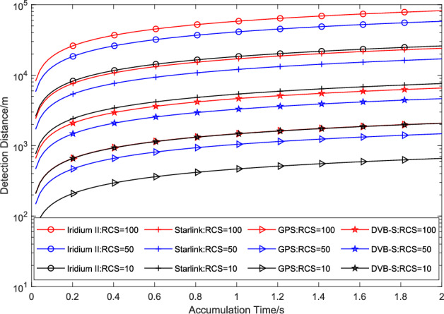
Relationships between the maximum detection range and the coherence time and RCS for the PR using the Iridium, Starlink, GPS, and DVB-S signals.
Analysis of the ambiguity function
Obtaining the frame structure of the signal is a prerequisite for performing ambiguity function analysis. Figure 4 shows the TDMA frame structure of the Iridium user link. The TDMA frame length of the Iridium signal is 90 ms, with an average transmission of 2250 symbols in the entire time slot; each symbol length is 0.04 ms, the symbol rate is 25 ksps, and the data rate is 50 kbps. The allocation time slot for the simplex channel is 20.32 ms, whereas the simplex channel signal for the downlink user link in the actual Iridium signal is 6.5–20.32 ms. The duplex channel occupies four 8.28 ms uplink time slots and four 8.28 ms downlink time slots.
Fig. 4.

Iridium user-link TDMA frame structure.
Figure 5 shows the generation technology and unified frame format of Iridium physical layer signals34. Each channel consists of three parts: a fixed preamble, a unique word, and a payload. The preamble is an unmodulated single tone signal used for carrier synchronization and auxiliary signal acquisition and detection. The unique word is a BPSK modulation signal, which is used to correct phase rotation caused by Iridium signal propagation and filter processing, with a fixed length of 12 symbols and a simplex channel independent character of 789H;
Fig. 5.
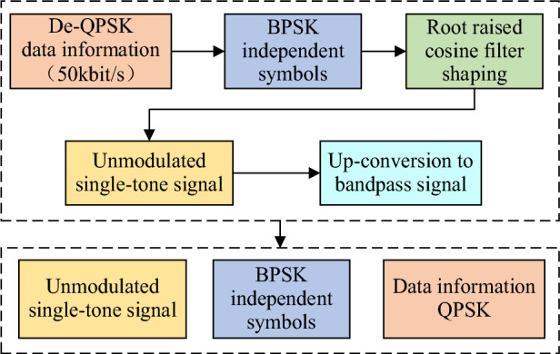
Iridium physical layer channel frame format.
The ambiguity function reflects the measurement accuracy and resolution of the signal emitted by the radar in two dimensions: distance (time) and velocity (frequency). The expression of the ambiguity function is33:
 |
3 |
where  represents the latency and
  represents the Doppler frequency.
The resolution of the distance and frequency is determined by the equivalent bandwidth and accumulation time of the signal, respectively. The wider the frequency band occupied by the signal is, the greater the distance resolution performance. The longer the accumulation time of the signal is, the narrower the width of the ambiguity function in the frequency domain is, and the higher the frequency resolution performance is.
Figure 6 shows the ambiguity function of the Iridium signal. Figure 7 shows the Doppler and time delay profiles of its ambiguity function. The symbol rate of the Iridium signal is 25 ksps, and the roll-off coefficient of the shaping filter is 0.4. Each symbol is assumed to sample 10 points at a sampling frequency of 250 kHz.
Fig. 6.
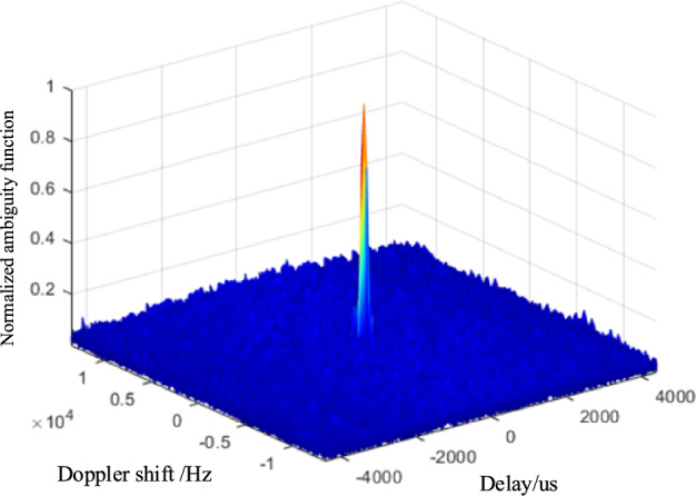
STL signal ambiguity function.
Fig. 7.

Doppler and delay dimensions of the STL signal ambiguity function: (a) Doppler dimension (velocity); (b) delay dimension (distance).
As shown in Fig. 6, the Iridium signal has a “pin-like” ambiguity function. According to resolution theory, the Doppler resolution of a signal is inversely proportional to the coherence accumulation time. Figure 7 shows that the Iridium satellite signal has good Doppler characteristics, with a very narrow peak in the time delay dimension (distance) and excellent range resolution capability. Although there are secondary peaks in the Doppler dimension (velocity), the amplitude is relatively low. In summary, Iridium signals are suitable as external radiation sources and can provide a considerable detection range and accuracy for networked receivers. In summary, the Iridium signal is suitable as an external radiation source and can provide a considerable detection range and accuracy for radar receivers.
NuDE-mECA for PR using the Iridium satellite signal
Subsection signal model
The reference channel signal includes direct waves, multipath clutter, and noise. The echo channel signal includes direct waves, multipath clutter, target echoes, and noise. Assuming that  is the direct wave signal, the reference channel signal can be represented as:
 |
4 |
where  is the amplitude of the direct wave in the reference channel,
  is the number of multipath clutter in the reference channel,
  is the amplitude of the
  -th multipath clutter in the reference channel,
  is the delay of the
  -th multipath clutter in the reference channel, and
  is the total noise in the reference channel.
The echo channel signal is represented as:
 |
5 |
where  is the amplitude of the direct wave in the echo channel,
  is the number of multipath clutter in the echo channel,
  is the amplitude of the
  -th multipath clutter in the echo channel,
  is the delay of the
  -th multipath clutter in the echo channel,
  is the amplitude of the
  -th target in the echo channel,
  is the time delay of the
  -th target in the echo channel,
  is the Doppler frequency of the
  -th target in the echo channel, and
  is the total noise in the echo channel.
Background of the multichannel extended cancellation algorithm
In practical applications, the echo signals received by monitoring channels are accompanied by interference, such as rigid waves and Doppler broadening clutter. The broadening range is related to the wind speed, terrain, sea conditions, receiver parameters, etc. Regarding the issue of clutter Doppler broadening, the echo signal model in Eq. (4) is rewritten as follows:
 |
6 |
where  is the Doppler frequency of the
  -th multipath clutter in the echo channel.
The ECA algorithm was first proposed by Colone et al.18. Its principle is to project the signal onto a subspace orthogonal to the clutter to filter out zero-frequency multipath clutter. Reference18 elaborates on the derivation process of ECA, while this paper focuses on the NuDE-mECA algorithm. Assuming that the noise is zero-mean white Gaussian noise and uncorrelated with the signal, the orthogonal condition means that the clutter subspace is mutually orthogonal to the target signal subspace and the noise subspace, ensuring that no target information is lost during the cancellation process.
The cost function of the LS algorithm can be extended to:
 |
7 |
The reference matrix is multiplied by  diagonal matrices to represent the frequency shift in
  Doppler units, where
  is the Doppler cancellation range. The
  -th diagonal matrix is denoted as
 |
8 |
A reference matrix is constructed at the frequency shift of the p-th Doppler unit using  :
:
 |
9 |
Write Eq. (6) in vector form:
 |
10 |
Among them,  ,
,  , and
, and  .
.
The weight coefficients obtained by solving the cost function are as follows:
 |
11 |
This is one example of an equation:
 |
12 |
Design of the NuDE-mECA algorithm
The multichannel ECA can effectively suppress clutter within the cancellation range and detect targets outside the cancellation range in Doppler broadening scenarios, but it is difficult to distinguish weak clutter and targets within the cancellation range, and performing indiscriminate cancellation on all Doppler frequencies greatly increases computational complexity. Uniform Doppler extraction is the most direct and simple method for reducing computational complexity. However, in practical applications, the uniform Doppler extraction ECA has difficulty maintaining suppression performance while reducing computational complexity. Therefore, this section proposes a nonuniform Doppler extraction-enhanced multichannel extensive cancellation algorithm (NuDE-mECA), which aims to achieve optimal clutter suppression with minimal Doppler extraction without affecting the suppression performance of the multichannel ECA.
Theoretical foundation and workflow of the NuDE-mECA algorithm
Figure 8 shows the flowchart of the NuDE-mECA. This algorithm divides Doppler extraction into two steps based on reference matrix column decomposition. The first step is to roughly extract strong clutter, and the second step is to cancel weaker clutter one by one. Below is an explanation of the key steps in the algorithm.
Fig. 8.

Block diagram of the NuDE-mECA.
Reference matrix column decomposition in multichannel ECA
According to Eq. (12), the output of the multichannel ECA is as follows:
 |
13 |
The projection matrix of the clutter subspace is denoted as  , with a size of
  . The reference signal is time extended to obtain the reference matrix
  . After performing Doppler dimension expansion, the reference matrix suitable for Doppler broadening scenarios is obtained, denoted as
  , with a size of
  . The reference matrix is decomposed into any column
  in
in  , and the remainder is represented as
  . The reconstructed reference matrix
  can be represented as
  ; then,
  can be represented as
 |
14 |
If  is used to represent the projection matrix of the clutter subspace corresponding to the reference matrix of part
  ,
,  can be expressed as:
 |
15 |
 represents:
 |
16 |
Assuming that  , we have:
 |
17 |
where  is as follows:
 |
18 |
Then,  is:
is:
 |
19 |
 and
and  have the same form of expression; it can be inferred that by decomposing the reference matrix into any second column
  in
in  ,
,  can be expressed as:
 |
20 |
The reference matrix  is decomposed into columns until the last column
  , and
, and  can be expressed as:
 |
21 |
where  ,
,  , and
, and  are as follows:
 |
22 |
 |
23 |
 |
24 |
Figure 9 shows a schematic diagram of the multichannel ECA in the clutter suppression process, where the reference matrix is unfolded in columns to achieve step-by-step suppression. There is no correlation between columns in the reference matrix, the suppression order can be customized during step-by-step suppression, and execution can be stopped at any stage. This paper proposes a nonuniform Doppler extraction technique based on multichannel ECA to perform the first Doppler frequency extraction on strong clutter and construct a new reference matrix (only selecting columns related to strong clutter) for the first clutter cancellation. Through the second Doppler frequency identification, weaker clutter is eliminated one by one.
Fig. 9.

Reference matrix column decomposition in the multichannel ECA.
First identification and extraction of the strong clutter frequency
Figure 10 shows the first frequency recognition extraction step, which is explained as follows:
Fig. 10.

First Doppler frequency extraction process.
① Calculate the mutual ambiguity function between the sampled reference signal and the echo signal. According to the definition of the ambiguity function in Eq. (3), the discrete sampling is transformed into:
 |
25 |
where  is the cross-correlation product function,
  is a sampling unit with different time delays, and
  is a unit with different Doppler resolutions.
② At each Doppler frequency, take the maximum value within the range of distance dimension cancellation to obtain all peak values on the Doppler plane. The peak value obtained from the distance dimension at the  -th Doppler frequency is denoted as
  . Sort
  from large to small and represent the Doppler frequency sets corresponding to each peak after statistical sorting using matrix
  .
.
③ Extract the corresponding Doppler frequencies with a clutter-to-noise power ratio greater than 1 and place them in set  .
.
Refactoring reference matrix 
Figure 11 illustrates the reference matrix reconstruction process of different algorithms. Specifically, the top-left diagram corresponds to the ECA algorithm, the top-right diagram to the multichannel ECA algorithm, and the bottom diagram to the proposed NuDE-mECA algorithm. In the reference matrix reconstruction diagram of the NuDE-mECA algorithm, the red regions indicate the extracted Doppler frequencies of clutter. As shown in Fig. 11, when the Doppler frequency is not extracted, the reference matrix  of the multichannel ECA is obtained by multiplying the diagonal matrix
  corresponding to
  Doppler frequencies by the reference matrix
  . The reference matrix of the algorithm in this paper is reconstructed from the
  set obtained from the first extraction of the Doppler frequency to obtain
  , where
  can be expressed as
 |
26 |
Fig. 11.

Reference matrix reconstruction.
The pseudocode for the Nonuniform Doppler Extraction-enhanced Multichannel Extensive Cancellation Algorithm is shown in Table 4.
Table 4.
Pseudocode for the NuDE-mECA.
| Algorithm: NuDE-mECA | |
|---|---|
Input:  , ,  , ,
| |
Output: Output signal after clutter suppression 
| |
| 1 | Compute the mutual ambiguity function  according to Eq. (25); according to Eq. (25); |
| 2 | Take the maximum value  within the range of distance dimension cancellation, for each Doppler frequency ; within the range of distance dimension cancellation, for each Doppler frequency ; |
| 3 | Sort the peak values and save to matrix  ; ; |
| 4 | Take the first  Doppler frequencies as the first frequency extraction set Doppler frequencies as the first frequency extraction set  , the power ratio of clutter to noise is greater than 1; , the power ratio of clutter to noise is greater than 1; |
| 5 |
//Refactoring the reference matrix for the first frequency extraction; For Extract the relevant columns corresponding to End For |
| 6 |
//Eliminating clutter on each frequency in set For For Solve the orthogonal projection of End For End For |
| 7 |
//Compute the clutter suppression ratio For If Extract Else Break End For |
| 8 | Return 
|


Computational complexity of the NuDE-mECA algorithm
Table 5 compares the computational complexity of the multichannel ECA, uniform Doppler extraction multichannel ECA, and nonuniform Doppler extraction-enhanced multichannel ECA.
Table 5.
Comparison of the calculation quantity.
| Algorithm | Complexity |
|---|---|
| Multichannel ECA |  |
| Uniform Doppler extraction mECA |  |
| NuDE-mECA |  |
Calculation complexity of the multichannel ECA: the dimension of the clutter subspace  is
is  , the dimension of
  is
is  , and the expression of the algorithm is
  . The multiplication factor of the multichannel ECA is
  .
.
Calculation complexity of uniform Doppler extraction multichannel ECA: Assuming that the Doppler frequency interval is  , the number of extracted Doppler frequencies is
  . Similarly, the multiplication factor for uniform extraction can be derived as
  .
.
The calculation complexity of the nonuniform Doppler extraction-enhanced multichannel ECA is as follows: the complex product of the mutual ambiguity function is  ,
,  represents the total number of delays, the complexity of the sorting process is
  , the number of extracted Doppler frequencies is
  , and the total complexity of the proposed algorithm is
  . Compared with the computational complexity of clutter cancellation, the computational complexity of calculating mutual ambiguity functions and sorting algorithms can be neglected. In practical applications, ambiguity functions can be used for fast algorithm calculations, which can further reduce computational complexity.
According to Table 5, the main factor affecting the computational complexity of the three algorithms is the size of the Doppler dimension suppression order  . Given that the number of sampled data points
  within 1 s is
  and assuming that
  is 20, the range of variation for
  is 0:400. According to the multiplication factor
  of the multichannel ECA, the curve of the total multiplication factor changing with the Doppler dimension suppression order
  is shown in Fig. 12.
Fig. 12.
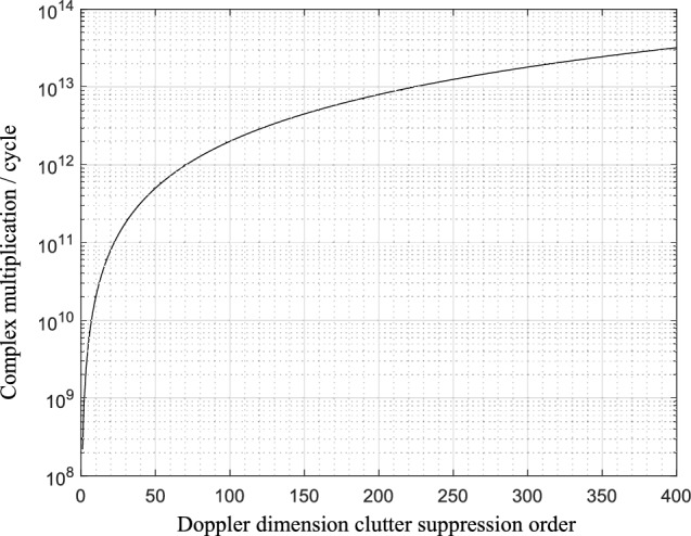
Curve of the variation in the computational complexity of the multichannel ECA with the Doppler suppression range.
As shown in Fig. 12, when the Doppler dimension suppression order is 400, the multiplication of the multichannel ECA without Doppler extraction reaches  . In reality, the Doppler that needs to be cancelled is on the order of several hundred to several thousand. The computational cost of uniform Doppler extraction depends on the selection of the Doppler interval. When the extraction ratio is
  , the computational cost decreases by
  times. If the Doppler interval is too small, it will result in a less significant decrease in computational complexity, whereas if the Doppler interval is too large, it will increase the probability of strong clutter leakage cancellation. The calculations of ambiguity functions and sorting algorithms in the proposed algorithm require relatively few computations, which can be ignored. The factor that affects the total computational complexity is the number of Doppler frequency extractions
  , which depends on the actual Doppler broadening of the clutter. In most cases,
  is much smaller than P. When the extraction ratio is
  , the computational complexity is reduced by
  times compared with that of the ECA. When the extraction ratio is 1%, the computational complexity is reduced by approximately
  compared with that of the ECA. Therefore, the proposed algorithm can reduce computational complexity while ensuring its suppression performance.This significant reduction in computational load enables the algorithm to process echo signals within a reasonable time frame, meeting the latency requirements of near-real-time systems. Meanwhile, the algorithm maintains excellent clutter suppression performance and detection capability for near-field low-speed targets, ensuring that the processed results can effectively support subsequent target localization and tracking tasks.
Results
To comprehensively validate the performance of the proposed NuDE-mECA algorithm, this chapter conducts comparative simulations between the traditional multichannel ECA and the NuDE-mECA. First, the target detection capabilities of the multichannel ECA are analyzed under four typical scenarios. The suppression performance of the NuDE-mECA is subsequently evaluated in scenarios with increased clutter complexity.
Target detection capabilities of the multichannel ECA for reference
Parameter settings
Table 6 shows the Doppler broadening clutter-related parameters in this simulation scenario. The multipath delay is set to 0 ~ 20 µs, and the clutter signal-to-noise ratio is set to a random number between -5 ~ 20 dB. The cancellation range is set as follows: the distance dimension M is 25, the Doppler cancellation interval is set to 1 Hz, and the cancellation range is [-400,400] Hz.
Table 6.
Simulated parameters of the Doppler broadening clutter.
| Number | Delay/us | Doppler Shift/Hz | SNR/dB |
|---|---|---|---|
| 1 | 0 | 0 | 60 |
| 2 | 2, 4, …, 20 | 0 | 0 ~ 20 |
| 3 | 2, 4, …, 20 | 120 | 0 ~ 10 |
| 4 | 2, 4, …, 20 | -120 | 0 ~ 10 |
| 5 | 2, 4, …, 20 | 360 | -5 ~ 5 |
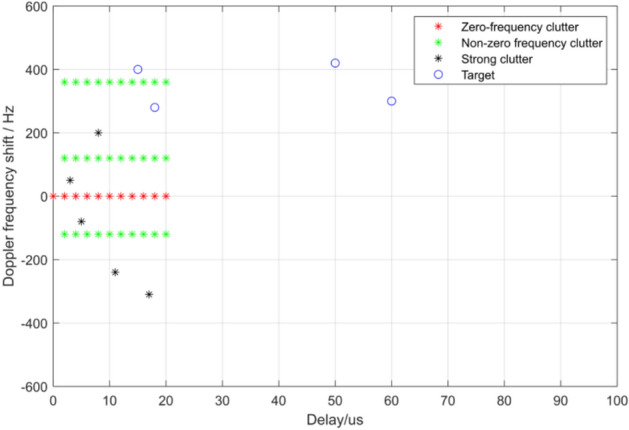
Table 7 provides the target parameters. The targets are divided into the following four scenarios: (1) far-field high-speed target; (2) near-field high-speed target; (3) far-field low-speed target; and (4) near-field low-speed target. The four simulation scenarios are shown in Fig. 13.
Table 7.
Simulated parameters of the target echo.
| Target | Delay/us | Doppler Shift/Hz | SNR/dB |
|---|---|---|---|
| (1) | 50 | 520 | -14 |
| (2) | 15 | 500 | -4 |
| (3) | 60 | 300 | -15 |
| (4) | 18 | 280 | -5 |
Fig. 13.

Relative positions of the targets and clutter in four special scenarios: (a) far-field high-speed target; (b) near-field high-speed target; (c) far-field low-speed target; (d) near-field low-speed target.
Numerical results of the multichannel ECA
We simulate and analyze the clutter suppression effect of multichannel ECA in four scenarios. As shown in Fig. 14, the algorithm can effectively suppress Doppler broadening clutter within the cancellation range and detect targets outside the cancellation range, but it will suppress low-speed targets in the near area.
Fig. 14.

Ambiguity function diagram of the time delay dimension after the multichannel ECA is suppressed in four special scenarios: (a) far-field high-speed target; (b) near-field high-speed target; (c) far-field low-speed target; (d) near-field low-speed target.
Target detection capabilities of the NuDE-mECA algorithm
Parameter settings
To compare the suppression performance of the NuDE-mECA and multichannel ECA, 5 different intensities of strong clutter are added based on the simulation scenario in Sect. “Target detection capabilities of the multichannel ECA for reference”. The CNR of the echo channel is 20 dB. Table 8 presents the newly added strong clutter parameters. Figure 15 shows the simulation diagram in this scenario.
Table 8.
Parameters of newly added strong clutter in the echo channel.
| Number | Delay/us | Doppler shift/Hz | CNR/dB |
|---|---|---|---|
| Strong clutter 1 | 3 | 50 | 20 |
| Strong clutter 2 | 5 | −80 | 18 |
| Strong clutter 3 | 8 | 200 | 15 |
| Strong clutter 4 | 11 | −240 | 13 |
| Strong clutter 5 | 17 | −310 | 10 |
Fig. 15.
Simulation diagram.
Numerical results of the NuDE-mECA algorithm
Under ideal conditions, the cancellation output contains only target echoes and noise. Figure 16 shows the mutual ambiguity function diagram of the output under ideal cancellation conditions. As shown in the figure, the basis of the mutual ambiguity function under ideal cancellation conditions is -20.56 dB, and the signal-to-noise ratios of the four targets are 20.56 dB, 20.22 dB, 19.24 dB, and 19.59 dB.
Fig. 16.

Ambiguity function for the ideal suppression case: (a) front view; (b) delay dimension profile.
Figure 17 shows the clutter suppression effect of the NuDE-mECA when the clutter suppression threshold is 18. According to Fig. 17b, the basis of the mutual ambiguity function is -19.98 dB, and the clutter effect is only 0.58 dB greater than the ideal state. The clutter is effectively suppressed, and the target signal-to-noise ratios are 19.32, 19.98, 19.33, and 17.98 dB. Compared with the ideal cancellation output, the average signal-to-noise ratio of the target is only 0.75 dB lower, basically achieving the ideal clutter suppression state.
Fig. 17.

Ambiguity function diagram after suppression by the NuDE-mECA: (a) front view; (b) delay dimension profile.
Figure 18 shows the results of 2D-CFAR detection after suppression by the NuDE-mECA. The results show that the algorithm can effectively suppress clutter and has the ability to distinguish weak clutter and low-speed targets in the near area.
Fig. 18.

2D-CFAR detection results after suppression by the NuDE-mECA: (a) front view; (b) vertical view.
Threshold impact on the performance of the NuDE-mECA algorithm
This section presents an analysis of the impact of clutter suppression threshold settings on the performance of the NuDE-mECA. Tables 9 and 10 list the randomly generated clutter parameters, while Table 11 provides the randomly generated target echo parameters. The cancellation order of the time delay dimension is set to 30.
Table 9.
Clutter parameters.
| Clutter | 1 | 2 | 3 | 4 | 5 | 6 | 7 | 8 | 9 | 10 |
|---|---|---|---|---|---|---|---|---|---|---|
| Delay/us | 0 | 1 | 3 | 4 | 7 | 8 | 10 | 11 | 13 | 16 |
| Doppler/Hz | 0 | −8 | 10 | −18 | −29 | 32 | −46 | 64 | 92 | −101 |
| CNR/dB | 25 | 15 | 12 | 7 | 19 | 9 | 6 | 21 | 17 | 4 |
Table 10.
Clutter parameters (continued).
| Clutter | 11 | 12 | 13 | 14 | 15 | 16 | 17 | 18 | 19 | 20 |
|---|---|---|---|---|---|---|---|---|---|---|
| Delay/us | 17 | 18 | 21 | 22 | 24 | 25 | 26 | 27 | 29 | 30 |
| Doppler/Hz | 208 | 363 | 311 | −190 | 278 | −316 | 303 | 179 | −213 | 243 |
| CNR/dB | −4 | −3 | −5 | −3 | −1 | −4 | 0 | −2 | −3 | −2 |
Table 11.
Target parameters.
| Target | 1 | 2 | 3 | 4 | 5 |
|---|---|---|---|---|---|
| Delay/us | 15 | 18 | 27 | 42 | 50 |
| Doppler/Hz | −584 | 536 | −385 | −573 | 775 |
| CNR/dB | −12 | −18 | −20 | −15 | −19 |
Figure 19 shows a schematic diagram of the simulation scenario. Figure 20 shows the blur function of the signal before NuDE-mECA suppression.
Fig. 19.
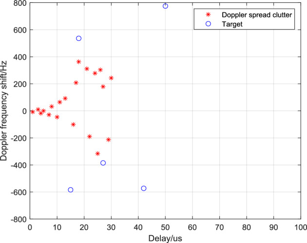
Simulation scene.
Fig. 20.
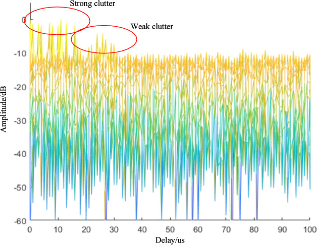
Delay dimension of the ambiguity function diagram before suppression.
Figure 21 shows the suppression effect of NuDE-mECA at different threshold values (time-delayed ambiguity function).
Fig. 21.

Ambiguity function of the delay dimension suppressed by the NuDE-mECA at different threshold values: (a) the threshold is 14 dB; (b) the threshold is 15 dB; (c) the threshold is 16 dB; (d) the threshold is 17 dB; (e) the threshold is 18 dB; (f) the threshold is 19 dB; (g) the threshold is 20 dB; (h) the threshold is 21 dB.
From Fig. 22, it can be observed that: (1) When the suppression threshold is set below 14 dB, after the first frequency extraction and suppression by NuDE-ECA, the clutter suppression ratio already exceeds the set suppression threshold, and thus the second frequency extraction will not be performed; (2) When the suppression threshold is set between 14 and 19 dB, during the second frequency extraction of NuDE-ECA, the weak clutter is not completely suppressed due to the insufficiently high threshold setting. Although targets have emerged when the suppression threshold is between 17 and 19 dB, they are still aliased with clutter and cannot be effectively distinguished; (3) When the suppression threshold is set to 19 dB and 20 dB, targets can all be effectively detected. However, considering that increasing the threshold will increase the computational load, 19 dB is regarded as the optimal threshold in this experiment; (4) When the suppression threshold exceeds the optimal value, set to 21 dB, as the algorithm continues to identify and cancel clutter within the time-delay cancellation range, targets within this range are mistaken for clutter and suppressed, resulting in missed alarms; (5) With a further increase in the threshold value, NuDE-ECA will perform indiscriminate cancellation within the time-delay cancellation range, which is equivalent to the ineffectiveness of the algorithm’s Doppler extraction. At this point, the NuDE-ECA algorithm is equivalent to the multichannel ECA algorithm.
Fig. 22.
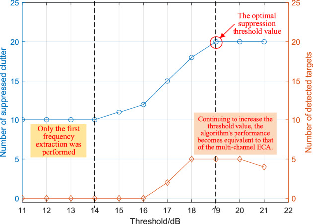
Suppression effect of NuDE-mECA with different detection thresholds.
In summary, the setting of the clutter suppression threshold in the NuDE-ECA algorithm determines the performance of the algorithm. According to the principle of clutter suppression, theoretically, the extracted clutter suppression ratio threshold should not exceed the clutter-to-noise ratio (CNR) of the echo channel. However, the main challenge in practical applications lies in the inability to accurately obtain this value. To enhance the practicality of the NuDE-ECA algorithm, prior to clutter suppression, sufficient preprocessing and analysis of the signal should be conducted to estimate the maximum clutter suppression ratio by extracting signal features, which serves as the reference threshold. This process requires integrating prior knowledge of clutter in specific application scenarios to establish a dynamic adjustment mechanism.
Discussion
PR has the advantages of no electromagnetic pollution, low cost, small size, low power consumption, and strong maneuverability and has extremely broad application prospects. Compared with ground-based and medium- and high-orbit satellite signal external emitter radars, the low link loss and stable coverage of LEO communication satellite signals, together with the large-scale deployment of LEO satellite internet around the world, give LEO communication satellite signal PR great application value. Among them, the Iridium satellite network has the advantages of many satellites, global deployment with wide coverage, high transmission power, low link loss, easy networking and coordination of radiated signals, stable signal sources, and the ability to provide global all-weather and time-domain stable coverage. They can provide considerable detection distance and accuracy for passive target detection.
Based on an in-depth analysis of the detection performance of the Iridium satellite external radiation source radar system, this paper proposes a nonuniform Doppler extraction-enhanced multichannel extensive cancellation algorithm (NuDE-mECA) for the suppression of direct wave and Doppler broadening clutter, starting from the Doppler order. This algorithm introduces a two-stage nonuniform Doppler extraction technique based on the multichannel extended cancellation algorithm, which performs differentiated cancellation of strong and weak clutter through two Doppler extractions. The simulation results show that the proposed algorithm reduces the Doppler dimension suppression order and greatly reduces the computational complexity; on the other hand, it improves the resolution between weak clutter and low-speed targets within the cancellation range.
The proposed NuDE-mECA algorithm demonstrates good versatility and is applicable to various satellite systems, including GPS, BeiDou, GLONASS, and others. However, in practical applications, corresponding parameter adjustments and data preprocessing optimizations should be performed according to the signal characteristics of different satellite systems. For instance, high-orbit satellite signals require longer coherent accumulation time to compensate for the power disadvantage due to their lower received power, while other low-orbit satellite signals necessitate resetting the threshold parameters for frequency-domain extraction based on their specific Doppler dynamic range. Additionally, differences in signal modulation schemes and frequency band characteristics among various satellite systems must be considered during algorithm implementation. In future research, the authors will focus on exploring the application adaptability of this algorithm in multiple satellite systems, and conduct in-depth studies on the technical challenges brought by multi-system fusion processing, including but not limited to key issues such as multi-system time–frequency reference unification and inter-signal interference suppression, so as to further enhance the practicality of the algorithm in complex multi-satellite system environments.
Author contributions
Conceptualization, H.F., Z.Z., Y.L., T.F., J.L., X.J. and H.C.; methodology, H.F. and Z.Z.; software, H.F. and Z.Z.; validation, H.F. and Z.Z.; formal analysis, H.F. and Z.Z.; investigation, Y.L., T.F. and J.L.; writing—original draft preparation, H.F., Z.Z., Y.L., T.F. and J.L.; writing—review and editing, H.F., Z.Z., Y.L., T.F., X.J. and H.C.
Funding
This work was supported by the National Key Research and Development Program of China under Grant 2023YFB3306900; The National Natural Science Foundation of China under Grant U21A20448; The Fundamental Research Funds for the Central Universities under Grant 2024CDJGF-012.
Data availability
The datasets used and/or analysed during the current study are available from the corresponding author on reasonable request.
Declarations
Competing interests
The authors declare no competing interests.
Footnotes
Publisher’s note
Springer Nature remains neutral with regard to jurisdictional claims in published maps and institutional affiliations.
Hongwei Fu and Zhang Zhang contributed equally to this work.
Contributor Information
Xin Jian, Email: jianxin@cqu.edu.cn.
Hao Cha, Email: 0909041006@nue.edu.cn.
References
- 1.Kuschel, H. Approaching 80 years of passive radar. 2013 International Conference on Radar - Beyond Orthodoxy: New Paradigms in Radar, RADAR 2013, Adelaide, SA, Australia. 10.1109/RADAR.2013.6651987. (2013).
- 2.Song, J., He, Y., Cai, F. & Tang, X. Overview of passive radar technology based on non-cooperative radar illuminator. Syst. Eng. Electron.10.3321/j.issn:1001-506X.2009.09.028 (2009). [Google Scholar]
- 3.Zheng, H., Wang, J., Jiang, S., Wu, X. & Gu, X. Passive bistatic radar 1–10 (National Defense Industry Press, 2017). [Google Scholar]
- 4.Wan, X. et al. Research progress and development trend of the multi-illuminator-based passive radar. J. Radars9(6), 939–958. 10.12000/JR20143 (2020). [Google Scholar]
- 5.Veremyev, V., Vorobev, E. & Kokorina, Y. Feasibility study of air target detection by passive radar using satellite-based transmitters. 2019 IEEE Conference of Russian Young Researchers in Electrical and Electronic Engineering (EIConRus), 154–157. 10.1109/eiconrus.2019.8656630. (St Petersburg Electrotechn Univ, 2019).
- 6.Huang, C., Li, Z., Wu, J., Huang, Y., Yang, H. & Yang, J. Multistatic Beidou-based passive radar for maritime moving target detection and localization. IEEE International Geoscience and Remote Sensing Symposium (IGARSS), 2175–2171. 10.1109/igarss.2019.8900548. (2019).
- 7.Huang, C., Li, Z., Wu, J., Huang, Y., Yang, H. & Yang, J. A long-time integration method for GNSS-based passive radar detection of marine target with multi-stage motions. IEEE International Geoscience and Remote Sensing Symposium (IGARSS), 2815–2818. 10.1109/IGARSS39084.2020.9324042. (2020).
- 8.Li, Z., Huang, C., Wu, J. & Yang, J. Investigation and first experiment of BeiDou-based passive radar vessel target imaging. 2022 3rd URSI Atlantic and Asia Pacific Radio Science Meeting (AT-AP-RASC), 1–4. 10.23919/AT-AP-RASC54737.2022.9814205. (2022).
- 9.Li, Z. et al. BeiDou-based passive multistatic radar maritime moving target detection technique via space-time hybrid integration processing. IEEE Trans. Geosci. Remote Sens.60, 1–13. 10.1109/TGRS.2021.3128650 (2022). [Google Scholar]
- 10.Jiang, Y., Du, K., Yang, Q., Li, Z., Wu, J. & Yang, J. Bistatic SAR spatial-variant motion error compensation method via joint-refocusing of multi-subimages. 2023 6th International Conference on Electronics Technology (ICET), Chengdu, China, 190–195. 10.1109/ICET58434.2023.10211310. (2023).
- 11.Marques, P., Ferreira, A., Fortes, F., Sampaio, P., Rebelo, H. & Reis, L. A pedagogical passive RADAR using DVB-S signals. 2011 3rd International Asia-Pacific Conference on Synthetic Aperture Radar (APSAR), Seoul, Korea (South), 1–4. (2011).
- 12.Sun, Z., Wang, T., Jiang, T. & Chen, C. Analysis of the properties of DVB-S signal for passive radar application. 2013 International Conference on Wireless Communications and Signal Processing, Hangzhou, China, , 1–5. (2013).
- 13.Yu, X., Wang, M., Wang, T., Chen, C. & Chen, W. Design and implementation of an experimental ABS-S based passive radar. 2013 International Conference on Wireless Communications and Signal Processing, Hangzhou, China, 1–4. 10.1109/WCSP.2013.6677165. (2013).
- 14.Lyu, X., Stove, A., Gashinova, M. & Cherniakov, M. Ambiguity function of inmarsat BGAN signal for radar application. Electron. Lett.52(18), 1557–1559. 10.1049/el.2016.1400 (2016). [Google Scholar]
- 15.Stove, A., Gashinova, M., Hristov, S. & Cherniakov, M. Passive maritime surveillance using satellite communication signals. IEEE Trans. Aerosp. Electron. Syst.53(6), 2987–2997. 10.1109/TAES.2017.2722598 (2017). [Google Scholar]
- 16.Daniel, L. et al. Design and validation of a passive radar concept for ship detection using communication satellite signals. IEEE Trans. Aerosp. Electron. Syst.53(6), 3115–3134. 10.1109/TAES.2017.2728978 (2017). [Google Scholar]
- 17.Xu, Y., Tao, R., Wang, Y. & Dan, T. Using LMS adaptive filter in direct wave cancellation. J. Beijing Inst. Technol.12(4), 425–428. 10.3969/j.issn.1004-0579.2003.04.020 (2003). [Google Scholar]
- 18.Colone, F., Cardinali, R. & Lombardo, P. Cancellation of clutter and multipath in passive radar using a sequential approach. 2006 IEEE Conference on Radar, Verona, NY, USA, 1–7. 10.1109/RADAR.2006.1631830. (2006).
- 19.Colone, F., O’Hagan, D., Lombardo, P. & Baker, C. A multistage processing algorithm for disturbance removal and target detection in passive bistatic radar. IEEE Trans. Aerosp. Electron. Syst.45(2), 698–722. 10.1109/TAES.2009.5089551 (2009). [Google Scholar]
- 20.Zhao, Z., Wan, X., Shao, Q., Gong, Z. & Cheng, F. Multipath clutter rejection for digital radio mondiale-based HF passive bistatic radar with OFDM waveform. IET Radar Sonar Navig.6(9), 867–872. 10.1049/iet-rsn.2012.0011 (2012). [Google Scholar]
- 21.Colone, F., Palmarini, C., Martelli, T. & Tilli, E. Sliding extensive cancellation algorithm for disturbance removal in passive radar. IEEE Trans. Aerosp. Electron. Syst.52(3), 1309–1326. 10.1109/TAES.2016.150477 (2016). [Google Scholar]
- 22.Liu, Y., Lv, X. & Yang, P. Batch version of extensive cancellation algorithm for clutter mitigation in frequency domain of passive radar. J. Radars5(3), 293–301. 10.12000/JR15098 (2016). [Google Scholar]
- 23.Chen, W., Wan, X., Zhang, X., Rao, Y. & Cheng, F. Parallel implementation of multi-channel time domain clutter suppression algorithm for passive radar. J. Radars3(6), 686–693. 10.12000/JR14157 (2014). [Google Scholar]
- 24.Zhao, Z., Zhu, S., Xu, C. & Chen, L. Non-zero Doppler shift multipath clutter suppression in DRM-based passive bistatic radar. Modern Radar10.16592/j.cnki.1004-7859.2017.05.010 (2017). [Google Scholar]
- 25.Schupbach, C., Paine, S. & O’Hagan, D. Efficient direct signal cancellation for FM-based passive radar. 2020 IEEE Radar Conference (RadarConf20), Florence, Italy, 1–5. 10.1109/radarconf2043947.2020.9266713. (2020).
- 26.Lyu, X., Xu, J. & Wang, J. Clutter cancellation in passive radar from the perspective of maximum likelihood. 2021 CIE International Conference on Radar (Radar), Haikou, Hainan, China, 2808–2811. 10.1109/Radar53847.2021.10028202. (2021).
- 27.Zhao, X., Liu, P., Wang, B. & Jin, Y. GPU-accelerated signal processing for passive bistatic radar. Remote Sens.15(22), 5421–5421. 10.3390/rs15225421 (2023). [Google Scholar]
- 28.Zhao, Dawei. Research on detection method of faint target of passive radar based on differential. Doctor of Philosophy, Xidian University, Xi’an, China. 10.27389/d.cnki.gxadu.2023.000225. (2023).
- 29.Sui, J., Wang, J., Gao, J. & Fan, X. An extensive cancellation algorithm via overlapping subband for time-varying clutter suppression in passive bistatic radar. IEEE Trans. Aerosp. Electron. Syst.60(4), 5169–5185. 10.1109/TAES.2024.3386156 (2024). [Google Scholar]
- 30.Jia, D., Wen, B., Shi, J., Luo, Y. & Wang, H. A Parallel processing technology for clutter suppression in external radiation source radar based on ldlt decomposition. Radio Eng.54(01), 150–156. 10.3969/j.issn.1003-3106.2024.01.020 (2024). [Google Scholar]
- 31.Cui, Z., Yue, F., Tian, R. & Zhang, S. Research on positioning technology based on Iridium burst signal. GNSS World China46(2), 77–85. 10.12265/j.gnss.2020121503 (2021). [Google Scholar]
- 32.Xie, J. High Velocity Targets Detection Technology Based on Opportunity Illumination (University of Electronic Science and Technology of China (UESTC), Chengdu, China, 2018). [Google Scholar]
- 33.Yang, J., Liu, Z. & Zhu, X. The performances analysis of GPS signals for passive radar. J. Electron. Inf. Technol.29(5), 1083–1086 (2007). [Google Scholar]
- 34.Liu, Y. The first 10 satellites of Iridium NEXT launched successfully. Space Int.4, 52–54. 10.3969/j.issn.1009-2366.2017.04.010 (2017). [Google Scholar]
Associated Data
This section collects any data citations, data availability statements, or supplementary materials included in this article.
Data Availability Statement
The datasets used and/or analysed during the current study are available from the corresponding author on reasonable request.