

Abstract
Over the past decades, the development of CT technologies has been largely driven by the need for cardiac imaging but the temporal resolution remains insufficient for clinical CT in difficult cases and rather challenging for preclinical CT since small animals have much higher heart rates than humans. To address this challenge, here we report a Semi-stationary Multi-source AI-based Real-time Tomography (SMART) CT system. This unique scanner is featured by 29 source-detector pairs fixed on a circular track to collect X-ray signals in parallel, enabling instantaneous tomography in principle. Given the multisource architecture, the field-of-view only covers a cardiac region. To solve the interior problem, an AI-empowered interior tomography approach is developed to synergize sparsity-based regularization and learning-based reconstruction. To demonstrate the performance and utilities of the SMART system, extensive results are obtained in physical phantom experiments and animal studies, including dead and live rats as well as live rabbits. The reconstructed volumetric images convincingly demonstrate the merits of the SMART system using the AI-empowered interior tomography approach, enabling cardiac CT with the unprecedented temporal resolution of 33ms, which enjoys the highest temporal resolution than the state of the art.
Keywords: Computed tomography (CT), deep learning, multi-source, image reconstruction, real-time, cardiac imaging, preclinical imaging
I. Introduction
Since the first commercial computed tomography (CT) technology was introduced that allowed electrocardiogram (ECG)-gated CT imaging (Electron Beam CT, EBCT) in the early 1990s [1], cardiac CT has become an indispensable tool for diagnosis and treatment of cardiovascular diseases. The current multi-row detector CT (including dual source CT) helps improve image quality and diagnostic performance for many patients. However, patients who often have special conditions such as severe arrhythmia, atrioventricular block, etc., still have contraindications to cardiac CT. Improving temporal resolution is highly desirable to reduce cardiac motion artifacts. In addition to anatomical cardiac CT, CT perfusion (CTP) is a functional imaging technique that relies on high temporal resolution. CTP is mainly used to diagnose cerebral ischemia and tumor heterogeneity [2]. After rapid intravenous injection of contrast agent, continuous CT scanning is performed on a selected slice of interest to monitor local blood perfusion and computes physiological parameters, such as mean transit time (MTT), permeability–surface area product (PS), blood flow, and blood volume. The quality and accuracy of MTT and PS depend on the imaging speed at which an adequate projection dataset is acquired.
CT equipment with extremely high temporal resolution is not only valuable for diagnosis of the human cardiac diseases but also in preclinical research. Rats, rabbits, dogs, etc. are commonly used in preclinical research. Their heart rates (say, 600 beats per minute for a rat) are much higher than that of the human, and result in imaging of the heart and lungs very challenging. Here we report our recently prototyped first-of-its-kind CT scanner to image the heart and lungs of rats and rabbits at high imaging speed.
As a common non-invasive imaging tool, a CT scanner usually contains only one or two source–detector assemblies with a sub-optimal temporal resolution [3]. Over the past decades, major temporal resolution improvements have been made with an increasingly faster rotation speed [4], two tube-detector pairs [5], and advanced reconstruction techniques [6]. Commonly, a CT scanner with a single X-ray source scans at a speed as fast as up to 3 Hz. Ultimately, the centrifugal force limits the scanning speed. Despite the prevalence of CT scanners with rotating gantries in hospitals and clinics, reconstructed images remain suboptimal in challenging cases such as with high and irregular heart rates [7].
Worldwide, cardiovascular diseases (CVDs) are the leading cause of death, taking almost 17.9 million lives annually [8]. CVDs include a group of disorders of the heart and associated vasculature, such as coronary heart disease, cerebrovascular disease, rheumatic heart disease, and other disorders. Four out of five CVD deaths are due to heart attacks and strokes. Dynamic cardiac CT studies demand better technologies and have been a primary driving force for the development of the CT field. Since CT temporal resolution is not sufficiently high, ECG-gating is widely employed to account for a quasi cyclical cardiac motion, improving temporal resolution and minimizing image artifacts. Unfortunately, this approach has major limitations that become most evident in patients with irregular and/or fast heart rates. Furthermore, radiation exposure is high with ECG-gated cardiac CT, given the requirement for continuous overlapped scanning and retrospective data grouping.
Extensive efforts have been made to address these challenges. The system with multiple source-detector chains is a feasible solution. To reach this goal, various system designs were proposed. The rationale is that increasing the number of source-detector pairs in a gantry will reduce the data acquisition time and improve the temporal resolution [9]. The first example is the multisource CT prototype known as the dynamic spatial reconstructor (DSR) [10], which still demands a mechanical scan. Subsequently, several multi-source CT schemes were designed. Liu et al. demonstrated the improved image quality in a simulated five-source cone-beam CT using a Feldkamp-type reconstruction algorithm [11]. Cao et al. proposed an 80 multi-source interior CT architecture that employs three X-ray source arrays and three detectors operated in the interior tomography mode [12]. For these multiple source-based X-ray imaging system designs, a general challenge is how to collect high-quality data and perform interior CT reconstruction [13]. For interior tomography, X-ray beams are restricted to travel through a local region of interest (ROI), with the measurement on the ROI compromised by both surrounding tissues, Poisson noise and Compton scattering [14, 15]. Nevertheless, interior tomography enables utilization of smaller X-ray detectors and provides ultrahigh temporal resolution. Clearly, the multisource interior CT architecture has the potential to achieve all-phase cardiac CT imaging. However, these multiple-source CT cardiac imaging systems have not been prototyped so far because of the complexity of the system engineering, data processing and image reconstruction, as well as the cost incurred in such a highly non-trivial undertaking. However, the voltage of carbon nanotube (CNT) cold cathode X-ray sources becomes the main limitation in practice. The field emission cold cathode X-ray source allows a nearly real-time response, making it an excellent choice for instant CT systems [16, 17]. Innovations in using linear arrays of CNT cold cathode X-ray sources enabled the development of cutting-edge instant CT imaging equipment [18, 19]. For instance, Yang et al. harnessed CNT cold cathode X-ray sources to create a stationary digital breast tomosynthesis system [20]. Quan and Lalush introduced square and hexagonal geometries for a multisource X-ray micro-CT system [18]. Gonzales et al. put forward a rectangular fixed-gantry CT system for airport security inspections [19]. More recently, we introduced an addressable-nanowire cold cathode-based flat-panel X-ray source for instant CT imaging [21]. It is important to note that practical applications of CNT cold cathode X-ray sources are currently constrained by their limited voltage range.
Over recent years, the use of artificial intelligence (AI) [22], specifically deep learning, has become instrumental in the medical imaging field [23]. For dynamic cardiac imaging, the deep learning techniques demonstrated significant potential in reconstructing high-quality images from incomplete and/or compromised measurements [24]. Bello et al. took image sequences of the heart acquired using cardiac MRI to create a time-resolved segmented dynamic volume using a fully convolutional network aided by anatomical shape prior [25]. To provide a high-quality image in phase-contrast magnetic resonance imaging, Vishnevskiy et al. proposed an efficient model-based deep neural reconstruction network to avoid hyperparametric tuning and expensive computational overhead of compressed sensing reconstruction methods for clinical aortic flow analysis [26]. To improve the overall quality of 4D CBCT images, two CNN models, named N-Net and CycN-Net, were proposed in [27].
The state-of-the-art cardiac CT scanner with a wide-area detector covers an entire heart within a single cardiac cycle. For example, the Revolution™ CT scanner (GE HealthCare) achieves a temporal resolution of 140ms [28]. As the posterior left ventricular wall moves at a maximum velocity of 52.5 mm/s, a scan time of 19.1 ms or less is ideal to avoid motion artifacts. If the average mean velocity is considered, the scan time should still be 41.8ms. Currently, even if deep learning is used with the current CT systems, the temporal resolution remains suboptimal. It is feasible to incorporate the deep learning into the multi-source imaging system. Due to the restricted field-of-view (FOV) of the multiple source-detector CT system, one typically encounters the interior CT reconstruction problem.
In this study, we first prototype a Semi-stationary Multisource AI-based Real-time Tomography (SMART) system, where 29 source-detector pairs are fixed on a circular track to collect X-ray signals in parallel, as shown in Figure 1a and Figure 1b. The new system architecture leads to a major improvement in temporal resolution. To achieve high-quality dynamic images from truncated and sparse measurements, we developed the AI-empowered interior tomography approach network, where we utilize the relationship among different timeframes and reconstruct raw time-group average images. Then, the interior CT reconstruction network is trained to recover high-quality deep group-average images from raw time-group average images. Also, the sparsity dictionary was trained from prior deep group-average images and further reconstructed high-quality group-average images using a compressed sensing model. Finally, we obtain the final reconstruction depending on the current measurement and the high-quality group-average prior image. Our SMART imaging system has the highest high temporal resolution so that we can obtain high-quality interior CT images of the heart and lungs in small animal models.
Figure 1.
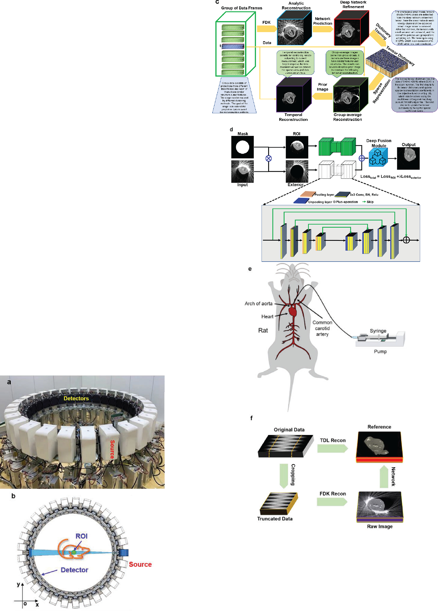
Multi-source “SMART” preclinical CT prototype and reconstruction framework for dyamic image reconstruction. (a) A photograph of the real system; (b) the imaging geometry; (c) the flowchart of the SMART reconstruction framework; (d) the interior CT network in the first SMART reconstruction stage; (e) animal model for contrast injection with dynamic imaging; (f) training, validation and testing for deep neural network-based interior reconstruction.
In contrast to conventional CNT cold cathode X-ray sources utilized in multiple-source CT systems, our innovative SMART system presents several distinctive advantages that significantly enhance its utility and effectiveness in industrial applications. First, our SMART system boasts superior capabilities in terms of high voltage and power output. This attribute is paramount in industrial settings where robustness and efficiency are paramount. By providing elevated levels of voltage and power, our system ensures optimal performance, facilitating more accurate and comprehensive imaging outcomes compared to conventional counterparts. Moreover, the configurational flexibility of our SMART system represents a significant breakthrough. Unlike rigid configurations in traditional setups, our system offers adaptable parameters, enabling operators to customize the distance between the X-ray source, detector, and object. This flexibility empowers users to tailor the field-of-view and spatial resolution according to specific requirements, thereby optimizing imaging precision and versatility across diverse industrial applications. Another key advantage of our SMART system lies in its integration of intelligent reconstruction methods. By incorporating cutting-edge algorithms and computational techniques, our system excels in generating high-quality reconstructed images from a single scan. This capability not only streamlines the imaging process but also enhances the fidelity and clarity of the resulting images, facilitating more accurate analysis.
The rest of the paper is organized as follows. In the next section, we introduce our multi-source CT system prototype, the first-of-its-kind multi-source AI-based real-time tomography system for cardiac imaging. Then, we describe our deep reconstruction method that integrates temporal prior, sparsified prior and deep network prior into our AI-empowered interior tomography approach. In the third section, we report our experimental results, showing the feasibility and merits of our SMART system and AI-empowered interior tomography method. In the last section, we discuss related issues and conclude the paper.
II. Method
A. Compressed Sensing Inspired Reconstruction
Solving the CT image reconstruction problem is to recover an underlying image from projection data. Let be a discrete-to-discrete linear transform representing a CT imaging system model from image pixels to detector readings; is an original dataset, is data noise in , and is the image to be reconstructed, and most relevantly signifies that the inverse problem is highly under-determined. Furthermore, represents a sparsifying transform to enforce prior knowledge on the image content. Conventionally, a feasible solution can be achieved by optimizing the following -norm:
| (1) |
In most cases of CT image reconstruction, the optimization problem Eq. (1) is solved using an iterative algorithm. Eq. (1) can be converted to the following minimization problem:
| (2) |
where balances the data fidelity and an image-based sparsity . The goal of Eq. (2) is to find an optimized solution by minimizing the objective function. In this context, there are different regularized priors considered in the past years, including total variation [29], low-rank [30], low-dimensional manifold [31], sparse coding [32], and especially tensor-based dictionary learning [33].
A tensor is a multidimensional array. The order tensor is defined as , whose element is and . Particularly, if equals 1 or 2, the corresponding tensor is degraded to a vector or matrix. A tensor can be multiplied by a vector or a matrix. Therefore, the mode- product of a tensor with a matrix can be defined by , whose element in is calculated as . In this work, we only consider the case where is a 3rd tensor.
Suppose that there are a set of the 3rd-order tensors and . Tensor-based dictionary learning can be implemented by solving the following optimization problem:
| (3) |
where is a tensor dictionary, and represent the number of atoms in the dictionary and level of sparsity, and denote the Frobenius-norm and -norm, respectively.
The K-CPD algorithm can be employed to train a tensor dictionary [33–35]. The minimization problem Eq. (1) can be solved using the alternative direction minimization method (ADMM). The first stage is to update the sparse coefficient matrix using the multilinear orthogonal matching pursuit (MOMP) technique for a fixed tensor dictionary. The second stage is to update the tensor dictionary given a sparse coefficient matrix. Through alternatively updating the vector of sparse coefficients and tensor dictionary, both will be gradually optimized.
The tensor dictionary reconstruction model in cone-beam geometry can be formulated as
| (4) |
where and are the 3rd-order reconstructed image and projection tensors respectively, and are for the reconstructed image volume, and for the numbers of detector cells and projection views respectively, presents the mean vector of each channel, the operator extracts the tensor block from , and is the vector of sparse representation coefficients for the tensor block. is a trained tensor dictionary. represents the mean removal process.
To solve the problem of Eq. (4), we introduce and convert Eq. (4) as follows:
| (5) |
where is a balance factor. The problem Eq. (5) can be solved by dividing it into the following steps, i.e., the update of , , , and . In respect to the update of , it can be simplified as
| (6) |
Based on Eq. (6), we compute iteratively:
| (7) |
Regarding as the update of and , they can be simplified as
| (8) |
Eq. (8) is a typical tensor dictionary learning problem, and can be easily solved. presents the mean vector, which can be updated with minimizing
| (9) |
The solutions to Eq. (9) can be directly obtained. Finally, can be updated with
| (10) |
B. SMART Network
Given the above-described key algorithmic ingredients, we are now ready to describe our overall reconstruction scheme integrating time-frame information into sparsified prior and deep prior, which is referred to as the AI-empowered interior tomography reconstruction network. To fully understand our proposed reconstruction methodology, let us assume a continuously moving region within an object. All sources are positioned on the circular imaging ring to simultaneously radiate an object at each time frame but a dataset of 29 projections is too sparse to obtain high-quality images. Also, the field-of-view of our SMART system is too small to scan a relatively large animal (such as a rabbit), interior CT reconstruction naturally becomes a challenge in this scenario.
To achieve high-quality image reconstruction from an undersampled and truncated dataset, leveraging temporal synergy is crucial. One approach involves integrating a prior image to apply constraints in the image space, where the prior image’s quality significantly impacts the final reconstruction outcome. That is, we rearrange the projections in a chronological order for spatiotemporal sparsity-promoting image reconstruction. The overall workflow of our reconstruction approach is illustrated in Figure 1c, which can be divided into three stages: deep group-prior prediction, sparsity group-prior reconstruction, and temporal sensing refinement. The first step, which is AI-related, plays a pivotal role in our interior tomography reconstruction. While the latter two steps are conventional in compressed sensing reconstruction, they are intricately connected with the AI-driven initial step to collectively achieve our reconstruction goal. In fact, the first step focuses on providing a high-quality reconstructed image as the prior image, which is considered as an enhanced prior to guide the subsequent steps.
(1). Deep group-prior prediction
The first stage of our proposed AI-empowered interior tomography network focuses on performing deep network-based reconstruction using the complete but inconsistent projection dataset, where the structure and intensity of different timeframes are considered. In this stage, we only need to reconstruct an initial image volume using an analytic reconstruction method (such as the FDK algorithm), which can be treated as an averaged image . Second, the deep interior CT reconstruction network is designed to refine the averaged image. The interior CT reconstruction network is demonstrated in Figure 1d, where the inputs include the original analytic reconstruction results and the mask. Note that the mask is determined by the diameter of FOV, the region covered by the FOV is set to 1 while the outside of the FOV is 0. In the interior CT network, there are two branches by performing the Hadamard product between with to reach and , i.e.,
| (11) |
In fact, represents the ROI image. represents the residual image between the averaged image and . Next, the and pass through an encode-decode sub-network to achieve and , and are the network parameters. That means the and representing the output of and . Finally, the output of the interior CT network is the fusion results of and , which can be given as . The fusion module consists of one convolutional layer, where both kernel and stride sizes are set to 1.
With interior tomography, the region-of-interest (ROI in the Figure 1d) can be reconstructed up to high image quality (as shown in the Figure 1d). The total loss function of the interior CT network consists of two parts:
| (12) |
where represents the factor balancing the components from ROI and exterior region, is set to 0.1 representing the corresponding label, and is the number of training datasets. In this stage, we reconstruct slices one-by-one.
(2). Sparsity group-prior reconstruction
For cardiac CT imaging, structures are deformed across different timeframes. To improve the reconstruction performance using under-sampling sparse measurements, it is feasible to reconstruct high-quality group-based average images from these group projections using sparsity regularization techniques. We reconstruct a high-quality group-based image using the following model
| (13) |
where is the combined projections measured in different time-frames and is a balance factor to trade-off the data fidelity and regularization term. To obtain the solution of Eq. (13), a similar strategy for solving Eq. (6) is employed. Here, we introduce two and to replace with and , and denotes the prior image obtained in the deep group-prior prediction stage. Hence, Eq. (6) can be converted into
| (14) |
where and need to be empirically chosen. Similar to what we described above, and are error feed-back variables to be updated. Regarding the tensor dictionary learning, how to obtain high-quality dictionary plays an important role in controlling image quality. Here, the prediction in the first stage was employed to train the tensor dictionary. It is beneficial to further explore deep prior using tensor dictionary regularization and provide a high-quality tensor dictionary based on group-based prior images.
(3). Temporal sensing refinement
Till now, we can reconstruct high-quality group images from different timeframes. However, the reconstructed images may include blurred and other artifacts induced by dynamically changing structures. To reconstruct small structural changes, it is feasible to combine temporal measurement data and group prior images into the unified reconstruction model. To improve the temporal resolution of SMART system, the reconstructed results in the second stage are used as the prior images in the iteration reconstruction model of Eq. (13). Then, only the original timeframe measurement is used to refine the final results, according to the same tensor dictionary used in the 2nd stage. In fact, the concept behind this stage is based on the prior image constrained compressed sensing (PICCS) [36]. However, in our approach, the prior image is generated using deep learning instead of using FBP as in PICCS.
C. SMART Setup
For our system prototype, the source-to-detector distances of the 29 source-detector pairs are between 2,016mm and 2,087mm. The source-to-isocenter distances of the 29 source-detector pairs are between 1,079mm and 1,167mm. The plat detector contains 768×768f cells, each of which covers an area of 0.2 × 0.2 mm2. As a result, the diameter of FOV is about 81mm. There are 29 source-detector pairs simultaneously activated in every scan. Hence, 29 cone-beam projections are distributed over a full-scan angular range. In the experiments, the flat-panel detector operates at a speed of 30 frames per second (fps). Given that the data collection transition from each of the 29 flat-panel detectors is independent, each set of collection data is gathered separately. Consequently, there is no time delay for synchronous collection.
During the data collection, these imaging pairs are simultaneously turned on to capture cone-beam projections. Since the X-ray sources are symmetrically distributed, a rotation range of 12.4 degrees is sufficient for high density sampling, which can be used for evaluation of the imaging fidelity. In rat experiments, the X-ray energy is set at 70 kV, the current is set to 30 mA, and the pulse width of 20 ms. Since there is no grid mounted on the detector surface, projection calibration and scattering correction are done using our imaging software.
To obtain a high-quality prior image, we can collect sufficient data from many different timeframes to reconstruct a prior image. The precision rotation table is rotated to collect projection data from different phases. These projections from different timeframes can be considered as angularly complete (sufficiently many viewing angles) but temporarily inconsistent due to motion. In this study, our focus is solely on cardiac imaging of small animals, including rats and rabbits. To gather the data required for training the tensor dictionary, we employed table rotation to compensate for missing projections. With such a configuration, this approach yields clear structural information across the images, except for regions affected by cardiac motion. The tensor dictionary primarily focuses on capturing clear structural details across the images, excluding regions affected by cardiac motion. Despite the absence of direct cardiac motion data in the training set, the tensor dictionary learns the structural patterns and features of surrounding tissues and anatomical structures. The cardiac motion itself is not explicitly encoded in the tensor dictionary, but the learned structural information serves as a foundation for capturing and reconstructing dynamic cardiac motion during the image reconstruction process. By incorporating this learned structural information into the reconstruction model, it can effectively enhance image quality and mitigate artifacts arising from cardiac motion. Then, we pre-process the projections and perform deep learning-based reconstruction. That is, we rearrange the projections in a chronological order for spatiotemporal sparsity-promoting image reconstruction in AI-empowered interior tomography approach. The overall workflow of our reconstruction approach is illustrated in Figure 1c, which can be divided into three stages: deep group-prior prediction (shown in Figure 1d), sparsity group-prior reconstruction, and temporal image refinement. Figure 1e demonstrates the animal model with contrast injection to assess the performance of SMART in dynamic imaging. To obtain training datasets for deep reconstruction, here we design a data-generation process as shown in Figure 1f. More details about AI-empowered interior tomography reconstruction algorithm can be found in the Method section. In the following sections, we will assess the performance of AI-empowered interior tomography reconstruction network techniques with dead and alive rats as well as alive rabbits.
III. Experiments and Results
A. Experiment Preparation
To validate the feasibility of our SMART system and AI-empowered interior tomography network for dynamic interior tomography, we performed pre-clinical experiments with the SMART system and produced encouraging results. Several preclinical datasets were collected from the dead and alive rats as well as an alive rabbit. Experimental animal studies were performed under the Animal Research: Reporting of In Vivo Experiments (ARRIVE) guidelines. Five adult male animals of 250–300 grams were purchased from the Jie Si Jie Laboratory Animal Co., Ltd. (Shanghai, China). The animal experimental protocol was approved by the Institutional Animal Care and Use Committee (IACUC) of Shanghai Jiao Tong University, Shanghai, China.
To collect the datasets used in the 1st stage to train the deep neural networks 10 dead rats were scanned, the procedure of training is shown in Figure 1e of the main text. Because these dead rats are small (smaller than the diameter of FOV), our system can collect the measurements without data truncation. To simulate the data truncation, the datasets from the detector panel were cropped into 450×768 cells. Thus, the two ends along the horizontal direction of the detector were thrown away. In total, 68,544 images of 512×512 pixels were extracted from 9 dead rats for training. 512 slices from the last one were used for testing. In our evaluation, the ground truth of 10 dead rats was reconstructed using the 348-view tensor dictionary learning-based (TDL) algorithm rather than FDK method, as shown in Eq. (10). The TDL algorithm considers both iteration reconstruction technique and prior-based regularization imposed via dictionary learning, it enhances image quality through noise suppression. The testing datasets are divided into two datasets from alive rats and the other from rabbits respectively.
To highlight the advantages of our reconstruction approach over the traditional algorithms, the total-variation-based minimization (TVM) was implemented as one of compressed sensing-based reconstruction methods [14]. Regarding the reconstruction method based on total-variation minimization, we implemented it as a cutting-edge compressed sensing-based technique. Our implementation adheres to the methodology outlined in the [14]. It is worth noting that all the parameters in the TV-based reconstruction method were fine-tuned to accommodate varying noise levels and resolutions across different datasets, where the normalized factor parameter was set to 0.0007, while the other parameters remained consistent with that in [14]. Besides, the classical FDK method was also selected for comparison. In the context of FDK implementation, we utilize the GPU-accelerated FDK algorithm designed for 3D circular cone beam data sets, as provided by the ASTRA toolbox [37, 38]. The FDK parameters were set to their default values. Here, we have employed normalization and denormalization steps to mitigate resolution differences among different datasets for a fixed reconstruction algorithm, we acknowledge that differences in spatial resolution still persist among the images reconstructed using FDK, TVM, and our proposed method. This discrepancy compromises a direct comparison of reconstruction quality between different algorithms but the primary focus of this paper is to validate the effectiveness of the multi-source CT imaging system instead of performing a thorough comparison of reconstruction algorithms. In the future study, we will develop more advanced algorithms and eliminate this type of discrepancy. All the source codes for deep learning reconstruction were written in Python with the Pytorch library on an NVIDIA RTX3080 card. The 2nd and 3rd stages were programmed in Matlab 2021 on the Graphics Processing Unit (GPU). All programs were executed on a PC (24 CPUs @3.70GHz, 32.0GB RAM) with Windows 10.
The Adam method was employed to optimize all of the networks [39]. To address the inconsistency in sizes of feature maps and that of the input, we padded zeros around the boundaries before convolution. The batch size was set to 1. The number of epochs was set to 50. The learning rate was set to 2.5×10⁻⁴ and decreased by 0.8 after each of 5 epochs.
B. Performance Evaluation on Dead Rats
To demonstrate the feasibility of our proposed SMART system in cardiac imaging as well as the advantages of the reconstruction network, we first assessed the performance on dead rats. Figure 2 demonstrates volumetric reconstruction and rendering from 29 projections using different reconstruction algorithms. It is observed based on these results that our proposed approach can produce the best image quality with the least feature compromisation. Especially, our AI-empowered interior tomography approach results clearly demonstrate small blood vessels in the lungs. To further reveal the advantages of our reconstruction method, Figure 3 shows representative transverse slices reconstructed from 29 projections. It can be seen in Figure 4 that our approach produced the best reconstructed image.
Figure 2.

Volumetric rendering of an extracted lung region of interest using different reconstruction algorithms. (a) and (b) The reference from a full projection dataset without truncation using the TDL algorithm, (c) and (d), (e) and (f), (g) and (h) are the images reconstructed from only 29 views using FDK, TVM and our AI-empowered interior tomography methods respectively. (b), (d), (f) and (h) represent the extracted lung region to further demonstrate AI-empowered interior tomography approach advantages.
Figure 3.

Representative transverse slices through a dead rat to validate our AI-empowered interior tomography reconstruction network. (a) The reference from a full projection dataset without truncation using the TDL algorithm. (b)-(d) The images reconstructed from only 29 views using FDK, TVM and our methods respectively. The images of (b), (c) and (d) from sparse data using different methods demonstrate remarkable image quality variations. The images of (b) column is unacceptable due to strong artifacts, poor texture and inability to assess some anatomical structures. The images of (c) column have much-reduced artifacts but look smooth, compromising texture for clinical usability. The images of (d) column using our approach have optimal image quality in terms of texture conservation (yellow circle), artifact suppression, and clear visualization of small structures (red circle). The display window is [0 0.065] in terms of the linear attenuation coefficient.
Figure 4.

Reconstruction results of the alive rat to evaluate our reconstruction technique. (a)-(c) contain three images from transverse, coronal and sagittal reconstructed from only 29 views using FDK, TVM, and our methods, respectively. The display window is [0 0.065] in terms of the linear attenuation coefficient. The images of (a) with FDK reconstruction are unacceptable for strong artifacts, poor texture and undermined structures. The images from (b) are significantly better but they are smooth and blocky. The images of (c) reconstructed with our method have optimal image quality. The display window is [0 0.065] in terms of the linear attenuation coefficient.
Specifically, the reconstructed results using the FDK algorithm contain the data truncation and sparse-view artifacts, blurring image details and edges. Compared with the FDK reconstruction, the TVM compressed sensing approach offered a better reconstruction performance by removing the sparse-view and data-transverse artifacts but still failing to obtain clear edges and fine structures. On the other hand, our proposed network not only removed truncation and sparse-view artifacts but also recovered fine structures and edges faithfully. We performed a comprehensive comparative analysis on the imaging performance using our approach against the competing methods. It is evident that the competing methods introduced distortions and degraded fine details. For example, FDK and TVM exhibited inaccurate structures as shown in the magnified ROIs. In contrast, the proposed MART method consistently produced accurate and robust reconstructions. Especially, the bony and tissue structures were not well reconstructed using the competing methods (highlighted in the red circles and with the yellow arrows), but they were clearly delineated using our method. To quantitatively compare the results obtained using different reconstruction methods, the peak signal-to-noise ratio (PSNR) and structural similarity (SSIM) were employed, as also listed in Figure 3. Furthermore, the coronal and sagittal reconstructed slices are also given in Figure 3, along with the quantitative results. From these results, it is clear that our approach reconstructed the images of high-quality. For practical evaluation, we engaged three radiologists and enlisted their expertise. They meticulously assessed all reconstruction results on a scale from worst (0) to best (10), considering factors such as artifact reduction, noise suppression, and feature preservation. Their scores are summarized in Table I, revealing that our proposed method consistently achieved the highest scores, outperforming the competing approaches. These results serve as compelling evidence for the superior performance of our proposed approach.
Table I.
Scores from different radiologists on the images reconstructed using different methods respectively.
| Radiologists | Different Aspects | FDK | TVM | Our |
|---|---|---|---|---|
| #1 | Artifact | 2.5 | 4.2 | 9.0 |
| Features | 3.1 | 5.6 | 8.5 | |
| Noise | 5.4 | 7.8 | 8.6 | |
| #2 | Artifact | 2.9 | 4.9 | 9.4 |
| Features | 3.6 | 6.0 | 9.2 | |
| Noise | 5.7 | 8.0 | 9.1 | |
| #3 | Artifact | 3.4 | 6.7 | 9.6 |
| Features | 2.0 | 5.3 | 8.0 | |
| Noise | 6.4 | 7.5 | 8.8 |
D. Dynamic Cardiac Imaging on Alive Rats
To show the dynamic cardiac imaging capability of the SMART system, typical reconstruction results from an alive rat are presented in Figure 4. It can be seen in Figure 4 that our AI-empowered interior tomography network provided dynamic cardiac features with well-defined edges. Since all source-detector pairs collected data simultaneously, the temporal resolution is 33ms. Volume renderings were used to provide a comprehensive view of the overall image quality and to evaluate how well the proposed algorithm handles various anatomical structures, including the lung and ribs.
The inclusion of lungs and ribs in the cardiac volume rendering serves multiple purposes. It allows us to assess the reconstruction robustness in the presence of complex anatomical structures commonly encountered in clinical scenarios. Additionally, it helps check if any artifacts or distortions that might affect the visualization of the cardiac region. That is, the inclusion of these structures ensures a comprehensive evaluation in a realistic preclinical context. Specifically, cardiac features within 3D volume rendering clearly indicated by the small blood vessels are easily visualized in our method reconstructed images, while they are blurry in the TVM reconstructions and even completely disappeared in the FDK results. More importantly, the bone structures and details are missing in both TVM and FDK results, these features are found in our AI-empowered interior tomography approach results with 3D volume rendering images. Furthermore, the image structures within the ROI (indicated by the circle and arrows) in Figure 4 show that our proposed method satisfies the requirement of dynamic cardiac imaging, while the results obtained using the compressed sensing-based reconstruction method failed to do so. Exemplary coronal and sagittal slices from the alive rat are given in Figure 4 to further reveal the advantages of our proposed method.
To further demonstrate the advantages of the AI-empowered interior tomography method in the alive rat imaging study, the reconstruction results from three different timeframes are given in Figure 5. Our SMART results provide dynamic features with more faithful edges than the competing results. Additionally, our reconstruction algorithm provided finer blood vessels and it also can reconstruct the vessels changes with time. These cases show consistently that our AI-empowered interior tomography approach has a superior performance over competitors.
Figure 5.

Sequential CT images of the alive rat in three timeframes to visualize dynamic changes with extracted tissue. The images in (a-c), (d-f) and (g-i) are reconstructed using the FDK, TVM, and AI-empowered interior tomography methods, respectively. The display window is [0 0.065] in terms of the linear attenuation coefficient.
E. Dynamic Cardiac Imaging on Alive Rabbits
To fully test our SMART system on its interior tomographic imaging capability, we collected truncated projection datasets from an alive rabbit. The diameter of the rabbit is 140mm, well beyond the FOV size. In this study, the trained interior CT network using dead rats was employed. Figure 6 shows the reconstructed images from the alive rabbit with temporal resolution of 33ms to evaluate image quality in terms of anatomical features. Compared with the FDK results, TVM improved image quality regularized by the sparsity prior. However, TVM oversmoothes details and edges, with some features lost and severe blocky artifacts introduced. In contrast, our method improved image quality by incorporating both deep prior learning and sparsity regularization. Specifically, the image feature indicated by the yellow circle is well preserved in our results, while it is difficult to observe in the TVM reconstruction. As another example, the image structures indicated by the red circle in Figure 6 were corrupted to different degrees by competing methods, due to the data truncation and sparse-view artifacts. In these cases, the imaging performance of our proposed approach is consistently better than the competitors.
Figure 6.

CT images of the alive rabbit at one time frame reconstructed from 29 projections. The transverse, coronal and sagittal images in (a)-(b), (c)-(d) and (e)-(f) were reconstructed using the FDK, TVM, and our reconstruction algorithms, respectively. The images (a), (c) and (e) are volume rendering images from FDK, TVM and our proposed methods. (b), (d) and (f) are transverse, sagittal and coronal images from FDK, TVM and AI-empowered interior tomography methods. The display window of (b), (d) and (f) is [0 0.065] in terms of the linear attenuation coefficient.
To further demonstrate the advantages of our approach for dynamic imaging, the reconstructed results from different timeframes are given in Figure 7. Our approach provided more dynamic information with clearer image features than the competing methods. Again, these cases show that the imaging performance of our approach is superior to the competitors, and has a great potential for dynamic cardiac CT. It can be observed that our proposed method clearly rendered the small vessels changes over other competitors, this point can be found within ROI indicated with red circle. To further demonstrate the advantages of our approach for dynamic imaging, the profiles along the blue position in Figure 7c were highlighted in Figure 7d, which clearly demonstrates the dynamic changes of the blood vessels and tissues. Furthermore, the reconstructed results from two different timeframes are given and magnified in Figure 8, where we compare the 2D projection and 3D reconstruction results.
Figure 7.

Sequential CT images of the alive rabbit at four time instants to visualize the real-time cardiac dynamics from only 29 projections. The images in (a), (b) and (c) were reconstructed using the FDK, TVM and AI-empowered interior tomography methods, respectively. The images in (d) were profiles indicated by the blue position in (c) with our reconstruction method. The changes of thin blood vessels can be found in (c) but they cannot be seen in FDK and TVM results. It clearly shows that the system resolution reaches 33ms resolution, which is the highest imaging speed of CT ever reported.
Figure 8.

Dynamic CT perfusion. With 33ms temporal resolution enabled by our AI-empowered interior tomography approach, the perfusion process can be observed in real-time. The 1st row shows projections in two different time instants, and the 2nd row presents the corresponding reconstruction results respectively.
F. SMART Temporal Resolution
To compare the temporal resolution of different high-temporal resolution CT systems, here we list the temporal resolution measures of typical high-temporal resolution CT systems in Table II, including the inverse-geometry CT system. From Table II, it is seen that our proposed SMART system has the highest temporal resolution of 33 ms.
Table II.
Comparison of temporal resolution measures associated with different CT imaging systems.
G. Selection of Regularization Parameters
In this study, we searched for the optimal parameters by maximizing the weighted sum of common metrics, ensuring a balanced consideration. Actually, our SMART network works for hybrid reconstruction since it combines deep learning, compressed sensing and algebraic iteration, which means that regularization parameters ought to be chosen in a task-specific fashion. There are several parameters in the stages for sparsity group-prior reconstruction and temporal sensing refinement. In our SMART network, and represent the coupling factors to balance the associated components in the stage for sparsity group-prior reconstruction; and represent the coupling factors to balance the associated components in the stage for temporal sensing refinement; and denote the number of dictionary atoms in these two stages; and and denote the level of sparsity in the two stages respectively. The specific value of parametersare summarized in Table I.
IV. Discussions and Conclusion
Our work has several major innovations. First, our SMART system enables the state-of-the-art temporal resolution through parallel acquisition of sufficiently many cone-beam projections, thereby reaching a temporal resolution of 33ms. As previously described, the high temporal resolution enables dynamic imaging of the chest in live rats and rabbits. Encouragingly, the reconstructed images also have high soft tissue resolution and can clearly distinguish the main organ structures in the chest tomographic images. Second, our SMART reconstruction method produces promising image quality of interior CT reconstruction from only 29 views, setting the record for in the area of interior tomography. The radiation dose of CT examination is one of the main concerns of radiologists and patients. Different from the conventional CT scanner, our SMART system performs the interior scanning mode to reduce radiation dose and multi-source imaging to increase imaging speed. Third, the real-time spatiotemporal tomographic imaging performance opens a door to research opportunities in not only dynamic cardiac imaging but also contrast-enhanced cancer studies. The ultrahigh temporal resolution achieved using our proposed technology can minimize the impact of heart rate on the image quality, which is highly desirable for cardiac imaging. As shown in Figure 8, the high temporal resolution can maximize the restoration of the perfusion process of the contrast agent in the tissue and improve the accuracy of perfusion-related parameters. Finally, our SMART system could be viewed as a precursor for a clinical prototype.
Our SMART system has been shown to significantly improve temporal resolution for meeting the real-time imaging requirement of cardiac imaging. Given the parallel-imaging hardware architecture, major attention should be paid to geometric calibration and noise reduction. As far as the image reconstruction is concerned, compared with classic priors, the advantages of the AI-empowered interior tomography method include (1) incorporation of an advanced deep prior into tensor dictionary-based sparsified reconstruction, regularizing the solution space by combining different timeframes; (2) instantaneous reconstruction based on the current data frame effectively regularized by classic and deep image priors; and (3) superior image quality by synergizing deep network-based reconstruction and tensor dictionary learning.
In our future studies, cardiac imaging of larger animals will be performed to establish the clinical utility of the SMART architecture. It is underlined that realistic image texture and conspicuity of subtle low-contrast lesions are retained in the AI-empowered interior tomography approach images, which are clinically important [45]. If these advantages are demonstrated in large patient studies as well, numerous clinical implications will be exciting. In this paper, our main objective is to validate the effectiveness of the multi-source CT imaging system for dynamic imaging of small animal hearts. However, we recognize the necessity for additional preclinical and clinical investigations to thoroughly establish the practicality of our multi-source CT system. Specifically, further clinical-related studies are required in the future, encompassing evaluations of spatial and temporal resolution limitations. In this study, our primary focus was on introducing the new multi-source imaging system. While the AI-based reconstruction technique we proposed demonstrated promising performance, it remains challenging to accurately reconstruct very small features and structures from the limited data obtained from 29 views. Addressing this challenge requires the development of advanced reconstruction methods. Recently, the diffusion model has garnered significant attention for its efficacy in solving ill-posed inverse problems [46–49]. Our plans revolve around exploring how to leverage the diffusion model to overcome the challenges posed by the multi-source imaging system.
In conclusion, for the first time we have experimentally demonstrated the feasibility of the multi-source interior preclinical CT system for cardiac imaging in small animal models by synergizing compressed sensing and deep learning innovatively. It has been established that our AI-empowered interior tomography approach reconstructs images of ultrahigh temporal resolution and initially produces nearly dynamic reconstruction results of the beating heart in live animals. We believe that such a SMART imaging technology has a significant potential for dynamic imaging applications in preclinical, clinical and other settings.
Table III.
The regularization parameters of the SMART method.
| Parameters | ||||||||
|---|---|---|---|---|---|---|---|---|
| Dead Rat | 0.15 | 0.15 | 0.15 | 0.15 | 0.001 | 0.0004 | 5 | 5 |
| Alive Rat | 0.15 | 0.15 | 0.15 | 0.15 | 0.001 | 0.0004 | 5 | 5 |
| Rabbit | 0.15 | 0.25 | 0.30 | 0.30 | 0.0012 | 0.002 | 10 | 10 |
Acknowledgment statement
All authors declare that they have no known conflicts of interest in terms of competing financial interests or personal relationships that could have an influence or are relevant to the work reported in this paper. We are grateful for the suggestions of Erik Ritman at the Mayo Foundation for Medical Education and Research, USA.
This work did not involve human subjects or animals in its research. This work was supported in part by the National Key Research and Development Program of China (No: 2022YFA1204201); in part by the National Natural Science Foundation of China (No: 62201628); in part by the Guangdong Basic and Applied Basic Research Foundation (No: 2023A1515011780); in part by National Institutes of Health (Nos: R01CA23767, R01HL151561, R21CA264772, R01EB031102, R01EB032716)
Contributor Information
Weiwen Wu, School of Biomedical Engineering, Sun-Yat Sen University, Shenzhen, Guangdong China.
Yaohui Tang, School of Biomedical Engineering, Shanghai Jiaotong University, Shanghai, China.
Tianling Lv, Jiangsu First-Imaging Medical Equipment Co., Ltd., Jiangsu, China.
Wenxiang Cong, Department of Biomedical Engineering, Rensselaer Polytechnic Institute, Troy, NY, USA.
Chuang Niu, Department of Biomedical Engineering, Rensselaer Polytechnic Institute, Troy, NY, USA.
Cheng Wang, School of Biomedical Engineering, Shanghai Jiaotong University, Shanghai, China.
Yiyan Guo, School of Biomedical Engineering, Shanghai Jiaotong University, Shanghai, China.
Peiqian Chen, School of Biomedical Engineering, Shanghai Jiaotong University, Shanghai, China.
Yunheng Chang, Jiangsu First-Imaging Medical Equipment Co., Ltd., Jiangsu, China.
Ge Wang, Department of Biomedical Engineering, Rensselaer Polytechnic Institute, Troy, NY, USA.
Yan Xi, Jiangsu First-Imaging Medical Equipment Co., Ltd., Jiangsu, China.
References
- [1].Achenbach S, Moshage W, Ropers D, Nossen J, and Daniel WG, “Value of electron-beam computed tomography for the noninvasive detection of high-grade coronary-artery stenoses and occlusions,” New England Journal of Medicine, vol. 339, no. 27, pp. 1964–1971, 1998. [DOI] [PubMed] [Google Scholar]
- [2].Kambadakone AR, and Sahani DV, “Body perfusion CT: technique, clinical applications, and advances,” Radiologic Clinics of North America, vol. 47, no. 1, pp. 161–178, 2009. [DOI] [PubMed] [Google Scholar]
- [3].Buzug TM, “Computed tomography,” Springer handbook of medical technology, pp. 311–342: Springer, 2011. [Google Scholar]
- [4].Primak AN, McCollough CH, Bruesewitz MR, Zhang J, and Fletcher JG, “Relationship between noise, dose, and pitch in cardiac multi–detector row CT,” Radiographics, vol. 26, no. 6, pp. 1785–1794, 2006. [DOI] [PubMed] [Google Scholar]
- [5].Russo V, Garattoni M, Buia F, Attinà D, Lovato L, and Zompatori M, “128-slice CT angiography of the aorta without ECG-gating: efficacy of faster gantry rotation time and iterative reconstruction in terms of image quality and radiation dose,” European radiology, vol. 26, no. 2, pp. 359–369, 2016. [DOI] [PubMed] [Google Scholar]
- [6].Nien H, and Fessler JA, “Relaxed linearized algorithms for faster X-ray CT image reconstruction,” IEEE transactions on medical imaging, vol. 35, no. 4, pp. 1090–1098, 2015. [DOI] [PMC free article] [PubMed] [Google Scholar]
- [7].Samson K, “A Mobile Stroke CT Unit Cuts tPA Administration Times By One-Third: Would It Work in the US?,” Neurology Today, vol. 12, no. 24, pp. 1–16, 2012. [Google Scholar]
- [8].“Cardiovascular diseases,” https://www.who.int/health-topics/cardiovascular-diseases/.
- [9].Kalender WA, “CT: the unexpected evolution of an imaging modality,” European Radiology Supplements, vol. 15, no. 4, pp. d21–d24, 2005. [DOI] [PubMed] [Google Scholar]
- [10].Robb RA, Lent AH, Gilbert BK, and Chu A, “The dynamic spatial reconstructor,” Journal of medical systems, vol. 4, no. 2, pp. 253–288, 1980. [DOI] [PubMed] [Google Scholar]
- [11].Liu Y, Liu H, Wang Y, and Wang G, “Half - scan cone - beam CT fluoroscopy with multiple x - ray sources,” Medical physics, vol. 28, no. 7, pp. 1466–1471, 2001. [DOI] [PubMed] [Google Scholar]
- [12].Gong H, Yan H, Jia X, Li B, Wang G, and Cao G, “X - ray scatter correction for multi - source interior computed tomography,” Medical Physics, vol. 44, no. 1, pp. 71–83, 2017. [DOI] [PubMed] [Google Scholar]
- [13].Wang G, and Yu H, “The meaning of interior tomography,” Physics in Medicine & Biology, vol. 58, no. 16, pp. R161, 2013. [DOI] [PMC free article] [PubMed] [Google Scholar]
- [14].Yu H, and Wang G, “Compressed sensing based interior tomography,” Physics in medicine & biology, vol. 54, no. 9, pp. 2791, 2009. [DOI] [PMC free article] [PubMed] [Google Scholar]
- [15].Sharma KS, Holzner C, Vasilescu DM, Jin X, Narayanan S, Agah M, Hoffman EA, Yu H, and Wang G, “Scout-view assisted interior micro-CT,” Physics in Medicine & Biology, vol. 58, no. 12, pp. 4297, 2013. [DOI] [PMC free article] [PubMed] [Google Scholar]
- [16].Baughman RH, Zakhidov AA, and De Heer WA, “Carbon nanotubes--the route toward applications,” science, vol. 297, no. 5582, pp. 787–792, 2002. [DOI] [PubMed] [Google Scholar]
- [17].Li L, Chen Z, and Jin X, The multi-source instant CT for superfast imaging: system concept, reconstruction algorithms and experiments[C]//2013 IEEE Nuclear Science Symposium and Medical Imaging Conference (2013 NSS/MIC). IEEE, 2013: 1–4. [Google Scholar]
- [18].Quan EM, and Lalush DS, “Three-dimensional imaging properties of rotation-free square and hexagonal micro-CT systems,” IEEE transactions on medical imaging, vol. 29, no. 3, pp. 916–923, 2010. [DOI] [PubMed] [Google Scholar]
- [19].Gonzales B, Spronk D, Cheng Y, Tucker AW, Beckman M, Zhou O, and Lu J, “Rectangular fixed-gantry CT prototype: combining CNT X-ray sources and accelerated compressed sensing-based reconstruction,” IEEE Access, vol. 2, pp. 971–981, 2014. [Google Scholar]
- [20].Yang G, Rajaram R, Cao G, Sultana S, Liu Z, Lalush D, Lu J, and Zhou O, “Stationary digital breast tomosynthesis system with a multi-beam field emission x-ray source array.” pp. 441–450.
- [21].Wu W, Zhang J, Wang S, and Chen J, “Flat-panel Addressable Cold-cathode X-ray Source based Stationary CT Architecture,” IEEE Transactions on Instrumentation and Measurement, 2023. [Google Scholar]
- [22].Russell S, and Norvig P, “Artificial intelligence: a modern approach,” 2002.
- [23].Litjens G, Kooi T, Bejnordi BE, Setio AAA, Ciompi F, Ghafoorian M, Van Der Laak JA, Van Ginneken B, and Sánchez CI, “A survey on deep learning in medical image analysis,” Medical image analysis, vol. 42, pp. 60–88, 2017. [DOI] [PubMed] [Google Scholar]
- [24].Hernandez KAL, Rienmüller T, Baumgartner D, and Baumgartner C, “Deep learning in spatiotemporal cardiac imaging: A review of methodologies and clinical usability,” Computers in Biology and Medicine, pp. 104200, 2020. [DOI] [PubMed] [Google Scholar]
- [25].Bello GA, Dawes TJ, Duan J, Biffi C, De Marvao A, Howard LS, Gibbs JSR, Wilkins MR, Cook SA, and Rueckert D, “Deep-learning cardiac motion analysis for human survival prediction,” Nature machine intelligence, vol. 1, no. 2, pp. 95–104, 2019. [DOI] [PMC free article] [PubMed] [Google Scholar]
- [26].Vishnevskiy V, Walheim J, and Kozerke S, “Deep variational network for rapid 4D flow MRI reconstruction,” Nature Machine Intelligence, vol. 2, no. 4, pp. 228–235, 2020. [Google Scholar]
- [27].Zhi S, Kachelrieß M, Pan F, and Mou X, “CycN-Net: A Convolutional Neural Network Specialized for 4D CBCT Images Refinement,” IEEE Transactions on Medical Imaging, 2021. [DOI] [PubMed] [Google Scholar]
- [28].Pontone G, Baggiano A, Andreini D, Guaricci AI, Guglielmo M, Muscogiuri G, Fusini L, Soldi M, Del Torto A, and Mushtaq S, “Dynamic stress computed tomography perfusion with a whole-heart coverage scanner in addition to coronary computed tomography angiography and fractional flow reserve computed tomography derived,” JACC: Cardiovascular Imaging, vol. 12, no. 12, pp. 2460–2471, 2019. [DOI] [PubMed] [Google Scholar]
- [29].Wang Y, Yang J, Yin W, and Zhang Y, “A new alternating minimization algorithm for total variation image reconstruction,” SIAM Journal on Imaging Sciences, vol. 1, no. 3, pp. 248–272, 2008. [Google Scholar]
- [30].Trémoulhéac B, Dikaios N, Atkinson D, and Arridge SR, “Dynamic MR Image Reconstruction–Separation From Undersampled (${\bf k}, t $)-Space via Low-Rank Plus Sparse Prior,” IEEE transactions on medical imaging, vol. 33, no. 8, pp. 1689–1701, 2014. [DOI] [PubMed] [Google Scholar]
- [31].Cong W, Wang G, Yang Q, Li J, Hsieh J, and Lai R, “CT image reconstruction on a low dimensional manifold,” Inverse Problems & Imaging, vol. 13, no. 3, 2019. [DOI] [PMC free article] [PubMed] [Google Scholar]
- [32].Lee H, Battle A, Raina R, and Ng AY, “Efficient sparse coding algorithms.” pp. 801–808.
- [33].Wu W, Zhang Y, Wang Q, Liu F, Chen P, and Yu H, “Low-dose spectral CT reconstruction using image gradient ℓ0–norm and tensor dictionary,” Applied Mathematical Modelling, vol. 63, pp. 538–557, 2018. [DOI] [PMC free article] [PubMed] [Google Scholar]
- [34].Duan G, Wang H, Liu Z, Deng J, and Chen Y-W, “K-CPD: Learning of overcomplete dictionaries for tensor sparse coding.” pp. 493–496.
- [35].Zhang Y, Mou X, Wang G, and Yu H, “Tensor-based dictionary learning for spectral CT reconstruction,” IEEE transactions on medical imaging, vol. 36, no. 1, pp. 142–154, 2016. [DOI] [PMC free article] [PubMed] [Google Scholar]
- [36].Chen GH, Tang J, and Leng S, “Prior image constrained compressed sensing (PICCS): a method to accurately reconstruct dynamic CT images from highly undersampled projection data sets,” Medical Physics, vol. 35, no. 2, pp. 660–663, 2008. [DOI] [PMC free article] [PubMed] [Google Scholar]
- [37].Van Aarle W, Palenstijn WJ, Cant J, Janssens E, Bleichrodt F, Dabravolski A, De Beenhouwer J, Batenburg KJ, and Sijbers J, “Fast and flexible X-ray tomography using the ASTRA toolbox,” Optics express, vol. 24, no. 22, pp. 25129–25147, 2016. [DOI] [PubMed] [Google Scholar]
- [38].Van Aarle W, Palenstijn WJ, De Beenhouwer J, Altantzis T, Bals S, Batenburg KJ, and Sijbers J, “The ASTRA Toolbox: A platform for advanced algorithm development in electron tomography,” Ultramicroscopy, vol. 157, pp. 35–47, 2015. [DOI] [PubMed] [Google Scholar]
- [39].Kingma DP, and Ba J, “Adam: A method for stochastic optimization,” arXiv preprint arXiv, 2014. [Google Scholar]
- [40].Mazin SR, Star - Lack J, Bennett NR, and Pelc NJ, “ Inverse - geometry volumetric CT system with multiple detector arrays for wide field - of - view imaging,” Medical physics, vol. 34, no. 6Part1, pp. 2133–2142, 2007. [DOI] [PubMed] [Google Scholar]
- [41].Hsieh SS, Heanue JA, Funk T, Hinshaw WS, Wilfley BP, Solomon EG, and Pelc NJ, “The feasibility of an inverse geometry CT system with stationary source arrays,” Medical physics, vol. 40, no. 3, pp. 031904, 2013. [DOI] [PMC free article] [PubMed] [Google Scholar]
- [42].Baek J, De Man B, Uribe J, Longtin R, Harrison D, Reynolds J, Neculaes B, Frutschy K, Inzinna L, and Caiafa A, “A multi-source inverse-geometry CT system: initial results with an 8 spot x-ray source array,” Physics in Medicine & Biology, vol. 59, no. 5, pp. 1189, 2014. [DOI] [PMC free article] [PubMed] [Google Scholar]
- [43].Rettenberger S, Landstorfer P, Herl G, Meyer B, Mattausch G, and Labitzke R, “Multi-Source-CT for inline inspection of extruded profiles,” 2023.
- [44].Chen Y, Xi Y, and Zhao J, “A stationary computed tomography system with cylindrically distributed sources and detectors,” Journal of X-ray science and technology, vol. 22, no. 6, pp. 707–725, 2014. [DOI] [PubMed] [Google Scholar]
- [45].Singh R, Digumarthy SR, Muse VV, Kambadakone AR, Blake MA, Tabari A, Hoi Y, Akino N, Angel E, and Madan R, “Image quality and lesion detection on deep learning reconstruction and iterative reconstruction of submillisievert chest and abdominal CT,” American Journal of Roentgenology, vol. 214, no. 3, pp. 566–573, 2020. [DOI] [PubMed] [Google Scholar]
- [46].Wu W, Wang Y, Liu Q, Wang G, and Zhang J, “Wavelet-improved Score-based Generative Model for Medical Imaging,” IEEE Transactions on Medical Imaging, 2023. [DOI] [PubMed] [Google Scholar]
- [47].Wu W, Pan J, Wang Y, Wang S, and Zhang J, “Multi-channel Optimization Generative Model for Stable Ultra-Sparse-View CT Reconstruction,” IEEE Transactions on Medical Imaging, 2024. [DOI] [PubMed] [Google Scholar]
- [48].Xu K, Lu S, Huang B, Wu W, and Liu Q, “Stage-by-stage Wavelet Optimization Refinement Diffusion Model for Sparse-View CT Reconstruction,” IEEE Transactions on Medical Imaging, 2024. [DOI] [PubMed] [Google Scholar]
- [49].Zhang J, Mao H, Wang X, Guo Y, and Wu W, “Wavelet-Inspired Multi-channel Score-based Model for Limited-angle CT Reconstruction,” IEEE Transactions on Medical Imaging, 2024. [DOI] [PubMed] [Google Scholar]