Abstract
Due to ever-increasing technological acceleration leading to rapid changes in society and its needs, just as today's habits and needs turn out to be completely different from those of only a few years ago, likewise it is reasonable to assume that the same trend will continue in its growth path, making today's solutions rapidly obsolete as time passes and technological innovations follow. This study aims to investigate possible solutions in search of a futuristic and breakthrough response to what is present today. The idea concerns the design of a new type of means of transportation that can best interface with what today are the various criticalities given by vehicular traffic mainly urban but also suburban, going to solve by generating new opportunities from previous problems. This system will be able to go alongside and gradually replace a substantial portion of the current means of transport going to conceptually redefine some elements taken for granted today. In this regard, the application of the IDeS (Industrial Design Structure) methodology has been found to be of great use, which, thanks to the scientific and repeatable methods contained within, has made it possible to arrive at a very clear visualization of the problem, a precise definition, and a level of innovation that is fully satisfactory with respect to the contemporary scenario, while always keeping an eye on feasibility while taking into account the conceptual and therefore deliberately very driven nature of the solution being designed.
Keywords: Industrial design structure (IDeS), Quality function deployment (QFD), Stylistic design engineering (SDE), Sustainable mobility, Sustainable design, Extra-urban mobility, Maglev
1. Introduction
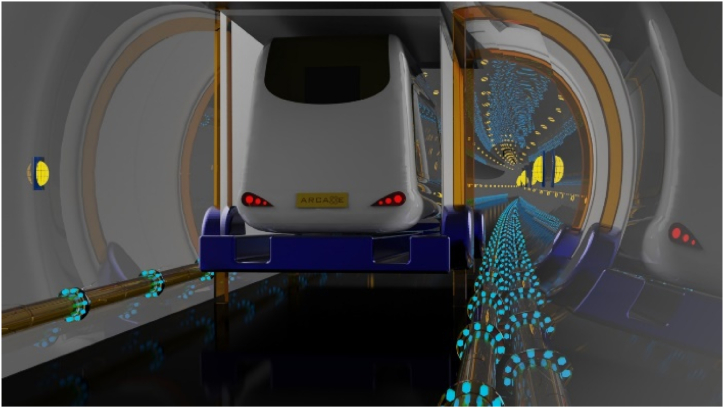
This project grew out of a study of suburban mobility systems; this issue is believed to be is closely related to economic development, social equity, and sustainability, which are factors of increasing importance that have become crucial to meet the needs of human activities. In recent years, there has been an increased awareness referred to the fact that we are headed toward a future in which available resources will be increasingly limited, so planners are faced with the challenge of developing new technologies that reduce the impact of human dominance on nature. The vehicular road transport sector turns out to be one of the issues on which the most attention is being focused in achieving positive change for the coming years, going to work on its major critical issues, such as pollution of urban centers with high population density, worsening of the quality of the citizens' breathable air, and heavy reliance on fossil fuels, the direct derivatives of which are used as fuels by a majority component of vehicles equipped with endothermic engines [13]. To these aspects of environmental importance are added other negative aspects given by the movement of people, to date mostly supported by private means of transportation. While the use of personal means of transportation has so far certainly represented the best solution from the point of view of personal freedom and displacement, in heavily urbanized cities it turns out to be a heavy handicap from the point of view of transportation efficiency, since the average number of vehicle occupants is well below their maximum capacity, leading to a significant waste of space that directly results in a significant worsening of traffic congestion conditions, resulting in an often very high number of accidents. Such a large number of vehicles, and the resulting transport congestion, is also a non-negligible aspect from the point of view of worsening air quality in the city. In the face of these considerations, the solution deemed most advantageous based on the analyses carried out was to create a shared vehicle, which takes advantage over long distances of magnetic levitation technology [2] combined with an induction charging system [15], within dedicated tunnels, making the system more efficient, since it will move individually, avoiding potentials accidents and without getting in the way of other vehicles that would delay its travel time. Assuming that the technologies and the basic idea chosen are still being tested and developed, the Arcade concept fits in as a viable alternative solution for the suburban mobility of the future, going to complement and potentially replace today's transportation, starting with cars, trains and buses, later this idea concept allows it to be taken up by going to expand the possibilities offered for longer-haul routes, being able to allow us to rethink the way we think about and use ships and planes today, thanks to the construction of underwater tunnels. The idea of the Arcade project was born with the conception of a product associated with a service, helping the user to manage it all through the app. The experience is designed so that the user books his or her route by indicating through the dedicated app the place of departure; after collecting travelers, the vehicle reaches the dedicated tunnels, which can be underground tunnels or outdoor semi-tunnels. In the former case, the vehicle positions itself on an elevator where the wheels move inside the body, enabling movement through magnetic levitation. Once the high-speed ride is over, the process of ascending is the same as descending. Finally, Arcade, following a more widespread route, takes users to the destination chosen when booking the trip.
Therefore, the main purpose of this study is to portray a view of a futuristic transportation vehicle and system by examining current mobility requirements and constraints according to the problematic existing nowadays. This will be presented by means of the application of the IDeS methodology (Fig. 1). This method is organized according to a well-defined analytical scale and is useful for designing a viable product on the market, quickly and very accurately. Industrial Structure Design (IDeS) was chosen to be used because this is a systematic design method that can uncover the customer's needs and the essential technical solutions to achieve a good innovative product. With this method, the foundation was laid for the development of a new hybrid vehicle, which combines the functions of an electric minibus with those of a maglev train, with the goal of reducing travel time over long distances, while also providing widespread service within the city. This method consists of combining and sequentially carrying out a series of steps proper to some well-studied and useful innovative design methodologies, the most important of which are Quality Function Deployment (QFD) and Stylistic Design Engineering (SDE). QFD analysis, which is fundamental for the initial stages of analysis, and design setup [10], turns out to be the most analytical method and consists of several steps, as seen in [Fig. 1], to be carried out in sequence and which allow one to go and get a clear view of the landscape in which the product will operate and then a quick and effective design setup. The SDE methodology, on the other hand, enters the field at the design stage, i.e., when, having carried out the initial analyses with the help of the QFD and defined the architecture of the product and service, one finds oneself shaping the product in the best and most coherent way possible. This scientific method turns out to have long been used in industry by well-known international design firms, and being born and developed in the internal corporate environment there is little literature from which to study it [7,8]. This involves the subdivision of various tasks carried out gradually by the design team, allowing them to arrive at a high-quality end result in a scientific and repeatable manner. The project presented here aims to reorganize the mobility network, which through this innovative design will provide a sustainable yet practical alternative to replace all highly polluting, inconvenient and slow transportation. The report is divided into sections that follow the structure of the IDeS method. The research started by studying different types of suburban vehicles, researching both qualitatively and quantitatively what their problems and strengths are. Through benchmarking, different alternatives were compared, arriving at the definition of features, technologies and innovations in product architecture. Going through the stylistic study, 2D tables, 3D modelling and rendering, the process ended with prototyping and a reflection on future developments.
Fig. 1.
IDeS base structure.
2. Materials and methods
The process of project development is based on the structure of industrial design and can be resumed in a road map (Fig. 2).
Fig. 2.
Project road map.
IDeS method is mainly organized in three main phases [7]:
-
1.
Project Setup.
-
2.
Product Development.
-
3.
Production Setup.
Designers and mechanical engineers are mostly involved in the first two phases, while production engineers are responsible for the third step. Furthermore, according to this methodology, producing workable design solutions necessitates precise design planning, which includes several instruments to judge the viability of these potential solutions. As a result, all the tools that were anticipated and included in the IDeS methodology's design approach were used. Only the first two stages of the approach were covered in this study, with the intention of creating an unproven, production-ready design idea. Consequently, the following design phases can be used to summarize the provided process:
-
1.
Describe: consists of an analysis of the environment, a market analysis and a statement of goals.
-
2.
Measure: includes the Quality Function Deployment.
-
3.
Analyze: are included Benchmarking, Top–Flop Analysis and the WHAT/HOW Relationship Matrix.
-
4.
Design: this category covers Product Architecture and Stylistic Design Engineering (SDE).
2.1. Project Setup
Project setup includes (a) Environment Analysis, (b) Market Analysis, (c) Benchmarking, (d) Product architecture and (e) Budget.
2.1.1. Environment Analysis
The environmental analysis aids the designer in comprehending the environment in which the new product must function in order to be appropriate for the target market.
2.1.2. Market analysis
During the market analysis phase, the designer determines the demands that the market has for the new product. This kind of study is created using the QFD, which stands for Quality Function Deployment. It starts with a detailed examination of the market and the competition and gives mechanical designers a better understanding of the demands and expectations of the client. In order to specify the project objectives, this is crucial. The Six Questions, the Matrix of Relationships of Relative Importance, and the Matrix of the Relations of Dependence/Independence serve as the foundation for QFD. The six questions are intended to provide a clearer picture of the context and, as a result, to develop a set of standards for product quality. They are the following: (a) Who is the product for? (b) What: What is the product's purpose? (c) Application: How is the item applied? (d) The product's usage location. (e) The product's usage period. (f) Why: What does it accomplish?
The major qualities that the product must have and which arose from the analysis carried out with the six questions are then placed on the rows and columns of a matrix, the Matrix of Relationships of Relative Importance, which is followed by interpolating the criteria. How much the requirements for the rows are more or less significant than the requirements for the columns may be one area of concern. Each cell is given a value between 0 and 2 depending on how significant each interpolation need is ranked: 0 if the row requirement is more crucial than the column requirement, 2 if the column requirement is seen to be more crucial, and 1 if both are important. The ranking of the needs, from the most significant, with the largest numerical value, towards the least important, is achieved once the values of every column are added together. In accordance with how dependent or independent the row need is in relation to the column requirement, each cell in the dependence/independence matrix is given the values 0, 1, 3, or 9: If the row requirement is totally independent of the column, the value is 0, 1, 3, and 9, respectively. If the row requirement is totally reliant on the column, the value is 0. This results in a ranking of criteria that are more reliant and less dependent.
2.1.3. Benchmarking
The Benchmarking is the phase in which the designer analyses his potential competitors on the market, comparing through a simple table the technical characteristics of different products, with the aim of fixing the upper limits of innovation of the new product. The table was structured according to the needs identified by the answers to the six questions. At the conclusion of each column, the quantity of the worst performance (Flop) and the best performance (Top) is added. The number of features that must be innovated among those listed in the Innovation Column is determined by calculating the quantitative difference between both the Tops and the Flops and using the highest score that may be attained. Finally, a chart was generated to better visualise the results obtained. After total number of characteristics that need to be innovated has been determined, it is essential to identify each one. In order to do this, one should take into account the What-How matrix, that harmonizes the findings of the Top-Flop Analysis with those of the connection matrices. The matrix has technical qualities taken into account from the examination of rivals' goods as columns and basic product needs discovered through relationship matrices as rows. Each cell is given a number that could be 0, 1, 3, or 9, depending on how much a feature influences a certain product/service attribute. This is important to fill all fields with a numerical value. The traits of the product that has to be developed may be calculated by adding the value calculated for each column.
2.1.4. Product architecture
The designer starts to define the aesthetic and functional aspects of his concept through product architecture. In order to get a general sense of the product's appearance and functioning, designers can use this approach to assign certain functions to the relevant physical component without becoming bogged down in specifics and technical intricacies. In order to provide a foundation upon which to build the complete system, it is possible to evaluate the harmony between the pieces and their roles via simplification of the result.
2.1.5. Budget
Cost estimates for design tasks may be obtained through budget planning. Budgeting is necessary to comprehend product expenses and project the product's potential selling price. When referring to the first phase of the IDeS method (Project Set-up and Product Development), the budget only refers to research and development costs. In the second portion, the budget is determined in relation to the design, prototyping, testing, development and redesign phases, specifying in each the costs of research, personnel hours, materials and equipment for the prototype. The total result is the budget required to realise a functional prototype. However, in this article, as already mentioned, only the budget for the Project Set-up and Design phase is considered.
2.1.6. Stylistic Design Engineering (SDE)
The SDE concludes the project setting phase; the main style trends are analyzed to define the general aesthetic features of the project: Retro, Natural, Stone and Advanced Style. Sketches of the different proposals are then made, followed by orthogonal projections of each one. Then, the best proposal is selected, and the 3D modelling is carried out. Finally, in the last step, the renderings are created using appropriate software.
Based on the sketches created, product archetypes were compared in order to identify the best one. CFD analysis was conducted for each drawing, to predict and anticipate the fluid-dynamic behaviour for each style. C.F.D. stands for Computational Fluid Dynamics, i.e., the set of techniques that make it possible to simulate fluid dynamics using computational systems. Computational Fluid Dynamics efficiently solves flow and thermodynamic problems in fluids: it calculates fluid properties (forces, pressures, velocities, temperatures, etc.) and provides access to knowledge of the phenomena through graphical representations and numerical values, simulating, according to a simplified model, the trajectories and behaviour of flows that hit a 3D model given an initial velocity. The most useful tools to compare the performance of objects with different shapes are the drag coefficient and the Venturi Effect. The air resistance for a certain form is determined by the drag coefficient, which is an adimensional number. It is calculated by dividing the drag force (Fd) by dynamic pressure, which equals 1/2 air density multiplied for the square of the speed v, by the reference area A of the form, and the drag force (Fd):
Using the drag coefficient makes it possible to calculate the actual drag force for any given speed or air density. Also, according to Venturi's Principle, as the fluid velocity in the throat is increased there is a consequential drop in pressure. Other essential factors considered in the CFD analysis of the models are lift and downforce, i.e. respectively the vertical force generated by the movement of the air which tends to lift the vehicle, reducing its stability at high speeds, and the aerodynamic force which pushes the vehicle towards the ground, increasing its grip.
2.2. Product Development
The operative stage of the project is called Product Development. Definition of the product's dimensions, components, and technology, as well as the creation of a digital model of the product, are the objectives of this part. Following that, the testing and prototype phase begins.
2.2.1. Design engineering
Design engineering primarily consists of two phases: in the first, utilizing 2D and 3D modelling software, the shape, size, and materials of the design are established. The second phase then begins, during which the parts and specifics may be established in order to comprehend how the product can be used.
2.2.2. Prototyping and rendering of product
This phase is critical since it is now that the design must be verified from a new perspective. Prototypes might be digital (created using CAD software), aesthetic (realized with rendering tools or 3D printing), functional (a 1:1 scale prototype), or virtual (using augmented reality). A product and associated service can be developed using any of these prototypes. In reality, testing the service interface is equally crucial, and this may be done with the use of applications for vector graphics (such as Adobe Illustrator) and user experience simulation (such as Adobe XD).
3. Case studies
3.1. Gantt plan
The Gantt plan is a horizontal bar chart used to illustrate the schedule of a project and related activities or events during its development, this defines activities and keeps the results under control. So before starting with the first stages of research, a Gantt plan is defined to plan the next three months (time taken to develop the project) and divide the work into different macro-phases:
-
a)
Environment analysis
-
b)
Market analysis
-
c)
Benchmarking
-
d)
Budgeting
-
e)
Architecture of the product
-
f)
Styling
-
g)
2D tables
-
h)
3D modelling
-
i)
CFD analysis
-
j)
Renderings
-
k)
Prototyping
3.2. Environment Analysis
For the development of the Environment Analysis, the means of extra-urban mobility most used by the Italian population in the period preceding the Covid-19 pandemic were taken into consideration. According to Anfia, 79.9% of the population travels by car or motorbike, 11.6% by bus, tram and metro, 5.8% by train, 2.8% by air and 0.4% by sea (Fig. 3). Statistical data on environmental pollution were subsequently compared, in particular the percentages of total greenhouse gas emissions in the European Union, which correspond to 19.35% for road transport, 3.77% for aviation, 3.61% for shipping and 0.4% for transport on rail networks (Fig. 4); these data were then also compared with those of 1990, highlighting the significant increase they have undergone; for road and rail transport this corresponds to +19.2%, for aviation +128.9% and for shipping +31.7% (Fig. 5). This preliminary analysis is followed by a more detailed one for each means of transport: the percentages relating to pollution and passenger transport, the development of technologies, the issues most suffered by users were considered, and various case studies were also identified.
Fig. 3.
Total Italian passenger traffic (Anfia, 2019).
Fig. 4.
Transportation issue in 2017.
Fig. 5.
Evolution of greenhouse gas emissions by sector.
3.2.1. Aircraft and navigation means
The first vehicles studied were aircraft and navigation vehicles to obtain a comprehensive scenario of all urban and suburban mobility systems. All these vehicles were analyzed by comparing operation, usage characteristics, usage scenarios, user type, environmental impact statistics, strengths and weaknesses, comparing different case studies and developing QFD analyses with relative importance and interrelationship matrices. The problems found in these vehicles were found to be common to those of the vehicles analyzed later and of great interest, so the main objective of the project was to solve those of greatest relevance to our case study.
3.2.2. Trains
According to the statistical data of ISTAT, to date the means of rail transport are the cause of the production of fine dust from 800 to 1300 tons per year, highly polluting. However, it is also true that these vehicles use more than 30% sustainable sources. To date, about 5,699,000 people take regional trains and subway lines daily in Italy [16]. In the 1800s the steam locomotive was born, used until 1920 when the first electrified lines began to be used, in 1950 the first diesel trains were born, in 1969 the first patent for magnetic levitation trains was issued. In 1969 the first patent was issued for magnetic levitation trains, today present mainly in Japan and the goal set for 2050 is to make trains carbon neutral [17]. The problems in the travel experience observed by the user are linked to the crowdedness of the trains and the dirtiness of the environment, two problems that are even more evident because of the pandemic situation, frequent delays and long travel times.
Then, three case studies were noted:
-
•
Goldenpass Express: a panoramic train, whose redesign was entrusted to Pininfarina, who has decided to keep a large window that gives travelers a frontal view with great effect, avoiding any reflection or glare on the photos taken by passengers.
-
•
Hyperloop: a project by Elon Musk, characterized by train capsules that move in a system of frictionless tubes with very low magnetic pressure, which allows them to reach very high speeds with extremely low fuel consumption [14].
-
•
Commute 2030: a simple, ergonomic project designed to improve the travel experience by dividing the train experience into different types of wagons where you can travel, work, eat and relax.
Finally, the six-question method was used:
-
1)
Who uses them? This transportation means can be used by people of all ages, from students who need to get to schools and universities, to workers who need to travel to work, but also by young people, adults or families to reach places of interest. Requirements obtained after the discussion: cheap, capacious, quiet, ergonomic.
-
2)
When are they used? Students and workers use it on a daily routine, with a greater affluence in the daytime and afternoon hours. For others it can be used for leisure weekends, to visit new places, as an alternative to the car according to timetables. Requirements obtained after the discussion: clean, maintained, on time.
-
3)
Why are they used? This type of vehicle is used to reach places of interest more quickly and easily, avoiding traffic delays or possible accidents, but also providing pollution and spending less. Requirements obtained after the discussion: practical, safe, fast.
-
4)
What are they used for? Trains accommodate large numbers of people, traveling medium and long distances, moving faster than a r or bus. Requirements obtained after the discussion: fast, capacious, multi-place.
-
5)
How do users use them? It is used as a means of suburban transport, where passengers enjoy the long journey while sitting, so they can relax, read, listen to music, study or work. For shorter journeys one can also travel standing up. In addition, travellers can travel alone or in company. Requirements obtained after the discussion: digitalized, comfortable, controlled, aesthetic.
-
6)
Where do they use them? It is used to travel between different cities, moving on predetermined routes on rails, thereby saving time and consuming less. Requirements obtained after the discussion: environmentally friendly, comfortable, connected.
The requirements were then placed into the relative importance matrix (Fig. 6), from which we get the most important features a train should have: safety, digitization, multi-place, ergonomics, and dimensions.
Fig. 6.
Relative importance matrix.
Then built, the interrelationship matrix (Fig. 7), the most independent requirements turn out to be dimensions and maintenance, while the most independent ones are comfort and practicality.
Fig. 7.
Interrelationship matrix.
3.2.3. Bus
Statistical data show that public transport is responsible for 3% of CO2 emissions. Taking seventeen European countries into account, Italy is at the bottom of the league to produce new zero-emission buses [5], with only 5.4%. 12% of the population regularly use public transport, including buses. In 1821, buses used steam technology, but switched to internal combustion engines in 1897. In 1970, the first hybrid electric-powered buses were introduced and in 2009 the first patent for a hydrogen-powered bus was issued, which is still under development [12]. Regarding the travel experience, the problems observed by the user relate to long delays over long distances, also due to traffic (another problem), and tight spaces and lack of movement.
The three case studies were examined again:
-
•
Muji Gacha: the first all-weather autonomous bus, designed without a specific front or rear end, with a band of LED light surrounding the bus, acting as both headlights and a screen informing passengers of their movements and destination [9].
-
•
Next: a 3-m-long, detachable, automatic, zero-emission (electric) bus train made up of fast carriages which, like magnets, can be attached in motion when they are on the same route. As they align, the doors open, the compartments become interconnected, and the vehicle becomes one.
-
•
Future Bus: a bus of the future, designed by Elon Musk, which is extremely fast and environmentally friendly, and designed to travel in small tunnels. This solution could eliminate car traffic in large cities and enable fast (and emission-free) movement of bicycles and pedestrians. And pedestrians.
In the same way as for trains, the six-question method was used:
-
1)
Who uses them? Students, workers, families, young people, adults and seniors.
-
2)
When do they use them? Many times a week, even more than once a day in the case of commuters.
-
3)
Why do they use them? To travel to nearby or distant cities, to study or work.
-
4)
What are they used for? They are used to transport many passengers, ensuring more connections between and within cities.
-
5)
How do users use them? For short or long journeys, sitting or standing, alone or in company.
-
6)
Where do they use them? Between and within cities and towns.
Finally, the six questions were evaluated according to the following requirements: ergonomic, economical, quiet, spacious, clean, serviced, punctual, practical, safe, functional, spacious, multi-position, autonomous, digitised, comfortable, stylish, comfortable, fast, connected and ecological. By entering the requirements in the relative importance matrix (Fig. 8), the most important characteristics that public transport should have can be obtained: digitalisation, comfort, functionality, convenience and safety.
Fig. 8.
Relative importance matrix.
From the interrelationship matrix (Fig. 9), the most independent requirements are functionality and ergonomics, while the most dependent requirements are comfort and safety.
Fig. 9.
Interrelationship matrix.
3.3. Benchmarking
As far as the benchmarking, attention has been focused on only two of the four means taken into analysis, which are useful for the development of the project: trains and buses.
3.3.1. Trains
In the case of trains, the most used Italian trains were considered, as well as those best known in the world for innovation. To the first category belong: Trenitalia's Frecciarossa, the fastest train in our country that guarantees fast and frequent connections, Italo train, with fewer stages than the previous one, which guarantees comfort and safety, and Minuetto, also owned to Trenitalia, born at the beginning of 2000, which travels on suburban, regional and interurban routes. The second category includes the Shanghai Transrapid, a German monorail train with magnetic levitation, the Maglev, which travels without touching the rails by means of magnetic levitation, and the Shinkansen, a bullet train of the Japanese railway network. For the development of the benchmarking table (Fig. 10), the following were considered: the origin, length and width of the train, to understand what were the proportions used, the number of wagons, technology (diesel, electric or magnetic levitation), CO2 emissions, to understand how much each of the analyzed trains has a bad impact on the environment, the power, the maximum speed that the train can reach, the passenger capacity, and the cost of the ticket. Data on the characteristics and performance of the selected trains in both Italian and international territory were searched on the official websites of the relevant infrastructure. On the other hand, in the case of maglev, since this uses different technologies, the search was more complex; therefore, data from sources directly related to the infrastructure or the company operating its services were not used. These data, in fact, were found within studies comparing the technology of high-speed trains currently in use with the evolving technology of maglev trains [18].
Fig. 10.
Benchmarking.
By comparing the best and worst qualities of each type of transport, the best (top) and worst (flop) characteristics were highlighted, the difference calculated for each vehicle and the best and worst in general were identified (Fig. 10). Reading on the lines of the benchmarking table, it has been possible to define an ideal train: it should have a length of more than 202 m and a width of more than 3.5 m, at least 11 wagons, travel by magnetic levitation, not emit CO2, have a power of more than 9800 kW, a speed of more than 431 km/h and a low to medium ticket cost. The best score determines the bare minimum of characteristics that must be novel in the design; in our instance, that number is four.
Finally, a what-how matrix (Fig. 11) was constructed to compare the results obtained from the relative importance matrix with the product innovation characteristics. The length, technology, and capacity needs are highlighted in this matrix as those that demand the greatest innovation.
Fig. 11.
What-how matrix.
3.3.2. Autobus
Regarding buses, the most popular buses used in various countries around the world were considered and compared. The Van Hool Astromega, a double-decker bus, which guarantees a comfortable journey thanks to the installed audio and video devices; the Iveco Crossway, designed for interurban and school transport; the Setra TopClass 500, known especially for its elegance; the Greyhound Express, which belongs to the largest bus service in North America; and finally, the Volvo 9900, a comfortable, safe and elegant bus, recognisable even from a distance. Once again, several relevant characteristics were included in the benchmarking table (Fig. 12): origin, height and length, technology used (petrol, diesel or electric), CO2 emissions, power, maximum speed, passenger and baggage capacity and ticket price. Data on the characteristics and performance of selected autobus were searched on the related catalogs provided by the manufacturing companies.
Fig. 12.
Benchmarking.
This table shows that the ideal bus should have a height of more than 4 m, a length of more than 14 m, be electrically powered, reduce CO2 emissions by more than 95%, have a power of 530 HP, a speed of more than 160 km/h, a capacity of 83 passengers and 13.9 m2 of luggage space. The minimal number of characteristics that must be enhanced in the project, in this instance three, is determined by the score for the best bus. (Fig. 12).
For buses with Δ ≥ 4, a what-how matrix (Fig. 13) was set up to compare the results obtained from the relative importance matrix with the product innovation characteristics, which show the requirements that need to be most innovated: size, technology and capacity. The results turned out to be the same as for the analysis on trains.
Fig. 13.
What-how matrix.
4. Arcade
4.1. Budget: research costs
Having planned the overall project development time, spread over three years, a research and development cost analysis was carried out for the development of the project, estimating the costs relating to: performance, equipment, and prototyping (Fig. 14). The following were included in the evaluation of performance costs: analysis (market and competition), architecture and styling, design and prototyping, experimentation, map and re-design, re-prototyping, experimentation, and deliberation-Reference prototype. Several engineers, designers and workers were assigned to each phase, with hourly fees of 50.00€, 40.00€ and 30.00€ respectively. Added to the vehicle service costs are the equipment costs, which, aimed at the realization of the first prototype, are obtained from the cost of each material added to the cost of the necessary processing, while the costs of implementing the technologies are estimated on the basis of the expected costs of developing vehicles that exploit the same technologies [11].
Fig. 14.
Budget.
Then, the cost of the infrastructure and the years of development were assumed. Regarding costs, the average rail cost per kilometre (tunnel) was considered, which is about 44 million €, multiplied by the length of the Italian motorway network, equal to 6965.40 km, for a total of 306.477 billion € [18]. The line on which Arcade will travel will run under the Italian motorway network; therefore, assuming an advancement of 0.550 km per day, it has been estimated that the time needed to complete the infrastructure will be 35 years.
4.2. Cost-benefit analysis
Any large project needs a cost-benefit analysis to increase its validity, to understand how advantageous or disadvantageous it is to implement it. Cost-benefit analysis (CBA) (Fig. 15) is a systematic approach used in economics and engineering to make project evaluations based on measuring and comparing all directly and indirectly related costs and benefits. The current costs of the Italian state due to the mobility sector were explored: accidents, metro, road and rail maintenance, strategic infrastructure, and pollution. The introduction of Arcade, hypothetically in 2060, will result in a drastic reduction in the use of all current means of suburban transportation: flights and cars may be reduced by 50%, buses by 60%, and trains by 80%. It is estimated that this may lead not only to reduced costs, but also to lower CO2 emissions, reduced particulate matter production, faster travel times, and reduced traffic congestion and accidents [4,6].
Fig. 15.
Quantitative chart.
4.3. Architecture product
As a result of the research carried out in the analysis described above, it was observed that the main problems in current suburban vehicles are: narrow and uncomfortable seats, long journey time, tedious waiting, the presence of traffic for road vehicles and often adverse weather conditions, which do not allow normal mobility. In addition, the characteristics resulting from the matrices that the vehicle must possess are: aerodynamics, digitalisation, stability, comfort and safety. Thanks to these elements, a product architecture has been defined that incorporates these aspects in the best possible way. The project involves the construction of a hybrid vehicle, capable of moving through underground tunnels at high speed (we have assumed 500 km/h), through a system of magnetic levitation; once it arrives in the destination city, it is then placed on lifts designed so that the vehicle can safely take off its hidden wheels and move along the road using the electric motor. The main innovation lies in the method of recharging the motor, which is done by induction charging, active throughout the underground journey. The basic idea behind the project stems from the realization of the advantages of traveling in underground tunnels. First, greater safety is ensured, since the vehicle is protected from atmospheric agents, road accidents are prevented and the vehicle itself requires less maintenance; moreover, the presence of traffic is avoided and there is the possibility of traveling along more linear routes, which has the benefit of reducing travel times (Fig. 16).
Fig. 16.
Circle of requirements.
4.3.1. Magnetic levitation
The main reason for choosing a magnetic levitation system is the considerable reduction in the environmental impact of this technology. One of the main countries developing this new transport system is Japan, with models such as the Maglev, described above. In detail, magnetic levitation is that force which can suspend a subject above another object without the aid of other forces and is able to counteract the force of gravity. There are many methods of conceiving levitation, and the theory arose because of the considerations of Earnshaw's Theorem, according to which a collection of point charges cannot be maintained in a configuration of stable equilibrium simply with the aid of the electrostatic interaction of the charges. This means that in order to achieve and maintain equilibrium, the interaction must be between multiple forces, i.e. electrical, gravitational and magnetic, or combinations of these. Although magnetic levitation trains use only magnetic force for locomotion, they exploit the combination of this force with electromechanical force. There are two types of magnetic levitation:
-
•
Electromagnetic suspension (EMS): uses electromagnets installed on the end of a pair of structures underneath the train that wrap around the sides and bottom of the guideway. The magnets, attracted to the iron-rolled rails, support the train (Fig. 17).
-
•
Electrodynamic Suspension (EDS): the train achieves levitation by exploiting the opposite polarities of the vehicle's supercooled and superconducting magnets (Fig. 18).
Fig. 17.
Electromagnetic suspension.
Fig. 18.
Electrodynamic suspension.
The repulsive force develops as a result of the movement of the vehicle and is not active when the vehicle is stationary. Comparing the two choices, the first case is more unstable and requires more energy but is more economical; the second case is more stable and saves energy, but is more expensive. Of the two choices, the one that seemed most suitable for the project in question is the second, which meets the safety and stability requirements.
4.3.2. Electric motor
The vehicle will be equipped with an efficient and sustainable electric motor. An electric motor is a special rotating electrical machine, but not exclusively, which converts incoming electrical energy, applied to the supply terminals, into outgoing mechanical energy made available on the motor axis. This type of electrical machine is based, as in the case of the electric generator, on the electromagnetic forces that interact between a system of currents and a generator. Thanks to its innovative features, the electric motor is environmentally friendly, quiet and compact, requires little maintenance, provides high short-term performance and greater stability. Despite this, there are still problems relating to weight, battery disposal and recharging times. Regarding this last point, as we shall see in the next paragraph, a solution has been devised which is partly intended to resolve the problem.
4.3.3. Induction charging
As mentioned above, one of the current problems with vehicles equipped with an electric motor is the long recharging times. To avoid this problem, the proposed solution is based on constant induction recharging throughout the journey through the underground tunnels. The idea is to combine induction and magnetic levitation to transfer electrical energy to the vehicle [15] so that charging on the surface is avoided, times are significantly reduced, and performance is increased. A receiver (receiving coil) is placed at the bottom of the vehicle, while several coils are inserted into the road surface to act as transmitters. By using current, the coils produce a magnetic field which enables the coil on the vehicle to receive it and convert it into electrical energy (Fig. 19).
Fig. 19.
Electric charge.
4.3.4. Autonomous driving
The automotive market is moving more and more towards the introduction of autonomous driving systems with the aim of significantly reducing the percentage of road accidents due to the higher level of attention to driving guaranteed by artificial intelligence. The following rationale meets the requirements derived from the research phase and is optimally suited to the vision of a futuristic vehicle [3]. Autonomous driving is defined as a vehicle that combines the main transport capabilities of a traditional car with the potential to detect the environment and navigation without direct human intervention. SAE International Automotive has identified 6 levels of autonomy (from Level 0 to Level 5): Level 0 (No Driving Automation) - Most modern motor vehicles are Level 0: manually operated. The “dynamic driving task” is carried out by the driver despite the possibility of assistance devices. Using the emergency braking system as an example, automation is technically not possible because it does not “steer” the car. “Driver Assistance” is the name given to the lowest level of automation. One autonomous driving assistance system in the car can steer or accelerate (cruise control). A feature of adaptive cruise control, which is part of level 1 automation, keeps a safe distance between the vehicle in front of it while the human driver concentrates on steering and braking. ADAS, or advanced driver assistance systems, are referred to as Level 2 (Partial Driving Automation). Both steering and accelerating and decelerating may be controlled by the vehicle. This automation is not self-driving because a person is still in the driver's seat and has the option to take over at any time. Level 3 (Conditional Driving Automation) - From a technology standpoint, there is a significant increase from Level 2 to Level 3, but from a human perspective, the change is minimal, if not nonexistent. Level 3 cars are equipped with “environmental sensing” skills and are capable of autonomously making judgments, like as accelerating past a stationary object. But a human override is still necessary. If the system is unable to complete the mission, the driver must be awake and prepared to take over. Level 4 (High Driving Automation) - The main distinction between Level 3 and Level 4 automation is the ability of Level 4 vehicles to act in the event of a problem or system breakdown. Usually, these cars don't need to interact with people in this way. Yet, a person may still manually override. At Level 4, vehicles are capable of self-propulsion. Yet because the regulations and infrastructure are the same, they can only do it in a small area (usually an urban environment where top speeds reach an average of 30mph). It is known as geofencing. Today's Level 4 vehicles are mostly built with ridesharing in mind. Level 5 (Full Driving Automation) – Vehicles at this level do not need a driver to pay attention because the “dynamic driving task” has been taken care of [1]. Level 5 cars won't even have steering wheels or pedals for braking and acceleration. They will be able to go wherever, be unfettered by geofencing, and do any duty that a qualified human driver can. There are testing completely autonomous cars in a number of places throughout the world, but none are yet accessible to the general public. Arcade, when it moves on the road, is in the last level, as no driver intervention is required. These systems use a Cognitive Rail Pilot, i.e. a system of cameras and radar that provides greater safety for the passenger (Fig. 20).
Fig. 20.
Automation levels.
4.3.5. Dimensions and interior
The development of the vehicle then moved on to the study of the overall dimensions, trying to define the interior layout in a rational manner. First of all, the effective dimensions of the vehicle were established; to make this possible, the vehicles present on the market were considered, i.e. cars (in particular city cars), minibuses and buses. From this initial analysis, the following dimensions were considered appropriate for our vehicle: the length of two city cars for a total of 7000 mm and the height of a bus, equal to 3000 mm, for a total capacity of a maximum of 8 passengers. To ensure the comfort and ergonomics of the individual passengers, the seats have been arranged so as to leave just the right amount of space for each person to walk and move, allowing them to travel comfortably both individually and in company. Each seat is equipped with a 360° swivel system, which allows you to swivel in the most appropriate direction.
4.3.6. VR headset
In order to make the journey less boring and to obviate the sense of claustrophobia that some passengers might feel while traveling in the tunnels, several solutions to entertain and distract the user were evaluated: televisions (already available currently in trains and buses), tablets, and headphones. While these instruments are for individual use, they could be disruptive to other passengers because of the overlapping sounds. In addition, even when headphones are used, there is not total isolation from the outside environment, so the most immersive turned out to be VR technology; through the integration of a visor and headset inside the armrest, connected by a cable as an anti-theft device, the passenger will be able to individually choose what most relaxes or entertains them.
4.3.7. App
An application has also been designed to facilitate the booking and purchase of the trip for the user. Geolocation will allow the user to select the address of the place where he needs to be picked up from the vehicle and, consequently, the address of the place of destination, choosing the most convenient solution from among the possible solutions, thanks to the display of the vehicle's performance and available seats on board. At the end, the booking is concluded with the payment of the ticket through an electronic payment (Fig. 21).
Fig. 21.
App.
4.3.8. The logo
The name “Arcade” was born with a double meaning: 1. Arcade literally translated from English means “tunnel”, therefore, referring in our case, precisely to the system in which the designed high-speed vehicle moves; 2. Arcade is also referred to a type of early video games, therefore in this case it is associated with the presence of VR Headsets in the armrest of each seat that make the travel experience customisable, fun and interactive. It is from these two meanings associated with the word “arcade” that our logo was born, combining the stylised image of an arcade with a joystick's directional buttons (Fig. 22).
Fig. 22.
Logo.
4.4. Stylistic Design Engineering (SDE)
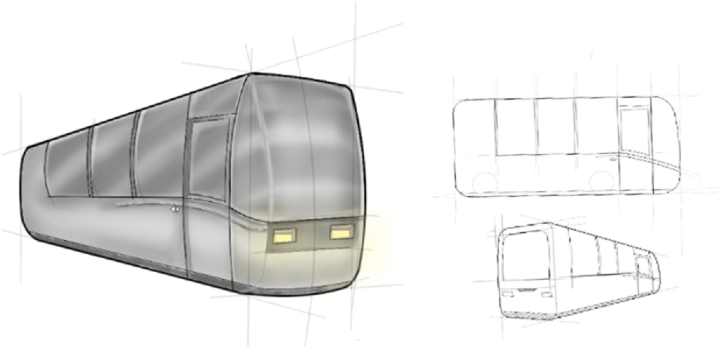
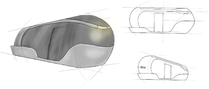
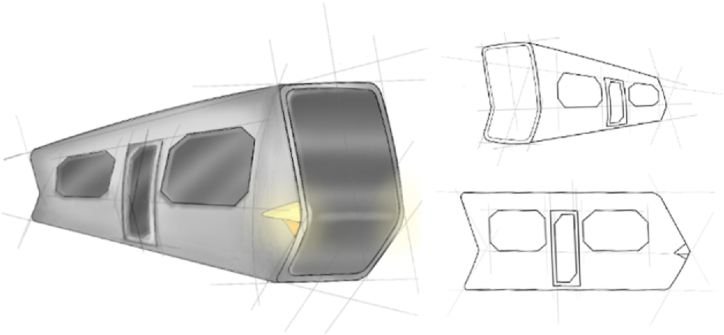
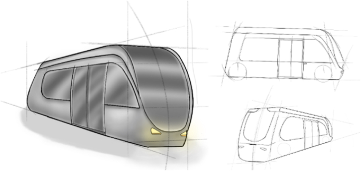
Several sketches were made, each for a different style: retro, which recalls more classic buses (Fig. 23); natural, distinguished by curved yet solid lines (Fig. 24); stone, based on the exaggeration of lines, straight and broken (Fig. 25); and finally advanced, characterized by lines that give a futuristic look (Fig. 26).
Fig. 23.
Retro style.
Fig. 24.
Natural style.
Fig. 25.
Stone style.
Fig. 26.
Advanced style.
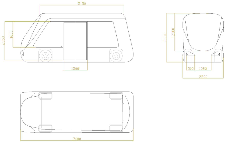
Subsequently, for each proposal first presented through the sketches, the technical drawings were made with the respective dimensions in order to compare the overall dimensions as well as the aesthetic characteristics. From the comparison and evaluation of the spaces available in each proposal, the most comfortable was found to be the Advanced Style (Fig. 28).
Fig. 28.
Advanced style.
4.5. Numerical design analysis (CFD)
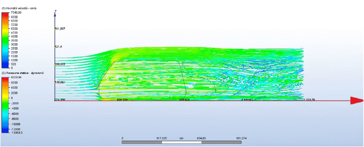
Therefore, the fluid dynamic analysis of each model was carried out. Regarding the Retro Style it can be observed that the frontal surface, which is perpendicular to the flow, generates a zone of low velocity and high pressure that produces a relative resistance (drag), conveying the flows towards the external surfaces and upwards, hence accelerating them. Looking at the upper flow pattern, there is a low-pressure zone on the top of the vehicle (indicated by an orange flow). This leads to a negative lift effect in accordance with the lift principle explained above. The back, on the other hand, due to the sudden cut of the surface generates a significant volume of turbulence (marked by the dark blue lines), as the air seems to be pulled in from the back. This results in a mechanical loss of energy. In the Natural Style, which was found to be the best, unlike the Retro Style, the acceleration of the fluid on the front has a gradual variation due to the more rounded shape of the surface; therefore, the resistance and pressure of the fluid are lower. From the pressure of the flow on the top, it can be assumed that the vehicle is exposed to neither lift nor downforce, resulting in neutrality. Turbulence generated at the rear is also less severe, as it tends to flatten out. The Stone Style is the best for the front surface, since the more pointed shape makes the acceleration of the fluid gradual, the intensity of the flows better, and in general the flows are homogeneous. The same is not so for the back, where a vacuum zone is created in which the area of external flows is pulled inwards. This results in a high volume of turbulence, especially in the upper corner, which makes the vehicle unstable. Finally, in the Advanced Style (Fig. 27) on the front the pressure intensity and flow velocity are reduced and more stable, giving greater aerodynamic stability. However, turbulence is generated at the back, which can be balanced by optimizing the track by reducing the speed of the vehicle on bends and increasing it on straight stretches.
Fig. 27.
Advanced CFD analysis.
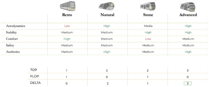
Based on these considerations, these data were compared with others in a benchmarking table (Fig. 29) to select the best proposal. The features examined were chosen based on the results gained from train and bus matrices: aerodynamics, stability, comfort, safety and aesthetics, and each was evaluated (low, medium, high). This style has good aerodynamics, as seen in the CFD analysis, which affects its stability especially when traveling using magnetic levitation technology. Mid-level comfort as it is not the most spacious among the four; mid-level safety since due to its small size it will have to have a slight deceleration when cornering. Finally, its aesthetics was rated as high because it was considered the most adaptable to the idea of future vehicles.
Fig. 29.
Top-flop table.
4.6. Interior design
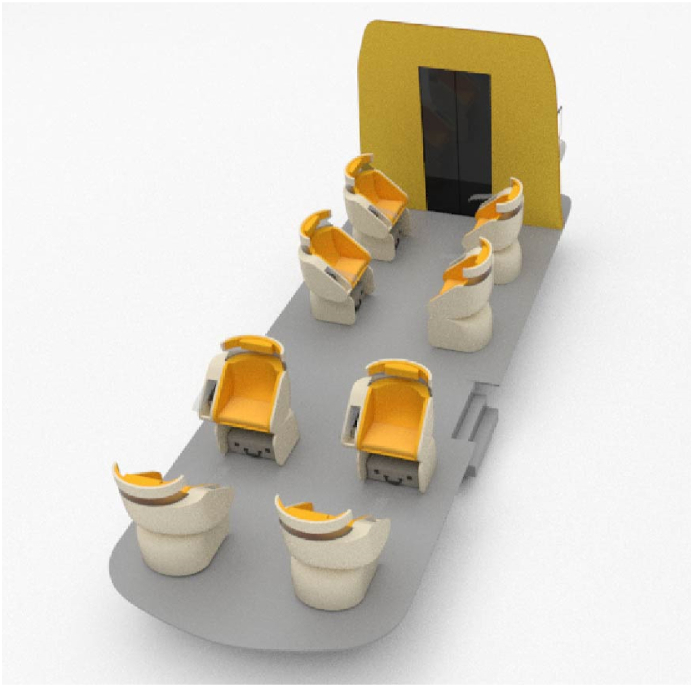
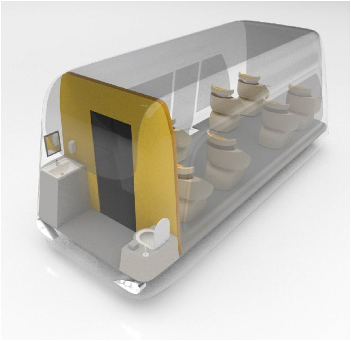
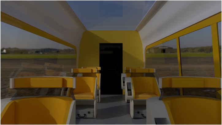
Demonstrating the high comfort of the proposed Advanced model, based on the established dimensions, an additional study was made on the vehicle's interior. First, eight single-seat seats have been arranged to ensure that each passenger has personal space, while still allowing him or her to converse with other travelers by simply rotating the seat up to 180° (Fig. 30). The seat and back have been designed wider (600 mm) than the conventional dimensions, equipped at the bottom with a spacious compartment in which to store one's luggage. Again, each seat has its own visor stored in the space on the right; this choice is a solution to a possible sense of claustrophobia for some passengers, over long distances. Finally, the vehicle at the back is also equipped with toilet, which takes up more space than the minimum dimensions required by norms (Fig. 31). Thanks to these solutions, Arcade has interiors that are not only comfortable but also versatile and complete with all passenger facilities (Fig. 32).
Fig. 30.
Seats rotation.
Fig. 31.
Toilet.
Fig. 32.
Interior design.
4.7. Prototyping and product rendering
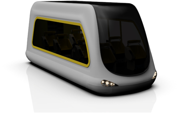
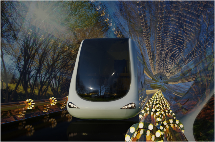
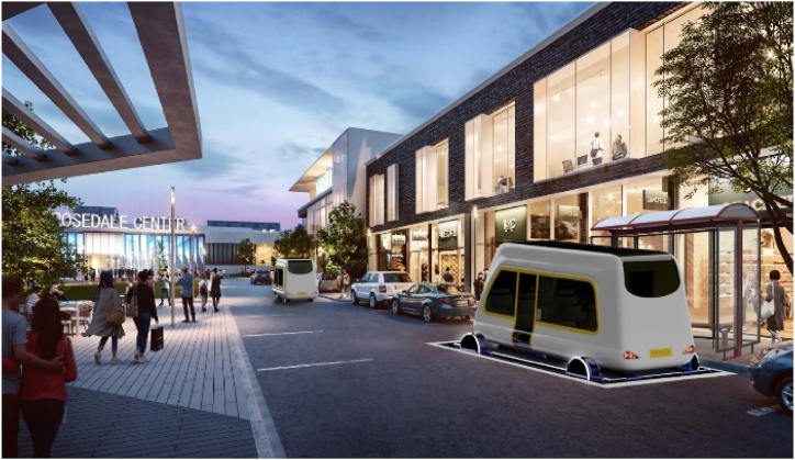
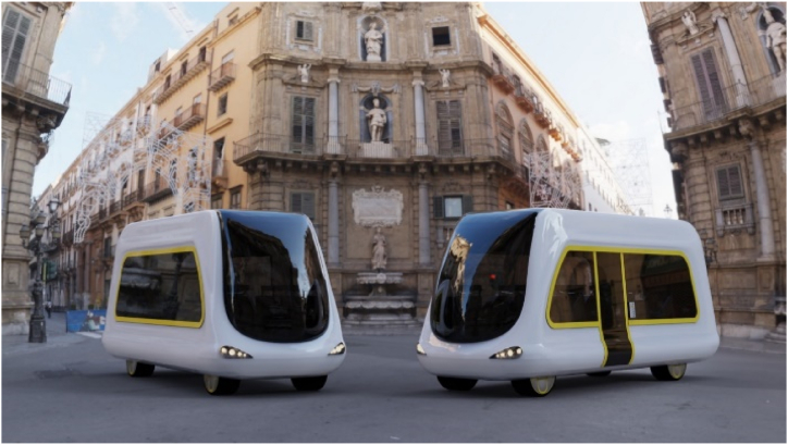
For the solid modelling of Arcade, Rhinoceros 7, a CAD software for 3D freeform surface modelling, was used. Generally, Rhino is used for industrial design, architecture, naval, jewellery, automotive, CAD/CAM and rapid prototyping. The three-dimensional model obtained was then rendered on Keyshot 9, software that allows 3D renderings to be created in real time (Fig. 33, Fig. 34, Fig. 35, Fig. 36, Fig. 37).
Fig. 33.
Arcade model.
Fig. 34.
Arcade in an outdoor tunnel.
Fig. 35.
Arcade on elevator goes up the street.
Fig. 36.
Arcade goes up on the street.
Fig. 37.
Arcade on the street.
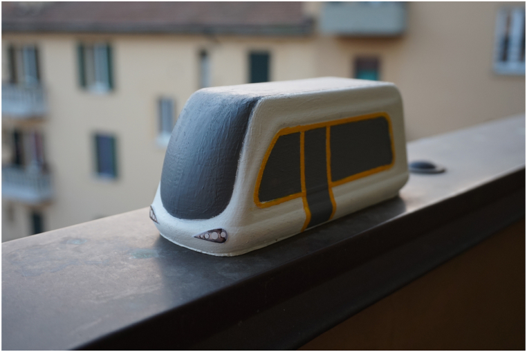
Finally, to verify the design model, a 1:24 scale three-dimensional prototype was made using additive manufacturing (Fig. 38).
Fig. 38.
3D printing.
4.8. Discussion
The creation of this case study demonstrated the value of the IDeS methodology along with the other two crucial tools employed, such as QFD and SDE, highlighting how the direct application of design and engineering application areas, in both areas, allowed the information flow to the organization to be better organized, beginning with the product design area. The IDeS method thus ensures that both technical and stylistic objectives are met with a consequent reduction in time and resources, in order to obtain a design concept ready for prototyping and eventually for launch to production. From the What-How Matrix for trains and buses it resulted that the three features to innovate were: length, technology, passenger capacity. Although Arcade has a short length and consequent passenger capacity, however, the cutting-edge technologies chosen for the futuristic development of this means of extra-urban mobility enable agile and rapid travel by allowing more units available for users. Comparison with vehicles currently in use showed that from the perspective of reducing CO2 emissions and air pollution, an electric power supply should be chosen rather than fuel-based; in addition, assuming future development of Arcade at least in 2050, magnetic levitation technologies were envisioned to be exploited. However, the huge costs and impact of developing the infrastructure in which the vehicles will have to move are evident; by the way, the use of these vehicles in the long run may compensate for the toll paid during construction.
4.9. Conclusions
Arcade is a concept project that aims to start a revolution in automation applied to means of transportation for daily use, which is not yet possible at the moment, but in the future, when technologies allow, could replace a significant component of all other means, providing efficient, widespread, safe and low-pollution transportation. In pursuing this goal, strong consideration was also given to the design of the vehicle's interior space, going to revolutionize current standards to provide the greatest possible efficiency for future autonomous mobility. As mentioned at the beginning of the report, this project is developed according to the IDeS method, It allows both specialist and non-specialized designers to swiftly, simply, and methodically implement a new design. The IDES techniques enable the creation of a complete product layout, comprising managerial, technical, and aesthetic aspects. This method turns out to be the most complete for the design and development of an entire industrial project. At the end of all the analysis done and through the use of the IDeS method, a project was obtained that responds to all the objectives set.
Arcade is therefore:
-
-
Autonomous, to avoid any driver distractions.
-
-
Ecological, as thanks to magnetic levitation and the electric motor, it does not impact on the environment like combustion vehicles.
-
-
Fast, traveling long distances in a short time.
-
-
Comfortable, designed so every passenger has their own space.
-
-
Safe, because moving on protected routes (tunnels) ensures smooth travel by avoiding accidents.
Author contribution statement
Leonardo Frizziero: Conceived and designed the experiments.
Giulio Galiè; Christian Leon-Cardenas: Analyzed and interpreted the data; Contributed reagents, materials, analysis tools or data; Wrote the paper.
Marella De Santis; Maria Sabrina Losito; Angela Tomaiuolo: Performed the experiments; Contributed reagents, materials, analysis tools or data; Wrote the paper.
Funding statement
This research did not receive any specific grant from funding agencies in the public, commercial, or not-for-profit sectors.
Data availability statement
No data was used for the research described in the article.
Declaration of interest's statement
The authors declare that they have no known competing financial interests or personal relationships that could have appeared to influence the work reported in this paper.
Contributor Information
Leonardo Frizziero, Email: leonardo.frizziero@unibo.it.
Giulio Galiè, Email: giulio.galie2@unibo.it.
Christian Leon-Cardenas, Email: christian.leon2@unibo.it.
Marella De Santis, Email: marella.desantis@studio.unibo.it.
Maria Sabrina Losito, Email: mariasabrina.losito@studio.unibo.it.
Angela Tomaiuolo, Email: angela.tomaiuolo2@studio.unibo.it.
References
- 1.Ahmed Khan M., Sayed H.E.L., Malik S., Zia T., Khan J., Alkaabi N., Ignatious H., El Sayed H. Level-5 autonomous driving—are we there yet? A review of research literature. ACM Comput. Surv. 2022;55(2):1–38. doi: 10.1145/3485767. [DOI] [Google Scholar]
- 2.Barbosa F.C. 2019. High Speed Intercity and Urban Passenger Transport Maglev Train Technology Review: A Technical and Operational Assessment. 2019 Joint Rail Conference. JRC 2019. [DOI] [Google Scholar]
- 3.Brenner W., Herrmann A. An overview of technology, benefits and impact of automated and autonomous driving on the automotive industry. Digital Marketplaces Unleashed. 2018:427–442. doi: 10.1007/978-3-662-49275-8_39. [DOI] [Google Scholar]
- 4.Danielis R., Chiabai A. Estimating the cost of air pollution from road transport in Italy. Transport. Res. Transport Environ. 1998;3(4):249–258. doi: 10.1016/S1361-9209(98)00004-2. [DOI] [Google Scholar]
- 5.Deliali A., Chhan D., Oliver J., Sayess R., Godri Pollitt K.J., Christofa E. 2020. Transitioning to Zero-Emission Bus Fleets: State of Practice of Implementations in the United States; pp. 164–191. 1800132, 41(2) [DOI] [Google Scholar]
- 6.Elvik R. How much do road accidents cost the national economy? Accid. Anal. Prev. 2000;32(6):849–851. doi: 10.1016/S0001-4575(00)00015-4. [DOI] [PubMed] [Google Scholar]
- 7.Frizziero L., Donnici G., Galiè G., Pala G., Pilla M., Zamagna E. QFD and SDE methods applied to autonomous minibus redesign and an innovative mobile charging system (MBS) Inventions. 2022;8(1):1. doi: 10.3390/INVENTIONS8010001. [DOI] [Google Scholar]
- 8.Frizziero L., Galiè G., Aldrovandi M., Franco S., Rana E. Design of an autonomous, sustainable sharing mobility solution aimed to mobility-disabled individuals. Inventions. 2023;8(1):44. doi: 10.3390/INVENTIONS8010044. [DOI] [Google Scholar]
- 9.Hanif A.N.B., Al-Humairi S.N.S., Daud R.J. 2021 IEEE International Conference on Automatic Control and Intelligent Systems, I2CACIS 2021 - Proceedings. 2021. IoT-based: design an autonomous bus with QR code communication system; pp. 225–230. [DOI] [Google Scholar]
- 10.Kosasih W., Laricha Salomon L., Darius Halim A., Ginting R., Suwandira B., Fauzi Malik A., Xi Z., Meng-di Y., Ishak A., Fauzi Malik A., Riski Satrio M. Product development with quality function deployment (QFD): a literature review. IOP Conf. Ser. Mater. Sci. Eng. 2020;1003(1) doi: 10.1088/1757-899X/1003/1/012022. [DOI] [Google Scholar]
- 11.Lee Y.S., Kim J.O., Kim H.C., Jang D.U. A study on modeling of life cycle cost for magnetic levitation train. J. Korean Soc. Railway. 2009;12(6):1076–1080. [Google Scholar]
- 12.Lee C.E. 2018. Sources of Bus History. 152–157. [DOI] [Google Scholar]
- 13.Martinez L.M., Viegas J.M. Assessing the impacts of deploying a shared self-driving urban mobility system: an agent-based model applied to the city of Lisbon, Portugal. Int. J. Transp. Sci. Technol. 2017;6(1):13–27. doi: 10.1016/J.IJTST.2017.05.005. [DOI] [Google Scholar]
- 14.Noland J.K. Prospects and challenges of the Hyperloop transportation system: a systematic technology review. IEEE Access. 2021;9:28439–28458. doi: 10.1109/ACCESS.2021.3057788. [DOI] [Google Scholar]
- 15.Triviño A., González-González J.M., Aguado J.A. Wireless power transfer technologies applied to electric vehicles: a review. Energies. 2021;14(6):1547. doi: 10.3390/EN14061547. [DOI] [Google Scholar]
- 16.Wiłkomirski B., Sudnik-Wójcikowska B., Galera H., Wierzbicka M., Malawska M. Railway transportation as a serious source of organic and inorganic pollution. Water Air Soil Pollut. 2011;218(1–4):333–345. doi: 10.1007/S11270-010-0645-0/TABLES/8. [DOI] [PMC free article] [PubMed] [Google Scholar]
- 17.Wolmar C. vol. 400. 2019. https://books.google.com/books/about/A_Short_History_of_Trains.html?hl=it&id=xRGnDwAAQBAJ (Short History of Trains). [Google Scholar]
- 18.Tuncar E.A., Kiyak I. Economic analysis of maglev train technology: a case study for ankara-sivas line. Kırklareli Univ. J. Eng. Sci. 2021;7(2):205–220. doi: 10.34186/klujes.944183. [DOI] [Google Scholar]
Associated Data
This section collects any data citations, data availability statements, or supplementary materials included in this article.
Data Availability Statement
No data was used for the research described in the article.


