Abstract
Complex environments, such as those found in surgical and search-and-rescue applications, require soft devices to adapt to minimal space conditions without sacrificing the ability to complete dexterous tasks. Stacked Balloon Actuators (SBAs) are capable of large deformations despite folding nearly flat when deflated, making them ideal candidates for such applications. This paper presents the design, fabrication, modeling, and characterization of monolithic, inflatable, soft SBAs. Modeling is presented using analytical principles based on geometry, and then using conventional and real-time finite element methods. Both one and three degree-of-freedom (DoF) SBAs are fully characterized with regards to stroke, force, and workspace. Finally, three representative demonstrations show the SBA’s small-aperture navigation, bracing, and workspace-enhancing capabilities.
Keywords: Soft Actuators, Soft Robotics, Inflatable Robots
Graphical Abstract
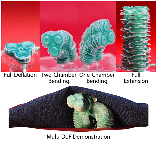
Researchers have developed a soft actuator with minimal footprint and maximized functionality.
The Stacked Balloon Actuator, or SBA, can expand up to several centimeters from a nearly flat state and generate newton-level forces in various configurations.
The researchers envision new opportunities in unstructured environments, from surgery to exploration and search-and-rescue.
1. Introduction
Soft robots are exploited for their conformability in areas where conventional robot rigidity would be a detriment [1–5], such as the exploration of complex environments and manipulation of delicate structures [6–10]. By passively deforming upon contact with their surroundings, soft robots provide adaptability and safety in these unstructured environments. For example, robots designed for surgery, exploration, or search-and-rescue often must 1) squeeze through small apertures before dexterously interacting with larger workspaces (Figure 1 a); 2) brace against external structures to generate a temporary fixed constraint in the system (Figure 1 b); and 3) restructure their surroundings to better operate within them [6, 11] (Figure 1 c). However, being able to demonstrate all of these functionalities within a single soft robotic platform remains a challenge in current soft robotic architectures.
Figure 1:
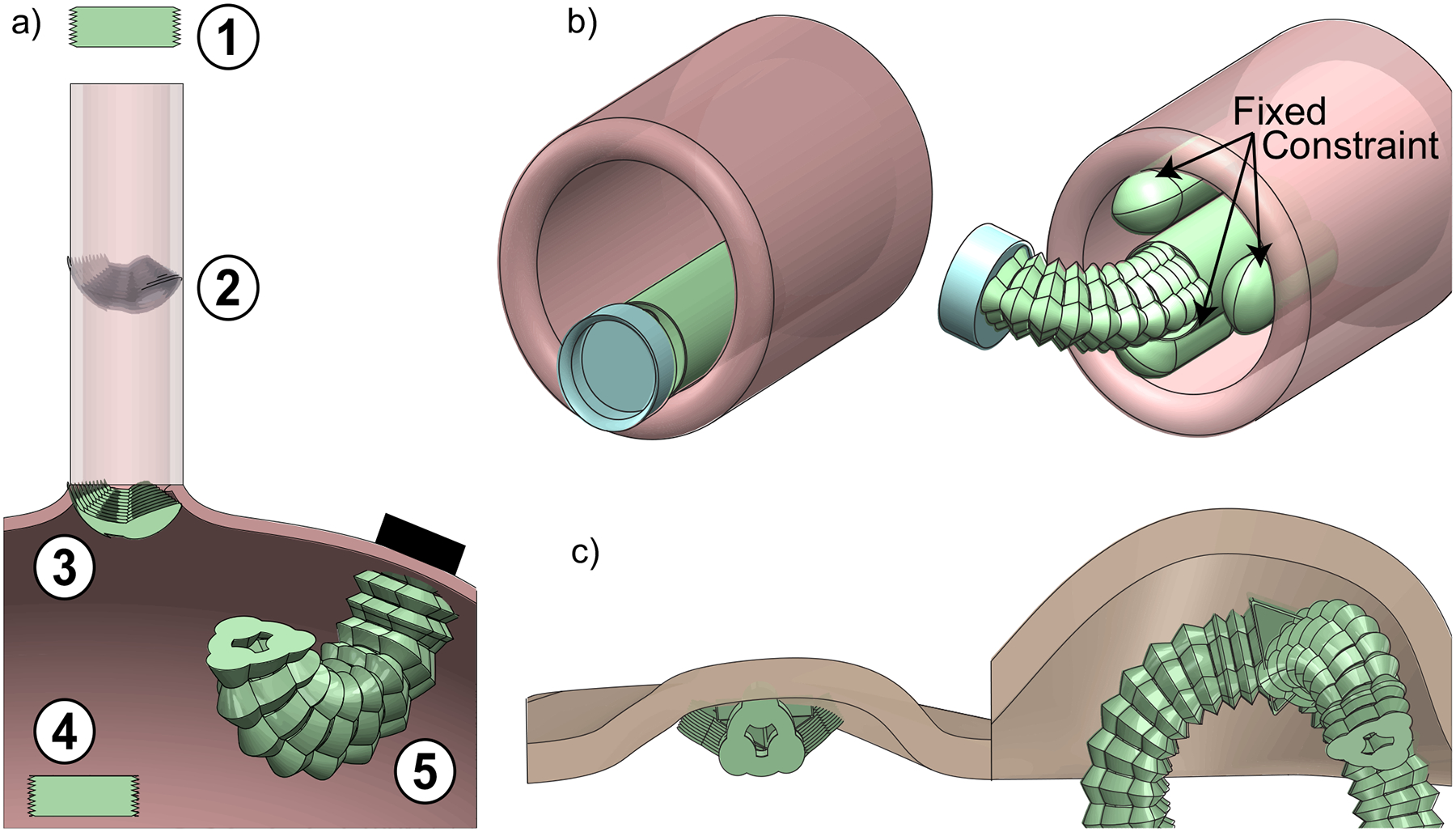
Scenarios enabled by the proposed SBAs. a) A 3-DoF SBA is deployed through a small tube (1–2) before emerging into a cavity (3–4) and magnetically fixing to the wall to manipulate the surroundings (5). b) A 3-DoF SBA is connected to an inflatable expansion mechanism to brace to a tube while grasping with a suction cup. c) A two-legged standing robot made of three 3-DoF SBAs starts flat in a collapsed environment and then expands to create its own workspace.
Among the different actuation strategies for soft robots, fluidic actuation is widespread because it combines ease of fabrication, high power densities, large forces, and large strokes [12–14]. Soft fluidic actuators can be divided into two architectures: elastomeric and inflatable [15, 16]. Elastomeric fluidic actuators rely on the deformation of their constitutive elastomer in response to the pressurization of a chamber [17, 18]. However, part of the energy input from pressurization is lost when straining the elastomer, reducing their efficiency in translating input energy into useful work [15, 19]. Additionally, the incompressibility of elastomers and the need for pneumatic chambers with a non-zero resting volume limit their non-actuated size, thus requiring specialized equipment and manufacturing to develop increasingly small structures [20,21].
Inflatable systems provide an alternative to elastomeric systems [6, 22, 23]. Inflatable growing robots, for example, have demonstrated controlled maneuvers through small apertures and around various obstacles [6, 22, 23]. A widely adopted method for growth-based actuation is eversion, in which a thin layer of polymer film is deposited at the robot’s tip through a central channel [23]. However, this mechanism can impose limitations on dexterity [23, 24]. They also require additional actuation strategies to steer, such as cables, which may lead to frictional losses in the system [22]. Alternative inflatable systems include pouch motors [25–27], pneumatic artificial muscles [28–30], and soft multi-layer structures which exploit additive 2D manufacturing of thin polymer films [31–33]. This 2D layered manufacturing process provides the advantage of large pre-programmed motions from a nearly flat deflated state [31], and previous works have demonstrated 1-DoF bellows actuators using this process [14, 34–37]. Such actuators are composed of four to six balloon-like units stacked on top of each other [14, 36, 37], so we therefore refer to them as Stacked Balloon Actuators (SBAs). A benefit of SBAs is that different kinematics can be programmed by changing the design of the constituent polymer film layers, unlike elastomeric actuators which require entire mold replacements [14]. Additionally, their non-actuated size is solely determined by the number and thickness of their constituent layers, making them well suited to fit into very small spaces without compromising their capability to generate large strokes [14].
Here, we present a two-fold contribution to the state of the art. First, we present a high throughput manufacturing method for single- and multi-DoF SBAs, modeling strategies to capture their kinematics, and experimental characterizations. Second, we apply SBAs in complex architectures, enabling new designs and functionalities for soft robots. In relation to the first contribution, we build upon prior works in SBA design and manufacturing [14,36,37] to present a method for improved SBA yield and scalability without increasing fabrication time. The proposed process enables the fabrication of SBAs with a large number of layers, thus increasing their stroke, as well as the monolithic integration of multiple DoFs in the same actuator. We also introduce a geometric model to calculate the kinematic relationship between height and input volume, and we present a finite element model (FEM) which simulates a 3-DoF SBA in real time. We then perform experimental characterizations of the proposed SBAs to validate the theoretical predictions and characterize actuator performance. In relation to the second contribution, we demonstrate three scenarios in which we combine the proposed SBAs, showing their ability to squeeze through small apertures, brace to their surroundings to increase force output, and generate a workspace from a collapsed environment (Figure 1).
2. Design & Fabrication
Building soft SBAs from a 2-D process relies upon the selective bonding of three functional layers. A structural layer forms the “skin” of the actuator; a glue layer bonds the structural layers in pre-designed areas during the heat-bonding process; and a mask layer prevents the structural layers from bonding in undesired areas. Table 1 summarizes the layer materials used in prior works, including Thermoplastic Elastomer (TPE), Low-Melting (LM) Thermoplastic Polyurethane (TPU), and Polytetrafluoroethylene (PTFE).
Table 1:
Materials used to build soft SBAs
In this work, we manufacture soft SBAs by heat-pressing 38 μm thick layers of TPE (Fibreglast, Stretchlon 200) and 25 μm thick layers of PTFE (Teflon). The Teflon layer is used to prevent TPE bonding in pre-designed locations and thereby embed the inflatable balloon geometry. Starting from processes developed in prior works [14,36], we identified two primary modes of device failure: leakage and over-melting. Leakage is detected by pneumatically inflating an actuator underwater and locating sources of bubbles. Leaks tend to be caused by small “TPE bonding regions” and “spatial pressure fluctuations”. The TPE bonding regions are the pre-designed areas where one TPE layer bonds to another TPE layer (Figure 2 f). If these regions are too narrow, the risk of leakage increases due to the heightened chance that the layers do not fully bond together. We found that a 0.75 mm bonding region is the minimum width to promote proper bonding and thus mitigate leakage.
Figure 2:
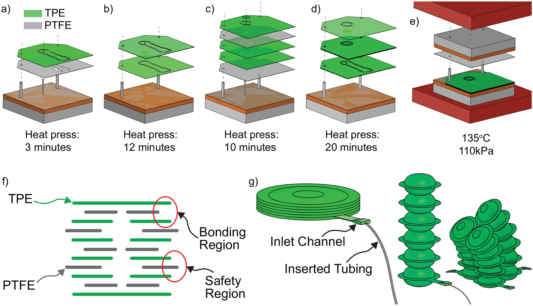
Overview of SBA fabrication process. a) Bottom Balloon: The upper two layers are flash-bonded so they stick together. b) Bottom Balloon: The bottom layer of TPE is laid down with the flash-bonded layers from (a) placed on top, and the full bottom balloon is bonded. c) Middle Balloons: All of the middle layers, minus the final layer of TPE, are flash-bonded. d) Full SBA: All the layers are combined and bonded. e) Heat bonding at 135°C and 110 kPa. f) Layers scheme showing the locations of the 0.75 mm TPE bonding regions and the 0.50 mm Teflon safety regions. g) (Left) Inlet tubing is inserted and sealed into the TPE inlet channel. (Right) CAD rendering of single and 3-DoF SBAs.
Spatial pressure fluctuations occur because the laser-cutting pattern varies between different layers of TPE and Teflon (Figure 2 a–f). Because of the uneven distribution of cuts from layer to layer, the pressure distribution becomes uneven when all the layers are stacked and heat-pressed at once. As a result, some areas do not receive adequate pressure to fully bond. To mitigate this issue, the heat-bonding process was split into four parts to ensure similar layer patterns are heat-pressed together before being combined with dissimilar patterns, as shown in Figure 2 a–d. First the bottom balloon, which contains the fluidic inlet channel, is heat-pressed (Figure 2 a–b). The bottom balloon is bonded separately because the inlet channel layers are dissimilar to the rest of the balloon layers. Once the bottom balloon is fully bonded, then the rest of the balloons are bonded onto it (Figure 2 c–d). This ensures that all areas of the actuator receive an even amount of pressure at some point during the bonding process. The fabrication process consists of the following steps: 1) The upper two layers of the bottom balloon are “flash-bonded” at 135°C and 110 kPa for 3 minutes (Figure 2 a). This step is considered a flash-bond because the layers just barely stick together. These layers are aligned with a dowel pin placed in the chamber’s central channel, enabling precise positioning about the chamber’s central axis. 2) The bottom-most layer is added to the laminate and heat-pressed at 135°C and 110 kPa for 12 minutes, providing a full bond (Figure 2 b). These layers are aligned without a dowel pin placed in the central channel, since the bottom-most layer does not contain a central channel opening. 3) The rest of the layers are separately bonded in a similar manner: first, the middle balloon layers are flash-bonded with a central alignment pin at 135°C and 110 kPa for 10 minutes (Figure 2 c). 4) The upper-most layer is added and the entire laminate is heat-pressed for a full bond, which takes twenty minutes at 135°C and 110 kPa (Figure 2 d). This step is performed without a central dowel pin, since the bottom-most and top-most layers do not contain central channel openings. 5) Once the SBA laminate is bonded, tubing (Braintree Scientific Inc., RPT040) is inserted into the bottom balloon’s inlet channel (Figure 2 g) and sealed with a small drop of adhesive (Loctite Vinyl, Fabric & Plastic Flexible Adhesive).
The second failure mode is over-melting, wherein molten TPE flows past the Teflon mask layer and bonds to other TPE layers where not intended. The over-melting issue is caused by small “Teflon safety regions” and high bonding temperatures. The Teflon safety regions are areas where the Teflon layer is positively offset past the edges of the adjacent TPE layers (Figure 2 f). We found that a positive offset of 0.5 mm reduces the chance that molten TPE will flow past the Teflon mask layers and cause over-melting. Additionally, heat-bonding the layers at lower temperatures and higher pressures was found to mitigate over-melting. Given Stretchlon TPE’s melting point of 120°C, a bonding temperature of 135°C with a pressure of 110 kPa was found to reduce over-melting with respect to the 150°C and 70 kPa proposed in the state of the art [14,36].
The modular nature of the fabrication process also allows the number of DoFs of an SBA to be increased by modifying individual layer designs. We therefore designed and fabricated a monolithic 3-DoF SBA composed of three chambers constrained in parallel, as shown in Figure 2 g. We chose three DoFs because this is the minimum number required to achieve omnidirectional bending. The three-lobed cross section of this SBA fits inside a 15 mm circumscribed circle and can fold to squeeze through a channel down to 9.25 mm in diameter. The 3-DoF SBA’s chambers are each 5 mm in diameter, and it has a 2 mm diameter central channel to allow for instruments or end-effectors to pass through. The same fabrication steps are used regardless of the number of DoFs, with the only changes occurring in individual layer designs. Thus, both a 1-DoF SBA and a 3-DoF SBA can be fabricated in ≈ 1.75 hours.
2.1. Multi-DoF Systems for Functional Demonstrations
We arranged 1-DoF and 3-DoF SBAs in three different configurations to demonstrate key functions of SBAs. (1) A magnetic base (KJ Magnetics, D11SH) was fixed to a 3-DoF SBA with a small drop of adhesive (Loctite Vinyl, Fabric & Plastic Flexible Adhesive). This design was squeezed through a small aperture to reach a larger cavity, where an external magnet (KJ Magnetics, D64) fixed its base to the cavity wall (Figure 1 a). (2) A radial expansion mechanism was fabricated by fixing three oblong, 1-DoF SBAs around a silicone tube of outer diameter 15 mm. Each 1-DoF SBA had a 11.5 × 20 mm cross section, and all three were evenly spaced apart and bonded onto a single sheet of TPE during fabrication. The planar sheet of TPE was then wrapped around the silicone tube, ensuring that all three SBAs were located 120° apart. In total, the radially placed SBAs added 330 μm to the total diameter of the tube when deflated. Thus, the expansion mechanism could deflate to 15.33 mm in diameter, and inflate to a diameter of ≈ 28 mm. A 3-DoF SBA was then fixed to one end of the expansion mechanism using adhesive (3M, 1587), and a silicone (Ecoflex 030) suction cup was placed at the SBA’s tip. The suction cup’s vacuum line fit inside the 3-DoF SBA’s 2 mm diameter central channel. This arrangement used the expansion mechanism to brace against an external lumen and increase stability during a manipulation task (Figure 1 b). (3) Two separate 3-DoF SBAs were fixed about a soft silicone tube using adhesive (3M, 1587). A third 3-DoF SBA was attached to one end of the tube. The two circumferential SBAs could inflate radially, and the third SBA could inflate axially. This design demonstrated the ability of the actuators to collapse during deployment and then restructure the surrounding environment once actuated (Figure 1 c).
The majority of the post-processing steps requiring external adhesion to combine multiple SBAs can be performed in a single fabrication step. Here, we performed those steps in post-processing due to the size limitation of the available equipment. Specifically, we used a heat press (Carver, Inc., 5420) with a heated area of 6″ × 6″.
3. Modeling Approaches
Multiple approaches were investigated to model SBA height at given volumetric inputs. Previous works have analyzed SBAs based on Paulsen’s model of a Mylar balloon: either deflated or fully inflated [37,38]. While this method accurately predicted SBA height at full inflation, it is not capable of capturing intermediate stages of inflation. Other methods must be investigated if we intend to use SBAs not as binary actuators, but as fully-controlled manipulators. We thus present two approaches: geometric modeling and FEM. In all the proposed models, we consider an individual balloon as the fundamental base unit of each SBA, given that a single balloon can be repeatedly stacked and aligned in different ways to program the actuator’s kinematics. The stroke characterizations presented in later sections are therefore normalized to describe a single balloon for ease of comparison with the models.
3.1. Geometric Model
The geometric model assumes TPE inextensibility, and therefore only describes SBA inflation before the TPE begins to strain. We will refer to this phase of inflation as the “geometric regime”, in which the geometry of the balloon changes from flat to expanded, but the TPE itself does not stretch. Upon further inflation, the SBA enters the “strain regime”, in which further expansion of the balloon results from TPE strain. To find a relationship between the volume v inside a single balloon, and the resultant height h of the balloon, we started by looking at the balloon’s vertical cross section (Figure 3). We took pictures of the balloon at incremental stages of inflation, and then used MATLAB to fit a variety of curves to the cross section. We determined that the cross section of the inflated balloon is most accurately described by parabolic curves. Thus, three variables can describe the parabolic curve shown in Figure 3: volume v enclosed by the curve as it is rotated around the y-axis, a coefficient α that dictates the width of the parabola, and the radius ρ of the balloon at different inflation increments. We established the following three equations to solve for these three variables:
| (1) |
| (2) |
| (3) |
where l is the arc length of the curve, equivalent to the radius of the balloon at full deflation. This system of equations was solved using Mathematica (Wolfram Alpha LLC), which gives an equation for v with respect to h. After removing higher order terms the resulting approximation is the following:
| (4) |
Figure 3:
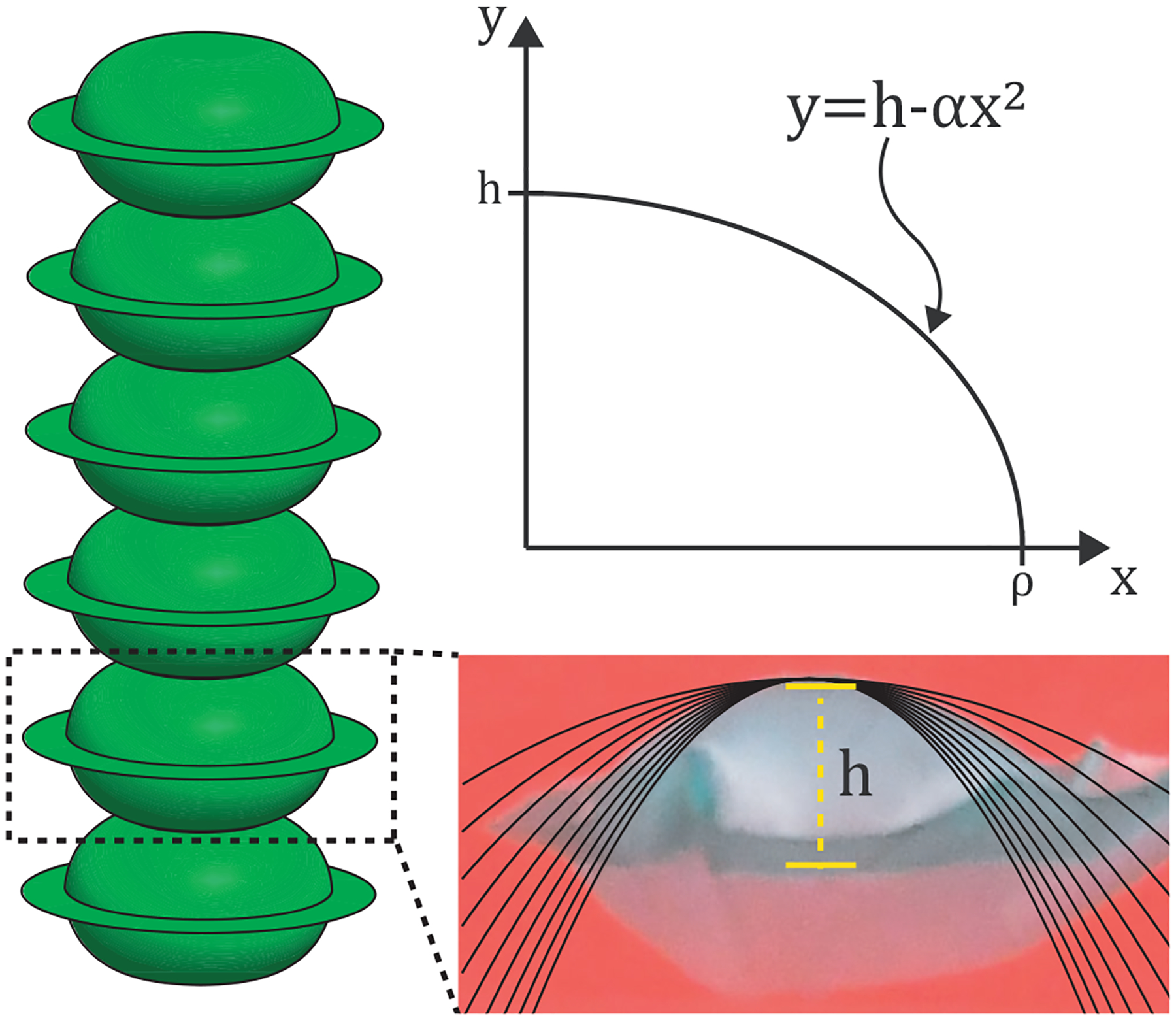
Considerations for geometric modeling of a SBA. (Left) A single balloon is taken as the base unit for the analytical model. (Bottom) A balloon at different stages of inflation was fit with different types of curves, showing that parabolas best describe their geometry. (Top) The first quadrant of a single-balloon cross section can be described by Equation 2.
The Mathematica notebook containing the full derivation is presented in the Supplementary Materials. This geometric model relates the volume and height of a single balloon, thereby constituting a kinematic relationship. Since each chamber of a SBA is essentially a stack of balloons, we assume the volume and height of a n-balloon SBA can simply be multiplied by n. This geometric model is valid only for the geometric regime and does not account for external forces.
3.2. Finite Element Modeling
FEM allows for the integration of the laws of continuum mechanics. However, the discretization necessary to converge the constitutive partial differential equations requires many elements or elements of higher order, often making them computationally expensive. Here we compared FEM in both ABAQUS (Dassault Systèmes) and Simulation Open Framework Architecture (SOFA). The ABAQUS model presents a FEM of a single balloon expanding in response to an input pressure. The SOFA model uses model order reduction techniques to obtain much faster results by mapping the system mechanics into a reduced order space [39]. As such, the SOFA model is able to capture the motion of a full 3-DoF SBA in real-time. Furthermore, the ability of SOFA and the SoftRobots plugin to handle external contact forces in an inverse model in real-time makes it a desirable candidate for the control of soft robots interacting with the environment [40,41].
3.2.1. FEM through ABAQUS
We modeled a single balloon in ABAQUS by imposing a range of internal pressures from 0 to 6 kPa (Figure 4 a). Here we were interested in the internal pressure required to inflate the actuator for comparison with experimental data. The single balloon model consists of two layers of TPE 38 μm thick. An inner pocket of thickness 25 μm and with a diameter of 5 mm was added between the centers of the TPE layers to simulate the Teflon mask, and a circumferential ring of width 0.75 mm was added around the edges to simulate the bonding region. The density of Stretchlon TPE was experimentally determined to be 1122 kg/m3. The Poisson’s ratio was set to 0.2, and the Young’s Modulus was taken as 10 MPa from [14]. A pressure load was applied to the inner surfaces of the actuator, and the jobs were run through a virtual software platform (Citrix Workspace). We discuss the results of the FEM compared to experimental data in Section 4.2.
Figure 4:
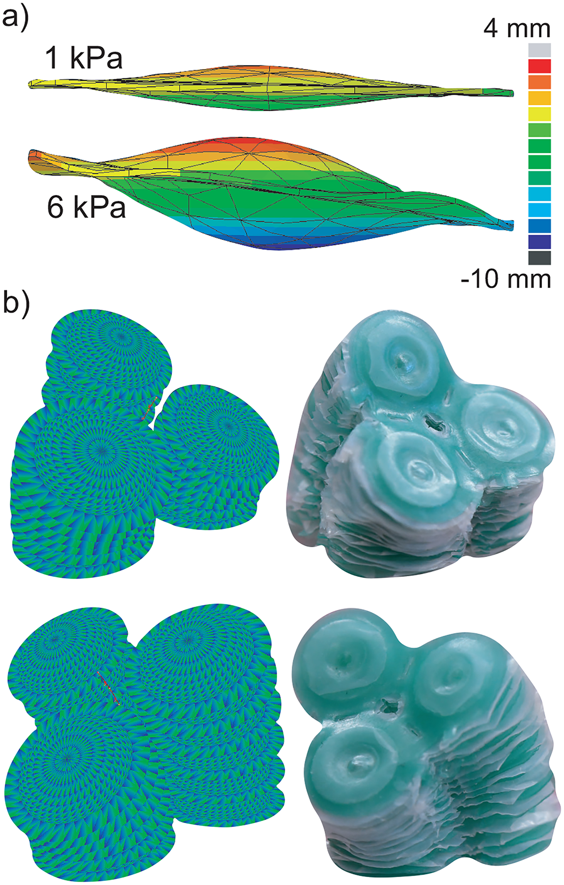
FEM simulations results. a) The balloon deformations from the FEM simulation in ABAQUS are shown at 1 kPa and 6 kPa. b) The results of the real-time FEM simulation in SOFA for a 3-DoF SBA are juxtaposed with a 3-DoF SBA in two different configurations.
3.2.2. Real-time FEM through SOFA
We simulated a full 3-DoF SBA in SOFA for comparison with experimental values and demonstration purposes (Figure 4 b). This model required a mapping between two spaces: an FEM space and a reduced order reference space. In the FEM space, we defined nodes based on the 3D mesh file of our SBA geometry. We then reduced the space of the mesh nodes by defining an imaginary backbone curve along with nine reference points, each with six DoFs to define possible torsion. We defined a kinematic relationship between the reference points in the reduced order space and nodes in the FEM space as x = 𝓐(q) where x is the position vector of the FEM nodes and q is the position vector of the nine backbone reference points. 𝓐 is a non-linear function that maps the set of reduced order reference points to the set of FEM mesh nodes. Once in the FEM space, the internal forces f(x) at each mesh node could be calculated in response to external forces such as inflation pressure. To transfer these internal forces back to the reduced order space, we multiplied by the transposed Jacobian of 𝓐.
| (5) |
This system can be thought of as a kinematic relationship because it relates inputs from the FEM space to backbone position in the reduced space. Thanks to this direct approach, we can obtain a compromise between computation speed and model accuracy. Specifically, we see that SOFA can run the resulting simulation at ≈ 10 Hz (i.e. 10 updates per second). The comparison between the model’s prediction and experimental values is discussed in Section 4.2. Footage of the real-time simulation is shown in the Supplementary Videos.
4. Results and Discussion
The proposed manufacturing processes are critical to yield repeatable and consistent SBAs. They allowed us to build 1-DoF and 3-DoF SBAs in ≈ 1.75 hours, with under 10% of fabrication attempts experiencing either of the two failure modes previously discussed. The process also guarantees geometric consistency between balloons, with no more than 100 μm error from the laser cutting process, and 4 μm error from the alignment dowel pins. We found the burst pressure of these SBAs to be 367 ± 18 kPa, ≈ 3.5 times larger than the 104.8 ± 3.2 kPa reported in [14]. This significantly increased burst pressure demon strates the robustness of the proposed fabrication process. We were also able to build successful 1-DoF and 3-DoF SBAs with up to 20 balloons stacked together, while SBAs in prior works did not exceed 6 balloons [14, 36, 37]. Prototypes are shown in Figure 5 in non-actuated and pressurized states. The following section provides SBA characterizations including energy, stroke, force, and workspace, as well as comparisons with the previously discussed models. Experimental setup can be found in Section 7.
Figure 5:
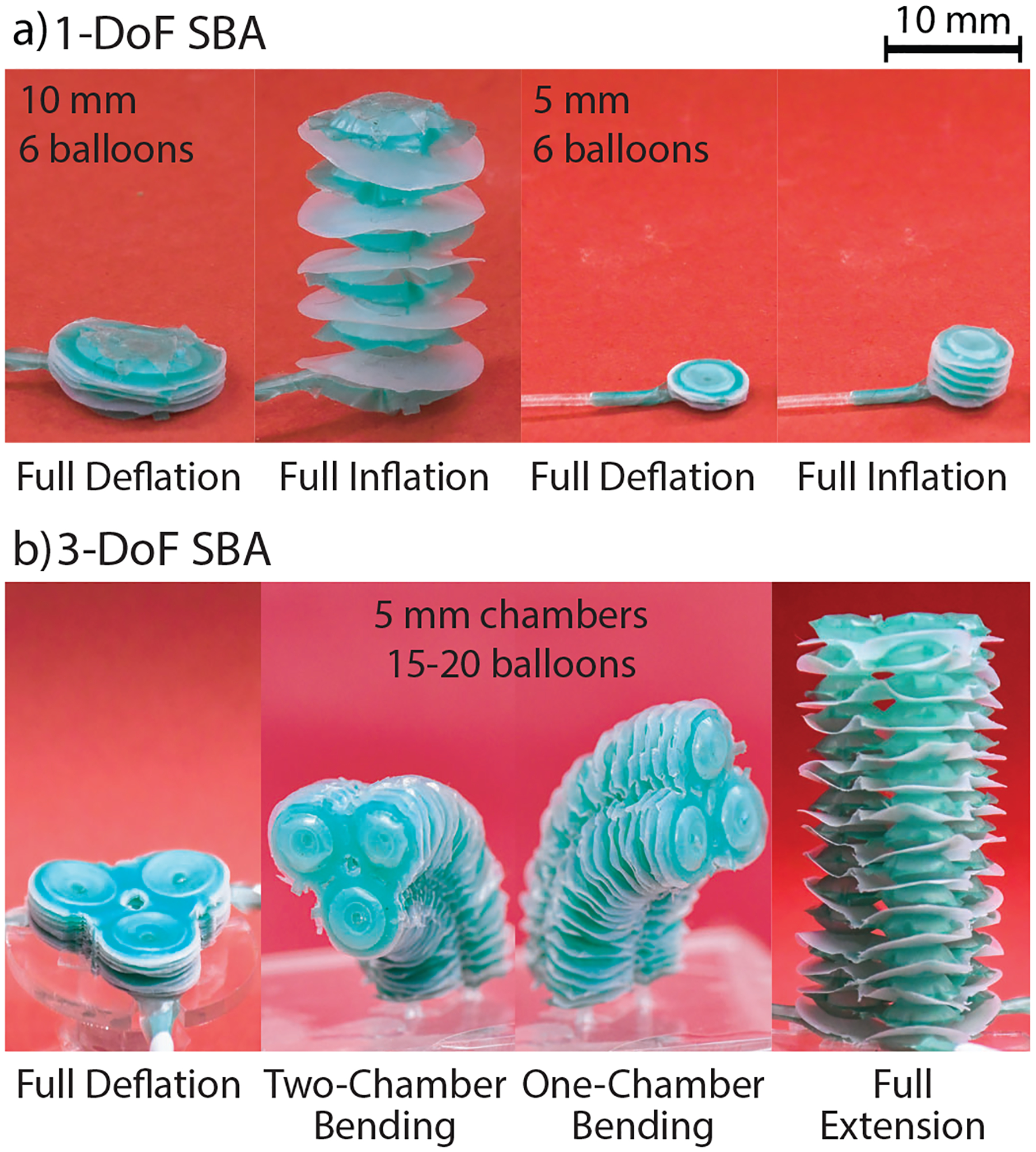
Fabricated prototypes of SBAs. a) 1-DoF SBAs with diameters d = 10 mm and d = 5 mm are shown in their deflated and inflated states. b) a 3-DoF SBA with individual chamber diameters d = 5 mm is shown in its deflated state, as well as three actuated configurations: two-chamber bending, one-chamber bending, and extension.
4.1. Energy Characterization
The results of the energy characterization are given in Figure 6. We found the energy in the system by integrating the pressure curves with respect to volume, based upon [12, 19]. The hysteretic behavior demonstrates energy loss through elastic energy dissipation from material strain. The energy entered into the system at a 10 kPa inflation pressure was 45.3 mJ, with a loss of 4.2 mJ. This is comparable to the fast PneuNet actuator, which demonstrated an energy input of 38.1 mJ and a 4.1 mJ loss [19]. However, 10 kPa is also beyond the maximum pressure required for geometric inflation, as discussed in Section 4.2. When the SBA was pressurized to 1 kPa in its geometric regime, it demonstrated an energy input of 531 μJ with a loss of 55 μJ.
Figure 6:
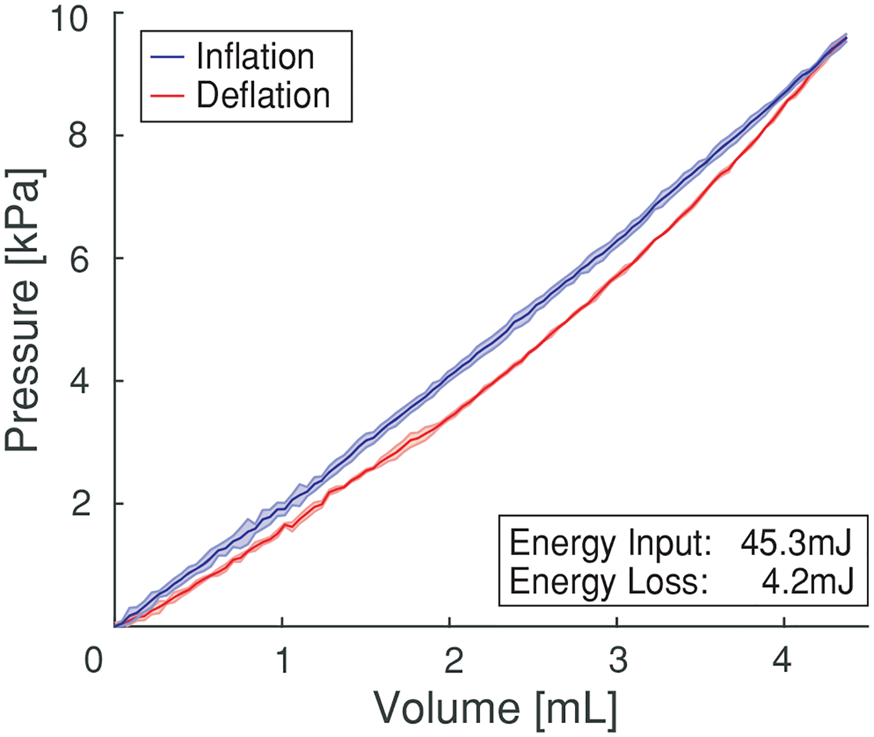
Pressure vs volume hysteresis curve. Experimental curve shows average values with one standard deviation. Pressure vs Volume: one SBA with diameter d = 10 mm was inflated and deflated three times to 1 kPa and 10 kPa. The 10 kPa hysteresis curve is shown, with a loss of 4.2 mJ.
4.2. Stroke Characterization
The stroke characterization results are shown in Figure 7. For ease of comparison and generalization, the results are normalized to one balloon, but they can be multiplied by n to yield the stroke of a SBA with n balloons. Figure 7 a shows a normalized stroke vs volume plot for a 1-DoF SBA with chamber diameter d = 10 mm and both air and water as the working fluid. The plot shows that the geometric model begins to over-predict the experimental curves in both cases. The model can capture the extension of the actuator up to a normalized volume of 0.045 ml with a maximum error of 130 μm when inflated with air. When using an incompressible fluid like water, the model captures the behavior of the actuator up to a normalized volume of 0.086 ml with a maximum error of 120 μm before straying from the model. The over-prediction occurs because the model assumes TPE inextensibility, and thus does not account for the strain regime. When the SBA begins to strain rather than expanding geometrically, vertical expansion becomes less efficient because work must also be exerted toward expanding the elastomer itself, and so actual expansion becomes slower than predicted expansion. Notably, the model follows the experimental curve from the water trial longer than the air trial because of air’s compressibility. Figure 7 b shows normalized stroke vs volume for a 1-DoF SBA with chamber diameter d = 5 mm and water as the working fluid. The initial SOFA model consistently underpredicts the experimental curve with ≈ 13.3% error. This behavior can be attributed to the fact that the SOFA model was generated using SBA chambers starting at ≈ 19 μl per balloon. This was done to avoid instabilities from excessive mesh deformation, but it also means the model cannot accurately capture the initial inflation behavior. Furthermore, the SOFA model uses a coarse mesh to allow for a high computation speed of 10 Hz. This high simulation speed necessarily decreases the simulation’s accuracy. Despite this, after translating the model curve by a 75 μm correction to account for the initial offset introduced in the model, the model can capture the actuator deformation with a maximum error of 4.9%. This also means that in a 15 balloon SBA that inflates almost 2 cm in its geometric regime, only the first 3 mm of inflation would not be accurately modeled.
Figure 7:

Stroke characterizations and comparison to kinematic models. Experimental curves show average values with one standard deviation. a) Stroke vs Volume: one 1-DoF SBA with diameter d = 10 mm was inflated three times with air, and a separate 1-DoF SBA was inflated three times with water. The experimental stroke curves are reported against the geometric model. b) Stroke vs Volume: one 1-DoF SBA with diameter d = 5 mm was inflated three times with water. The experimental stroke curve is reported against the SOFA model. c) Stroke vs Pressure: one 1-DoF SBA with diameter 5 mm was inflated three times with air to be compared against data from the ABAQUS simulation.
Figure 7 c shows normalized stroke vs pressure for a 1-DoF SBA with chamber diameter d = 5 mm and air as the working fluid. After ≈ 0.95 kPa, the ABAQUS model begins to overpredict the experimental curve, and the slope of the experimental curve continues to decrease, indicating increased strain to the elastomer. Thus, SBAs only require pressure input on the order of kilopascals to experience full geometric expansion.
4.3. Force Characterization
Figure 8 shows the results from the force vs pressure tests. For all trials, the actuators were tested quasi-statically up to internal pressures of 100 kPa, in accordance with standard protocols developed in [12, 14, 19, 42–44]. These tests show the capability to generate force in both extended and bent configurations. As shown in Figure 8 a, the 3-DoF SBA generates a max force of 4.87 ± 0.02 N when flat, 4.07 ± 0.07 N at 25% max inflation, and 2.40 ± 0.03 N at 75% max inflation. The 1-DoF SBA attains a max force of 1.48 ± 0.04 N when flat, 1.01 ± 0.01 N at 25% max inflation, and 0.64 ± 0.01 N at 75% max inflation. Accordingly, the 3-DoF SBA exerts between three and four times more force than the 1-DoF SBA for a given height increment. The 3-DoF actuator also benefits from inherent radial support that arises from its tri-lobed geometry, thus reducing the likelihood of buckling during expansion and further aiding its force output. As shown in Figure 8 b, the 3-DoF SBA exerts 3.22 ± 0.12N max at 30° bending, 1.41 ± 0.05N max at 60° bending, and 0.55 ± 0.02N max at 90° bending. While there is a drop-off in force output for higher degrees of bending, the 3-DoF SBA still generates newton-level forces in all configurations.
Figure 8:
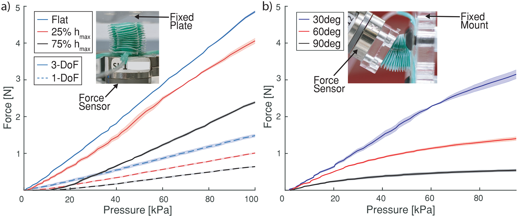
Force characterizations for SBAs in extension and bending. Experimental curves show average values with one standard deviation. a) Force vs Pressure: one 1-DoF SBA (solid line) and one 3-DoF SBA (dashed line) were inflated against a force sensor at three height increments. The inset shows a picture of the tests setup with a 3-DoF SBA at 25% elongation pushing against the force sensor. b) Force vs Pressure: one 3-DoF SBA was inflated against a force sensor at three bending angles. The inset shows a picture of the tests setup with a 3-DoF SBA pushing against a force sensor at 30°.
Notably, the robot generates more force when constrained in a less extended state, and more force when allowed to inflate to a more extended state. The principle of virtual work can explain this phenomenon: the work done to generate an external force can be equated with the work done by internal pressure to inflate the actuator. In a quasi-static state, the amount of work done due to inflation remains constant, so as the actuator height increases it must generate less force to preserve equality.
We neglected the effect of gravity on the SBA force output. To validate this assumption, we calculated the theoretical maximum weight of the actuator with both air and water as a working fluid. The calculation steps are shown in the Supplementary Materials. As a result, we found that accounting for gravity would add an error of 0.004 N with air as the working fluid and 0.022 N with water as the working fluid. Between all of the force tests, the measurement errors ranged from ±0.01 N to ±0.12 N. Since the force contribution from gravity is on the lower end of this error range, we deemed it sufficiently small to neglect.
4.4. Bending Stiffness
Bending stiffness was determined by approximating the pressurized actuators as passive and homogeneous beams in a cantilevered position and applying a known force at their tip, as done in [14, 25, 31, 45–49]. Using force and displacement data, an approximate Young’s modulus was computed for 1-DoF and 3-DoF SBAs. F is the maximum force applied at the tip of the beam, l is the beam length, δ is the beam tip deflection under load, and I is the second moment of area for the cross section in bending. To find the second moment of area, the 1-DoF and 3-DoF SBAs were modeled in Solidworks (Dassault Systèmes), and the “Section Properties” feature was used to determine the second moment of area for the cross section of interest. The resulting modulus values represent approximations based on the assumption that the SBAs are homogeneous beams. These values allow us to quantify the stiffness variation between 1-DoF and 3-DoF actuators and provide an indication of the response of the actuator to external forces. We also show the ability to simulate the effect of external forces using ABAQUS in the Supplementary Materials.
The Young’s modulus approximation for a 1-DoF SBA is E = 35 kPa, and the modulus for a 3-DoF SBA is E = 60 kPa. Such low values can be explained by the geometry of the actuators. When inflated, the connection between each balloon can be viewed as a 2-DoF spring joint, about which the next balloon can rotate. The more balloons are added to the stack, the more spring joints there are in series. This necessarily decreases the actuator’s effective spring constant, making the radial bending stiffness of SBAs much lower than their axial strength. Their low bending stiffness also makes SBAs an excellent candidate for operation in delicate environments, since they can easily deform upon radial contact with external objects.
4.5. Actuation Speed and Power Density
It was shown in Section 4.2 that the inflation of soft SBAs is largely driven by a change in geometry rather than strain to the elastomer, allowing them to be actuated more quickly and efficiently than many silicone actuators. For a pneumatically inflated SBA, an actuation speed of 67 ± 11 ms was demonstrated. With water, an actuation speed of 920 ± 80 ms was demonstrated. In both cases, full actuation was considered to be 10 kPa. Comparatively, the fast Pneunet actuators from [19] achieved full pneumatic actuation in 130 ms.
Based on the pneumatic speed and the maximum generated forces, maximum power densities can be calculated. This method is detailed in Section 7 to calculate power densities for elastomeric and inflatable soft actuators. The results are reported in Table 2.
Table 2:
Power Densities at Various Height Increments
| 1-DoF | 3-DoF | |
|---|---|---|
| 75% Max Height | 2.73 | 2.87 |
| 25% Max Height | 4.31 | 4.86 |
| 0% Max Height | 6.31 | 5.81 |
Soft elastomeric actuators have power densities ranging between and [31]. Soft inflatable actuators with high power density have been demonstrated in Li et al. with a peak power density of ≈ [50].
4.6. Workspace Characterization
Figure 9 shows the results of the workspace characterizations. In Figure 9 a we show an actuation time of ≈ 0.56s to reach 30.3 ± 1.3° steady state, ≈ 0.78s to reach 58.5 ± 1.2° steady state, and ≈ 0.91s to reach 89 7±2.0° steady state. The max steady state deviation of 2.0° for any angle, across separate trials and actuators, demonstrates consistency in reaching a desired bending angle for given pressure inputs. SBA workspace results are shown in Figure 9 b. Since the actuator is axisymmetric, a ≈ 120° section of a 3-DoF actuator’s reachable workspace is representative of the whole workspace. The SBA starts at a deflated height of 0.95 mm and reaches 17.5 mm, or 1.2 mm per individual balloon. The actuator achieves a maximum bending angle of 81 ± 6°. Additionally, the height and bending angles can be increased by adding more balloons to the SBA, while only making a micron-scale change in deflated thickness.
Figure 9:
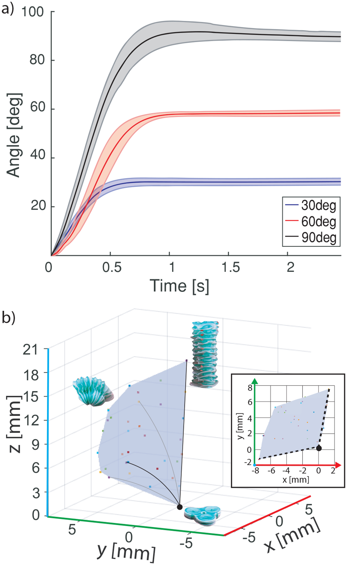
Bending and workspace characterizations. Experimental curves show average values with one standard deviation. a) Actuator bending: two 3-DoF SBAs were inflated and their tip positions were measured for three bending angles. b) Workspace: 120° section of a 3-DoF SBA’s total workspace. The inset shows a 2D top view, zoomed in to fit the section to the axes.
5. Functional Demonstrations
Three functional demonstrations were performed based on the examples from Figure 1. These demonstrations highlight the SBA’s ability to: 1) squeeze through small apertures to reach a cavity and then interact with its surroundings; 2) brace against its surroundings to create a local fixed constraint, thereby improving stability and force transmission throughout the structure; and 3) structure its surroundings to create its own workspace. To demonstrate such functionalities, three architectures were built (Section 2.1). Results from the demonstrations are shown in Figure 10, 11, 12, and in the Supplementary Videos. In the first demonstration, a single 3-DoF SBA with a magnet attached to its base was pushed through a small lumen with a diameter of 9.25 mm. Once the SBA reached the aperture of the lumen, its base was fixed to the wall of the cavity with an external magnet (Figure 10). The SBA could then inflate and push a golf ball weighing 46 g. As demonstrated in the Supplementary Video, the SBA was able to interact with the golf ball regardless of the ball’s position within the cavity due to the SBA’s high expansion ratio. By inflating from a flat, folded configuration to ≈ 2 cm in height, the SBA could interact with a much larger environment than the small lumen from which it emerged.
Figure 10:
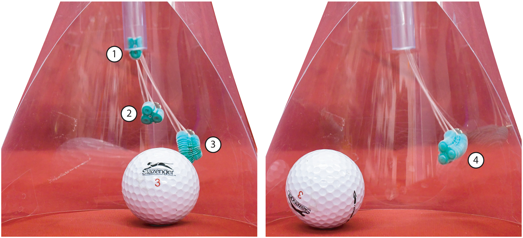
Demonstration of squeezing through a small aperture and operating in a large workspace. The 3-DoF SBA begins folded inside a lumen of diameter d = 9.25 mm (1). It then exits the lumen and is fixed to a wall via an external magnet (2). From its fixed position, it expands to move a golf ball (3–4).
Figure 11:
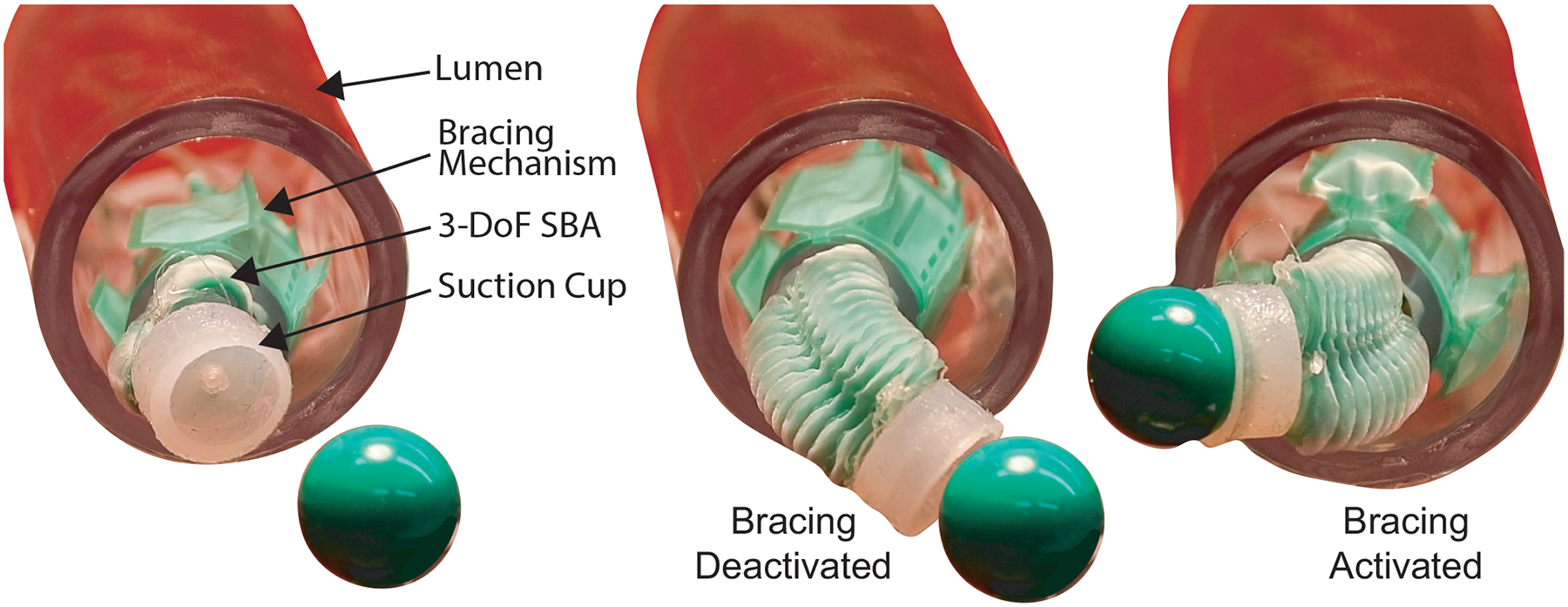
Demonstration of bracing to increase stability during object manipulation. Left: A 3-DoF SBA with a suction cup at the tip is connected to a fully soft radial expansion mechanism. Middle: The expansion mechanism is deactivated, so there is no local fixed constraint, and thus the 3-DoF SBA lacks the mechanical leverage to reach and lift the marble. Right: The expansion mechanism braces against a lumen, allowing a suction cup placed at the tip of the SBA to pick up and place the marble.
Figure 12:
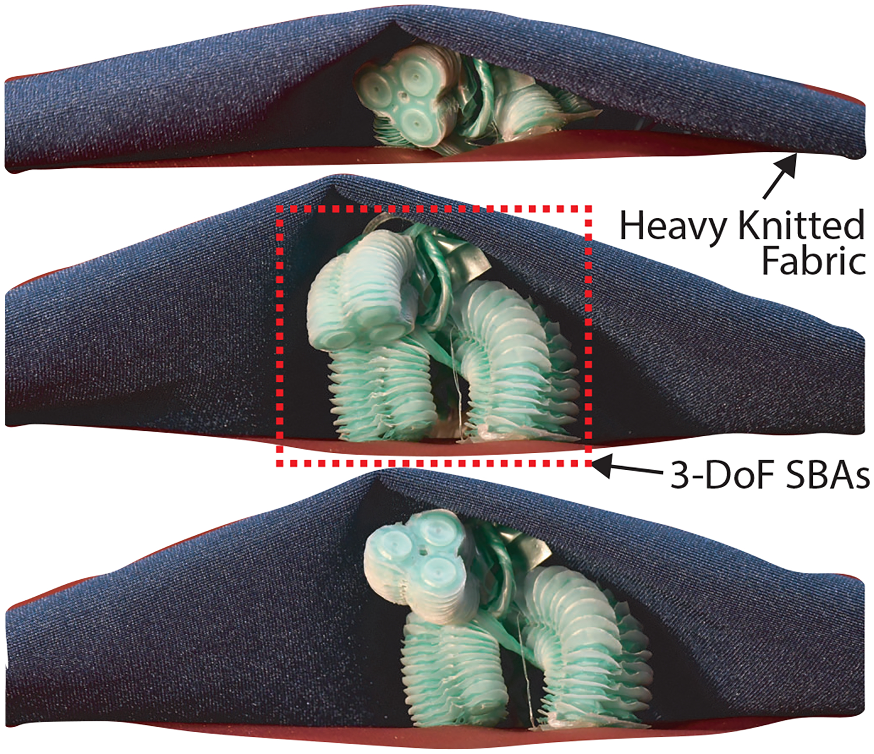
Demonstration of operation in a collapsed environment and workspace generation. Three 3-DoF SBAs are oriented around a central tube such that two act as legs and one acts as a head. The robot demonstrates its ability to expand out of a nearly flat configuration, thus creating its own explorable workspace.
In the second demonstration, a 3-DoF SBA was attached to a radial expansion mechanism. The expansion mechanism could be deflated to a diameter of ≈ 15 mm during deployment. However, when the radial SBAs were inflated, the expansion mechanism increased to 28 mm in diameter. The almost doubled diameter allowed the expansion mechanism to brace against a lumen of diameter 25.4 mm. Using this bracing as a mechanically fixed point, the 3-DoF SBA could lift a 1.2 g marble using a suction cup at its distal tip (Figure 11). However, when the expansion mechanism was deactivated, the reaction forces that previously allowed the tip of the SBA to bear weight disappeared from the system. Thus, the actuator was unable to apply enough force to suction the marble, and instead pushed itself further into the lumen from which it came. The pick and place task is further demonstrated in Supplementary Videos.
Finally, three 3-DoF SBAs were arranged around a soft silicone tube, with two of the actuators acting as legs and the other as a head. As shown in Figure 12, the robot began in a nearly flat state, before “standing up” on two individually controlled legs and raising the heavy knitted fabric on top of it. Once fully standing, the third actuator was able to move and explore the environment independent of the leg actuators.
6. Conclusions
The monolithic fabrication process presented in this paper allowed us to fabricate SBAs with a success rate of 90%. We fabricated both 1-DoF SBAs with diameters of 5 mm and 10 mm, and 3-DoF SBAs with individual chamber diameters of 5 mm and an overall diameter of 15 mm. These actuators start at ≈ 1 mm in height when fully deflated and can expand several centimeters based on the number of stacked balloons. For the purposes of this work, we manufactured SBAs with up to twenty stacked balloons, but the modular fabrication process allows for a large number of balloons to be stacked, limited only by the ability of heat to propagate through the laminate during the bonding process. By increasing the number of balloons in an SBA, we can increase its stroke and geometric inflation range.
A geometric model capable of describing actuator kinematics has been developed and validated, showing the possibility to closely capture the geometric deformations of soft SBAs. FEM-based strategies have also been presented, demonstrating accurate representation of the actuator’s expansion. Additionally, we demonstrated the feasibility of SOFA to model the behavior of a 3-DoF SBA through the real-time FEM shown in the Supplementary Videos.
We also provided extensive characterizations to allow the proposed SBAs to be used as fully controllable manipulators in small, unstructured environments.
Finally, we showed how SBAs can be combined to develop complex, multi-DoF soft structures capable of squeezing in small apertures without compromising their reachable workspace, bracing to their surroundings to improve their force output, and structuring their surroundings to create a workspace from a collapsed environment.
We envision the proposed SBAs enabling new opportunities in unstructured environments, given their ability to expand multiple orders of magnitude while maintaining a minimal footprint when inactive. These features can be particularly valuable in applications such as minimally invasive surgery, where soft robots can provide safer alternatives to current instrumentation, but must often sacrifice dexterity for scalability [13]. Smaller soft robots also tend to generate lower forces, despite many surgeries requiring forces in the newton-range [51]. Another potential application is exploration or search-and-rescue, where one might need to gain access to a collapsed space [6, 20, 24]. SBAs could provide the ability to squeeze into tight spaces and enlarge their environments.
7. Experimental Section
The experimental setups for each test are described below. Additionally, a reference schematic is included in the Supplementary Material.
Burst Pressure:
The burst pressure of three SBAs was determined by inflating them with air using a syringe pump (Harvard Apparatus, Pump 11 Pico Plus Elite). A pressure sensor (Nidec Copal Electronics Inc., P-7100–103G-M5) continuously measured the internal pressure of the actuator chambers until failure.
Energy Characterization:
Pressure vs volume curves were collected with one end of a 6-balloon, 1-DoF SBA of diameter 10 mm fixed to a base and the other end free to expand. The syringe pump infused and withdrew a known volume of water, and the pressure sensor tracked the corresponding internal pressures. This test was performed n = 3 times on one actuator. To calculate energy, the pressure vs volume curves were integrated with respect to volume, which yielded work. The difference in work output between the two hysteresis curves yielded the overall energy loss in the system.
Stroke Characterization:
The strokes of 6-balloon, 1-DoF SBAs with diameters 5 mm and 10 mm were measured by fixing one end to a base and allowing the other end to expand freely. The syringe pump infused fluid into the chamber at a constant rate, the pressure sensor tracked the corresponding internal pressure, and an electromagnetic (EM) position tracking system (Northern Digital Inc., Aurora) collected stroke data. A stroke vs volume test was performed with both air and water to compare the resulting actuator behavior within the geometric regime, while a stroke vs pressure test was performed only with air. One 10 mm SBA was tested n = 3 times with air, and a separate actuator was tested n = 3 times with water. One 5 mm SBA was tested n = 3 times with air.
Force Characterization:
Force vs pressure curves were collected for a 1-DoF and a 3-DoF SBA, each with individual chambers of diameter 5 mm. The SBAs were constrained at {0.0, 25.0, 75.0}% of maximum height. The syringe pump infused air into the SBA at , the pressure sensor tracked the corresponding pressure, and a fixed-position force sensor (ATI Industrial Automation Inc., NANO17) measured the force output. Each actuator was tested n = 3 times at each height increment. Additional force vs pressure curves were taken for a 3-DoF SBA in bending. The SBA was allowed to expand into the force sensor constrained at {30, 60, 90}° relative to the base of the SBA, at which point the trials were run in identical manner to the axial version.
Bending Stiffness:
Bending stiffness tests were performed by fixing one end of a SBA to a vertical platform and inflating it with air. The SBA was held in the inflated position, allowing it to be remain passive and stationary, and thus approximate a cantilever beam. The force sensor mounted to an Instron 5943 machine collected force and displacement data while pressing on the free end of the actuator. The test was run for 1-DoF and 3-DoF SBAs, each tested three times.
Actuation Speed and Power Density:
The actuation speed of the SBAs was characterized for both air and water as a working fluid. For each working fluid, three separate SBAs were tested: two 3-DoF SBAs and a 1-DoF SBA. For the pneumatic speed tests, actuation was achieved with a custom pneumatic control board constructed with an Arduino Mega, fluidic pressure sensors (Honeywell, ASDXAVX030PGAA5), pneumatic solenoid valves (Adafruit, 4663), and an air pump (Adafruit, 4699). The SBA was then inflated at the pump’s maximum flow rate of until the pressure sensors reached 10 kPa. For the hydraulic speed tests, actuation was achieved with the syringe pump (infuse rate of ). A LabView (National Instruments) code was used to stop the syringe pump once the SBA’s internal pressure reached 10 kPa. Video was collected for each trial and analyzed in a commercial video editing software (Adobe Premiere Pro) to determine the time from the actuator’s deflated position to its inflated position.
To calculate power density, we used the equation , where F is force generated by the actuator, v is the speed of the actuator, and m is the mass of the actuator. This method was based on power density characterizations for soft actuators performed in [31, 50].
Workspace Characterization:
SBA tip position was analyzed with respect to time for two separate 3-DoF SBAs, each actuated to {30, 60, 90}° in bending using syringe pumps (infuse rate at ). Tip position was tracked with the EM tracking system. Additionally, the workspace of one 15-balloon 3-DoF SBA was determined by placing an EM tracking probe at its tip. The SBA then swept through a range of inflation values spanning 120° of its overall workspace using the custom pneumatic control board.
Supplementary Material
Acknowledgements
The authors would like to thank Dr. Hugo Talbot for his support in using SOFA.
This work was supported by the National Institute of Biomedical Imaging and Bioengineering of the National Institutes of Health under Award R21EB028363 and by the Office of Naval Research (ONR) grant number N00014-22-1-2244. The content is solely the responsibility of the authors, and does not necessarily represent the official views of the National Institutes of Health. Any opinions, findings, and conclusions or recommendations expressed in this material are those of the author(s) and do not necessarily reflect the views of the ONR.
The Interactive Supporting Information of this article can be found at: https://www.authorea.com/doi/full/10.22541/au.165366614.44273980.
Footnotes
Supporting Information
Supporting Information is available from the Wiley Online Library or from the author.
Contributor Information
Jacob Rogatinsky, Department of Mechanical Engineering, Boston University, Boston, MA 02215, USA.
Kiran Gomatam, Department of Mechanical Engineering, Boston University, Boston, MA 02215, USA.
Zi Heng Lim, Department of Mechanical Engineering, Boston University, Boston, MA 02215, USA.
Megan Lee, Department of Mechanical Engineering, Boston University, Boston, MA 02215, USA.
Lorenzo Kinnicutt, Department of Mechanical Engineering, Boston University, Boston, MA 02215, USA.
Christian Duriez, INRIA, CNRS, Centrale Lille, Team DEFROST University Lille, Lille F-59000, France.
Perry Thomson, Department of Mechanical Engineering, Boston University, Boston, MA 02215, USA.
Kevin McDonald, Department of Mechanical Engineering, Boston University, Boston, MA 02215, USA.
Tommaso Ranzani, Department of Mechanical Engineering, Boston University, Boston, MA 02215, USA; Division of Materials Science and Engineering, Department of Biomedical Engineering Boston University, Boston, MA 02215, USA.
References
- [1].Rus D, Tolley MT, Nature 2015, 521, 7553 467. [DOI] [PubMed] [Google Scholar]
- [2].Jumet B, Bell MD, Sanchez V, Preston DJ, Advanced Intelligent Systems 2021, 2100163. [Google Scholar]
- [3].Whitesides GM, Angewandte Chemie International Edition 2018, 57, 16 4258. [Google Scholar]
- [4].Laschi C, Mazzolai B, Cianchetti M, Science Robotics 2016, 1, 1. [DOI] [PubMed] [Google Scholar]
- [5].Dou W, Zhong G, Cao J, Shi Z, Peng B, Jiang L, Advanced Materials Technologies 2021, 6, 9 2100018. [Google Scholar]
- [6].Hawkes EW, Blumenschein LH, Greer JD, Okamura AM, Science Robotics 2017, 2, 8 3028. [DOI] [PubMed] [Google Scholar]
- [7].Runciman M, Darzi A, Mylonas GP, Soft Robotics 2019, 6, 4 423. [DOI] [PMC free article] [PubMed] [Google Scholar]
- [8].Cianchetti M, Laschi C, Menciassi A, Dario P, Nature Reviews Materials 2018 3:6 2018, 3, 6 143. [Google Scholar]
- [9].Shah DS, Powers JP, Tilton LG, Kriegman S, Bongard J, Kramer-Bottiglio R, Nature Machine Intelligence 2021, 3, 1 51. [Google Scholar]
- [10].Drotman D, Jadhav S, Karimi M, Dezonia P, Tolley MT, Proceedings - IEEE International Conference on Robotics and Automation 2017, 5532–5538. [Google Scholar]
- [11].Harada K, Oetomo D, Susilo E, Menciassi A, Daney D, Merlet J-P, Dario P, Robotica 2010, 28, 2 171. [Google Scholar]
- [12].Marchese AD, Katzschmann RK, Rus D, Soft Robotics 2015, 2, 1 7. [DOI] [PMC free article] [PubMed] [Google Scholar]
- [13].Cianchetti M, Ranzani T, Gerboni G, Nanayakkara T, Althoefer K, Dasgupta P, Menciassi A.
- [14].Ranzani T, Russo S, Schwab F, Walsh CJ, Wood RJ, Proceedings - IEEE International Conference on Robotics and Automation 2017, 1125–1131. [Google Scholar]
- [15].Gorissen B, Reynaerts D, Konishi S, Yoshida K, Kim J-W, Volder MD, Advanced Materials 2017, 29, 43 1604977. [DOI] [PubMed] [Google Scholar]
- [16].Baines RL, Kalyan Patiballa S, Kramer-Bottiglio R, 2021 IEEE 4th International Conference on Soft Robotics, RoboSoft 2021 2021, 29–34. [Google Scholar]
- [17].Zhang Y, Lu M, International Journal of Medical Robotics and Computer Assisted Surgery 2020, 16, 3. [DOI] [PubMed] [Google Scholar]
- [18].Gerboni G, Ranzani T, Diodato A, Gastone C, Cianchetti M, Menciassi A, Meccanica 50. [Google Scholar]
- [19].Mosadegh B, Polygerinos P, Keplinger C, Wennstedt S, Shepherd RF, Gupta U, Shim J, Bertoldi K, Walsh CJ, Whitesides GM, Advanced Functional Materials 2014, 24, 15 2163. [Google Scholar]
- [20].Ranzani T, Russo S, Bartlett NW, Wehner M, Wood RJ, Advanced Materials 2018, 30, 38 1802739. [DOI] [PubMed] [Google Scholar]
- [21].Hines L, Petersen K, Lum GZ, Sitti M, Advanced Materials 2017, 29, 13 1603483. [DOI] [PubMed] [Google Scholar]
- [22].Blumenschein LH, Coad MM, Haggerty DA, Okamura AM, Hawkes EW, Frontiers in Robotics and AI 2020, 1 548266. [DOI] [PMC free article] [PubMed] [Google Scholar]
- [23].Del Dottore E, Sadeghi A, Mondini A, Mattoli V, Mazzolai B, Frontiers in Robotics and AI 2018, 0, MAR 16. [DOI] [PMC free article] [PubMed] [Google Scholar]
- [24].Talas SK, Baydere BA, Altinsoy T, Tutcu C, Samur E, Soft Robotics 2020, 7, 4 521. [DOI] [PubMed] [Google Scholar]
- [25].Stilli A, Wurdemann HA, Althoefer K, IEEE International Conference on Intelligent Robots and Systems 2014, 2476–2481. [Google Scholar]
- [26].Niiyama R, Sun X, Sung C, An B, Rus D, Kim S, Soft Robotics 2015, 2, 2 59. [Google Scholar]
- [27].Lee H, Oh N, Rodrigue H, IEEE Robotics and Automation Magazine 2020, 27, 4 65. [Google Scholar]
- [28].Diteesawat RS, Helps T, Taghavi M, Rossiter J, Soft Robotics 2021, 8, 2 186. [DOI] [PMC free article] [PubMed] [Google Scholar]
- [29].Greer JD, Morimoto TK, Okamura AM, Hawkes EW, Proceedings - IEEE International Conference on Robotics and Automation 2017, 5503–5510. [DOI] [PMC free article] [PubMed] [Google Scholar]
- [30].Nguyen PH, Zhang W, Scientific Reports 2020 10:1 2020, 10, 1 1. [Google Scholar]
- [31].Russo S, Ranzani T, Walsh CJ, Wood RJ, Advanced Materials Technologies 2017, 2, 10 1. [Google Scholar]
- [32].Liang X, Cheong H, Sun Y, Guo J, Chui CK, Yeow CH, IEEE Robotics and Automation Letters 2018, 3, 3 2702. [Google Scholar]
- [33].Khin PM, Yap HK, Ang MH, Yeow CH, IEEE International Conference on Intelligent Robots and Systems 2017, 2017-Septe 2744. [Google Scholar]
- [34].Young EM, Memar AH, Agarwal P, Colonnese N, 2019 IEEE World Haptics Conference, WHC 2019 2019, 55–60. [Google Scholar]
- [35].Belforte G, Eula G, Ivanov A, Visan AL, 10.1080/00405000.2013.840414 2014, 105, 3 356. [DOI] [Google Scholar]
- [36].Becker S, Ranzani T, Russo S, Wood RJ, IEEE International Conference on Intelligent Robots and Systems 2017, 2017-Septe, Iros 920. [Google Scholar]
- [37].Yang HD, Asbeck AT, Soft Robotics 2020, 7, 2 218. [DOI] [PubMed] [Google Scholar]
- [38].Paulsen WH, The American Mathematical Monthly 1994, 101, 10 953. [Google Scholar]
- [39].Goury O, Duriez C, IEEE Transactions on Robotics 2018, 34, 6 1565. [Google Scholar]
- [40].Coevoet E, Escande A, Duriez C, IEEE Robotics and Automation Letters 2017, 2, 3 1413. [Google Scholar]
- [41].Duriez C, Coevoet E, Largilliere F, Morales-Bieze T, Zhang Z, Sanz-Lopez M, Carrez B, Marchal D, Goury O, Dequidt J, 2016 IEEE International Conference on Simulation, Modeling, and Programming for Autonomous Robots, SIMPAR 2016. 2017, 111–118. [Google Scholar]
- [42].Polygerinos P, Lyne S, Wang Z, Nicolini LF, Mosadegh B, Whitesides GM, Walsh CJ, IEEE International Conference on Intelligent Robots and Systems 2013, 1512–1517. [Google Scholar]
- [43].Polygerinos P, Wang Z, Overvelde JT, Galloway KC, Wood RJ, Bertoldi K, Walsh CJ, IEEE Transactions on Robotics 2015, 31, 3 778. [Google Scholar]
- [44].Joshi S, Paik J, IEEE Robotics and Automation Letters 2019, 4, 4 3679. [Google Scholar]
- [45].Ranzani T, Cianchetti M, Gerboni G, Falco ID, Menciassi A, IEEE Transactions on Robotics 2016, 32, 1 187. [Google Scholar]
- [46].Maghooa F, Stilli A, Noh Y, Althoefer K, Wurdemann HA, Proceedings - IEEE International Conference on Robotics and Automation 2015, 2015-June, June 2556. [Google Scholar]
- [47].Liu T, Xia H, Lee DY, Firouzeh A, Park YL, Cho KJ, IEEE Robotics and Automation Letters 2021, 6, 4 8078. [Google Scholar]
- [48].Narang YS, Vlassak JJ, Howe RD, Advanced Functional Materials 2018, 28, 17 1707136. [Google Scholar]
- [49].Jadhav S, Majit MRA, Shih B, Schulze JP, Tolley MT, Soft Robotics 2022, 9, 1 173. [DOI] [PubMed] [Google Scholar]
- [50].Li S, Vogt DM, Rus D, Wood RJ, Proceedings of the National Academy of Sciences 2017, 114, 50 13132. [DOI] [PMC free article] [PubMed] [Google Scholar]
- [51].Golahmadi AK, Khan DZ, Mylonas GP, Marcus HJ, Annals of Medicine and Surgery 2021, 65 102268. [DOI] [PMC free article] [PubMed] [Google Scholar]
Associated Data
This section collects any data citations, data availability statements, or supplementary materials included in this article.


