Abstract
Ultrasound represents a wireless and non-contact route for energy delivery and device control, owing to its ability to propagate and focus in various mediums including the biological tissue. Specifically, ultrasound-activated mechanoluminescence from a colloidal suspension of mechanoluminescent (ML) nanocrystals offers a wireless means to remotely control a light source, such as wirelessly addressing a multicolor display. However, the limited color purity and tunability, as well as the large sizes of conventional ML materials prevent their use in an ultrasound-mediated flexible color display. Here, we apply a biomineral-inspired suppressed dissolution approach to synthesize ML colloids with bright blue emission under ultrasound and small sizes down to 20 nm. In addition, we leverage the bandgap engineering strategy of all-inorganic perovskite quantum dots (PQDs) to achieve wavelength tunability of the mechanoluminescence of ML colloid/PQD composites. Remarkably, the ultrasound-activated emission of the ML colloid/PQD composites exhibits a highly saturated color gamut covering the entire visible spectrum. Based on these advantages, we assembled a pixel array composed of different ML colloid/PQD composites in a silicone elastomer and demonstrated the proof-of-concept of a flexible and wireless multicolor display with each pixel individually addressed by scanning focused ultrasound.
Introduction
Mechanoluminescence, a process of light emission from certain materials under external mechanical stress, has attracted broad research interest recently.1,2 Specifically, trap-controlled mechanoluminescent (ML) materials have been used for structural diagnosis,3,4 wearable devices,5 photonic skins,6 biomechanics,7 and more recently, minimally invasive optogenetics.8–10 Conventional ML materials are composed of bulk solids in a composite or a polymer matrix, and their emission is usually triggered by external stress via direct mechanical contact.11 In contrast to these bulk ML solids, our lab has recently demonstrated the biomineral-inspired synthesis of colloids ML materials, which can be stably suspended in a solution and excited by focused ultrasound (FUS) to emit light. These ML fluids can thus act as a circulation-delivered intravascular light source and enable unique in vivo applications such as minimally invasive sono-optogenetic neuromodulation and transcranial brain fluorescence imaging.8–10,12
The capability to excite mechanoluminescence from ML colloids with FUS represents a unique advantage in comparison to that from conventional ML materials. Specifically, FUS is a wireless and non-contact form of energy delivery,13 owing to its ability to propagate in various mediums and penetrate the biological tissue. In contrast, conventional ML materials require direct contact to apply the external mechanical stress and induce light emission. Furthermore, ultrasonic waves have been recently used in virtual reality (VR) to evoke tactile experiences in a wireless, non-contact manner.14 Based on these advances in ultrasonic technology, we argue that ML colloids that can be remotely activated by FUS represent a new direction for wireless displays and wearable photonics. Importantly, FUS-addressable displays eliminate the need for complicated circuits to address and power the light-emitting devices, thus facilitating the photonic human-machine interface (HMI) in a flexible and wireless platform with a small footprint. For example, airborne ultrasound phased arrays have been developed recently to enable mid-air haptic representation for augmented reality (AR) and virtual reality (VR) applications.15 A flexible and wearable photonic display that can be addressed by ultrasound can extend the utility of ultrasound-based HMI beyond auditory and tactile sensations by incorporating optical output to provide visual information.
A FUS-addressed flexible display requires full-color gamut covering the three primary colors, red, green, and blue (RGB).16,17 Conventional strategies to achieve color tunability in ML materials involve doping host materials with lanthanide ions and mixing ML materials with different colors at various ratios.17,18 However, existing methods are usually limited by a polychromatic emission spectrum of mechanoluminescence and the resulting inability to fine-tune the emission wavelength.17,18 Furthermore, the large sizes of bulk ML materials (usually >10 μm) prevent their use in a flexible platform. In contrast to this limited color tunability of ML materials, perovskite quantum dots (PQDs) exhibit narrow, monochromatic emission bands as well as a tunable bandgap.19,20 Moreover, their large absorption coefficients and high quantum yields make PQDs ideal energy acceptors to receive the emitted photons of shorter-wavelength ML materials and tune the emission color. In addition, the small size distribution of PQDs (<20 nm) facilitates their incorporation in thin matrices to preserve high mechanical flexibility.21 Therefore, we hypothesize that color tunability of a FUS-addressed wireless display can be achieved by varying the halide composition of all-inorganic colloids PQDs and coupling them with ML colloids of similar sizes in a composite material.22,23 Compared to their bulk and agglomerated counterparts, ML nanocrystals and PQDs with good colloidal stability and small size distributions are preferable for the fabrication and illumination of the multi-color pixel array display. Specifically, well-dispersed and uniformly-mixed ML colloids and PQDs facilitate efficient energy transfer from the former to the latter, yielding homogeneous illumination patterns in the display under FUS. In addition, the small sizes (<100 nm) of PQDs and ML colloids can facilitate the high flexibility of the FUS-mediated display, thus paving the way for their applications in wearable photonic skins.21
Here, we demonstrate a wirelessly addressed and flexible display with full-color gamut by incorporating blue-ML Sr2MgSi2O7:Eu,Dy (SMSO) colloids and cesium lead halide PQDs in a polydimethylsiloxane (PDMS) pixel array (Fig. 1). This display can be activated by FUS, which produces mechanical stress in a wireless manner to stimulate blue mechanoluminescence from SMSO colloids. The FUS-stimulated emission at 470 nm can in turn excite PQDs via energy transfer in the same pixel, yielding tunable emission wavelengths from green (515 nm) to red (640 nm) based on the composition of specific PQDs. Remarkably, the effective emission under FUS exhibits an even broader color gamut than that defined by the National Television System Committee (NTSC) color standard. Moreover, the much smaller sizes of SMSO colloids and PQDs (<40 nm) than their bulk counterparts impart excellent bendability of the resulting display. We assembled a full-gamut pixel array with three primary colors, which, to the best of our knowledge, represents the first FUS-addressable flexible display. The bright and pure-color emission, wireless activation, and excellent flexibility make this FUS-addressed pixel array a promising strategy for implementing wearable displays and realizing photonic HMIs.
Figure 1.
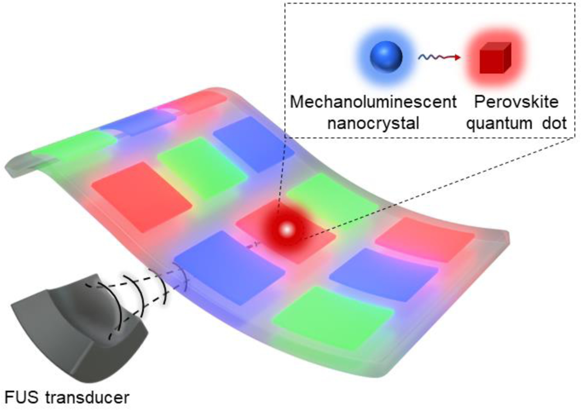
Schematic of the FUS-activated flexible pixel array enabled by energy transfer between the mechanoluminescent nanocrystal and the perovskite quantum dot.
Experimental
Synthesis of SMSO colloids
SMSO colloids were synthesized according to a previously reported biomineral-inspired suppressed dissolution method.9,12 The suppressed dissolution method comprises two steps. In the first step, the bulk SMSO material was prepared via a solid-state reaction. Briefly, 2332.56 mg of SrCO3 (15.8 mmol), 777.04 mg of (MgCO3)4·Mg(OH)2·5H2O (1.6 mmol), 961.28 mg of SiO2 (16 mmol), 8.4 mg of Eu2O3 (0.024 mmol), 29.84 mg of Dy2O3 (0.08 mmol), and 29.66 mg of H3BO3 (0.48 mmol) were added into an agate mortar and thoroughly ground for 1 h. Then the mixed precursor was annealed at 1050 °C for 2 h under 5% H2 in Ar to facilitate a solid-state reaction. The bulk SMSO material was then ball-milled using a high-energy ball mill for 30 min to prepare fresh surfaces for the suppressed dissolution method. In the second step, 2000 mg of ball-milled SMSO powder was added into 240 mL of sodium citrate buffer (0.08 mol/L, pH=6) and stirred at 80 °C for 72 h, yielding kinetically preserved SMSO colloids in the undersaturated environment. Lastly, SMSO colloids were purified by centrifugation at 1000 rpm for 10 min to remove large SMSO particles.
Synthesis of cesium lead halide PQDs
The synthesis of cesium lead halide PQDs begins with the preparation of the Cs-oleate precursor. Specifically, 0.2 g of Cs2CO3 was added into a mixed solution consisting of 0.6 mL of oleic acid (OA) and 7.5 mL of 1-octadecene (ODE). This solution was heated to 200 °C until the Cs2CO3 powder was completely dissolved, yielding the Cs-oleate precursor. Then the Cs-oleate precursor was cooled down to 130 °C and degassed for 30 min. Subsequently, the Cs-oleate precursor was further cooled down to and kept at 80 °C prior to the next step. A hot injection method was used to synthesize PQDs. Specifically, 290 mg of PbBr2 or 368 mg PbI2 or a mixture of both PbBr2 and PbI2 according to a specific molar ratio, 2 mL of OA, 2 mL of oleylamine (OLA), and 20 mL of ODE were added into a round-bottom flask and degassed at 100 °C for 30 min. Then the mixed solution was heated to 160 °C under argon flow, followed by a rapid injection of 1.8 mL of the Cs-oleate precursor solution. The reaction was kept at 160 °C for 5 s and was then quickly quenched by ice water. 60 mL of butanol was added to purify the perovskite QDs. The resulting perovskite QDs were dispersed in toluene for further use.
Synthesis of silica-coated PQDs (PQD@SiO2)
PQD@SiO2 (i.e., CsPbBr3@SiO2, CsPb(Br0.3I0.7)3@SiO2, and CsPbI3@SiO2) was synthesized by following a previously reported method.24 Specifically, 200 μL of tetramethyl orthosilicate (TMOS) and 20 mL of PQDs in toluene (1 mg/mL) were added into a 50 mL round-bottom flask without capping. After stirring for 36 h, the PQD@SiO2 product was precipitated by centrifugation at 8000 rpm for 10 min and then dried at room temperature for further use.
Preparation of the flexible pixel array
5 mg of SMSO colloids and 10 mg of PQD@SiO2 were added into a 200 μL mixture containing the PDMS precursor and curing agent. The ensuing mixture was transferred to a glass mold and degassed for 30 min, followed by curing at 90 °C for 10 min. The ratio of SMSO colloids to PQD@SiO2 was tuned to optimize the wavelength and intensity of mechanoluminescence under FUS. To make the flexible pixel array, blue, green, and red pixels were separately fabricated in 5×5 mm squares containing SMSO colloids alone, SMSO/CsPbBr3@SiO2, and SMSO/CsPb(Br0.3I0.7)3@SiO2, respectively. Multiple pixels of different colors were assembled into a 3×3 pixel array with additional PDMS precursor and curing agent at 90 °C for 10 min, yielding the FUS-activated display.
FUS-activated ML emission in the flexible pixel array
Each pixel on the flexible pixel array was placed at the focus of the FUS. The pixel was charged for 10 s with a 356-nm light-emitting diode (LED) at 0.13 mW/mm2. FUS pulses with a central frequency of 1.5 MHz, an amplitude of 30%, a duty cycle of 20%, and a repetition rate of 1 Hz were immediately applied. ML emission from the FUS focus was simultaneously acquired via a color digital EOS 5D MARK IV camera.
Structural and optical characterizations
X-ray diffraction (XRD) patterns were measured by a PANalytical Empyrean diffractometer. Scanning electron microscope (SEM) images were acquired by an Apreo S LoVac SEM. Transmission electron microscope (TEM) images were captured by a Tecnai TEM. UV-Vis absorption spectra were collected by a Evolution 350 UV-Vis Spectrophotometer. Photoluminescence emission spectra were collected by a Horiba FluoroLog Fluorometer. Mechanoluminescence spectra were measured by a fiber-coupled OCEAN-HDX-VIS-NIR spectrometer.
Results and discussion
In the FUS-addressed display, ML colloids, which are activated by FUS, transfer their photon energy to nearby PQDs to emit different colors determined by the bandgap of the PQD (Fig. 1). Therefore, the first step to realizing the FUS-addressed display is to synthesize ML colloids with short-wavelength emission, sensitive and bright mechanoluminescence under FUS, and small diameter distribution. To this end, we leveraged a recently reported biomineral-inspired suppressed dissolution approach to synthesize colloidal SMSO nanocrystals.9 We first used the solid-state reaction to synthesize bulk SMSO particles with sizes of >10 μm (Fig. 2a). These SMSO bulk particles exhibited bright luminescence under mechanical stress, yet their large sizes prevented their incorporation into a flexible substrate and efficient energy transfer to PQDs. Therefore, we used the suppressed dissolution approach to synthesize SMSO colloids (Fig. 2b) from their precursor bulk particles while preserving the crystallinity and brightness of bulk SMSO. Remarkably, the prepared SMSO nanoparticles exhibit excellent colloidal stability (Fig. 2d) with an average diameter of 40 nm (Fig. 2c). SMSO colloids exhibited photoluminescence centered at 470 nm (Fig. 2e), corresponding to the blue luminescence of the colloidal solution (Fig. 2d,ii). After incorporating the SMSO nanocrystals in a PDMS phantom, the phantom showed strong mechanoluminescence at the focus of the FUS (Fig. 2f), with its mechanoluminescence spectrum well overlapping with the photoluminescence spectrum (Fig. 2e). This result suggests the same luminescent centers at play for both mechanoluminescence and photoluminescence. Importantly, the strong mechanoluminescence of SMSO colloids at 470 nm enables them as a donor of photon energy for efficiently exciting the photoluminescence perovskite QDs.
Figure 2.
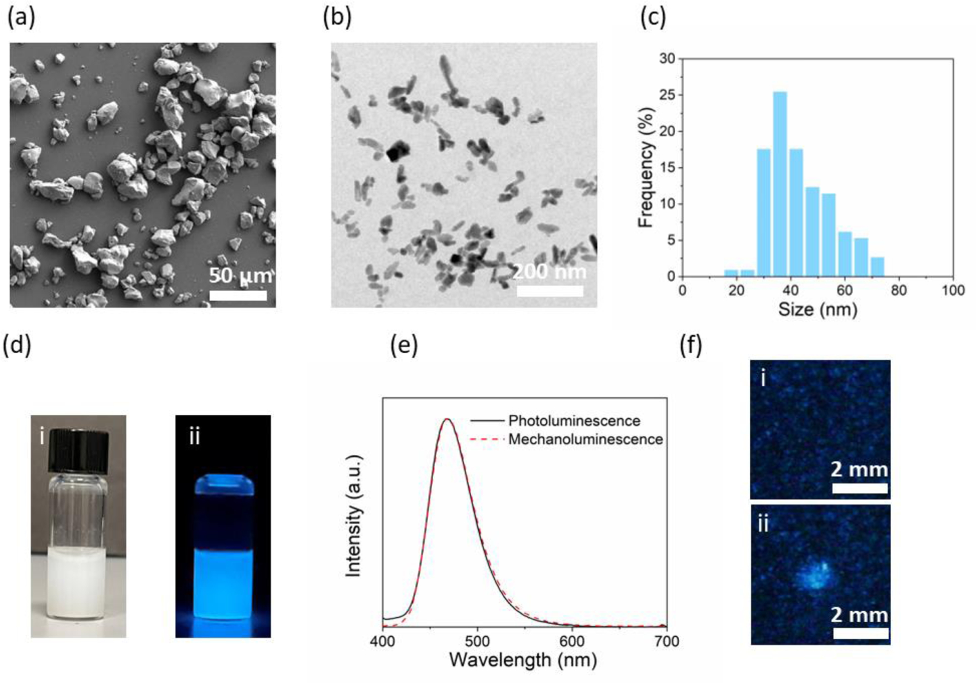
Synthesis and characterizations of SMSO colloids. (a) A representative SEM image of bulk SMSO particles synthesized by a solid-state reaction. (b) A representative TEM image of colloidal SMSO nanocrystals produced by a biomineral-inspired suppressed dissolution approach. (c) Size histogram of colloidal SMSO nanocrystals. (d) Brightfield (i) and luminescence (ii) image of SMSO colloids suspended in water. (e) Photoluminescence and mechanoluminescence spectra of SMSO colloids. (f) Mechanoluminescence images of a PDMS phantom containing SMSO colloids with the FUS off (i) and on (ii).
Having established an intense donor of photon energy under FUS, we next sought to achieve color tuning by synthesizing PQDs as acceptors. To this end, we synthesized three typical inorganic PQDs, CsPbBr3, CsPb(Br0.3I0.7)3, and CsPbI3, which have been reported to have strong absorption at 470 nm and tunable emission in the range of 515–680 nm. All three PQDs exhibit uniform size distributions with an average diameter around 10 nm (Fig. 3a&b). The XRD patterns of these PQDs confirm their monoclinic crystal phase (Fig. 3c), in agreement with the literature.25 Upon UV excitation at 365 nm, the three PQDs display bright photoluminescence with their emission colors ranging from green to red, which are even visible under ambient light (Fig. 3d). The photoluminescence spectra of these PQDs demonstrate sharp emission peaks from 510 nm to 680 nm with an increasing proportion of iodide and a decreasing proportion of bromide (Fig. 3e). The emission tuning phenomenon thus confirms successful bandgap engineering of PQDs by adjusting the halide composition.26 Due to the narrow emission bandwidth (~25 nm), CsPbBr3, CsPb(Br0.3I0.7)3, and CsPbI3 PQDs yield highly saturated green, red, and deep red colors, respectively, resulting in a broader color gamut even than that defined by the NTSC color standard (Fig. 3f). Besides the wide color tunability and sharp emission peaks, the absorption spectra of these PQDs also exhibit similar band edge shifting as the emission spectra (Fig. 3e). Importantly, the strong absorption below 500 nm for all three PQDs makes them ideal acceptors of photon energy from SMSO colloids under FUS.
Figure 3.
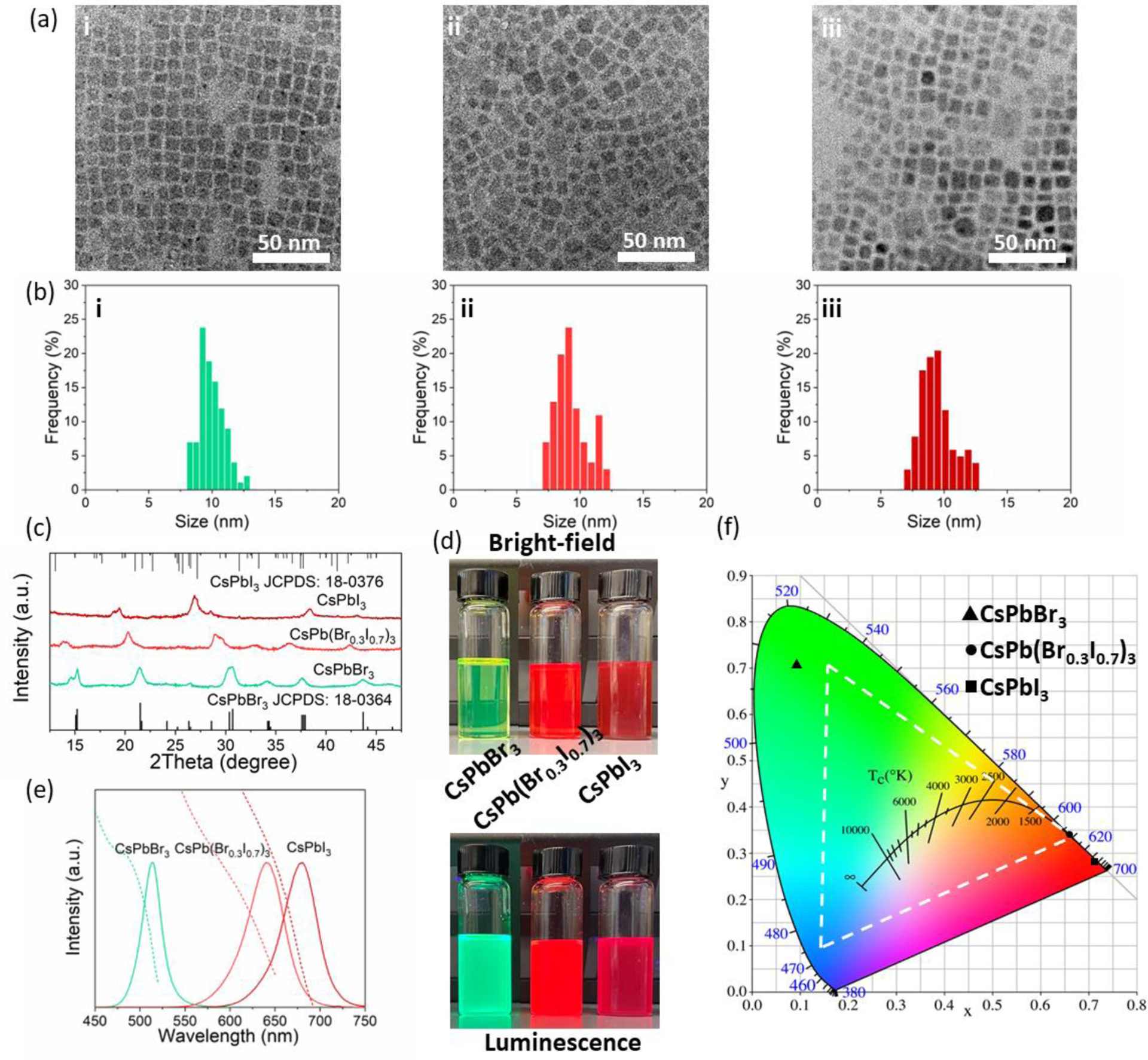
Synthesis and characterizations of cesium lead halide PQDs. (a&b) Representative TEM images (a) and corresponding size distributions (b) of (i) CsPbBr3, (ii) CsPb(Br0.3I0.7)3, and (iii) CsPbI3 PQDs. (c) XRD patterns of CsPbBr3, CsPb(Br0.3I0.7)3, and CsPbI3 PQDs. (d) Brightfield (top) and luminescence (bottom) image of CsPbBr3, CsPb(Br0.3I0.7)3, and CsPbI3 PQDs dispersed in toluene. (e) Absorption (dashed lines) and photoluminescence (solid lines) spectra of CsPbBr3, CsPb(Br0.3I0.7)3, and CsPbI3 PQDs. (f) The International Commission on Illumination (CIE) chromaticity diagram overlaid with the emission color of CsPbBr3, CsPb(Br0.3I0.7)3, and CsPbI3 PQDs. The color gamut defined in the NTSC color standard is highlighted by the white dashed triangle.
Having demonstrated the strong mechanoluminescence of SMSO colloids and tunable photoluminescence of PQDs, we next sought to integrate both of them in a PDMS phantom for tuning of the mechanoluminescence wavelength under FUS. PDMS phantom exhibits excellent transparency (>90% transmittance) across the entire visible spectrum with approximately equal attenuation (<10%) at the emission wavelengths of SMSO, SMSO/CsPbBr3, and SMSO/CsPb(Br0.3I0.7)3 (Fig. S1). Therefore, the encapsulation of these materials in PDMS results in negligible attenuation and distortion of the emission intensity and color, respectively, under FUS stimulation. Since PQDs are sensitive to moisture, we first encapsulated them with a silica coating to preserve their luminescence properties when used in a FUS-addressed display. The quantum yields (QYs) of CsPbBr3@SiO2 and CsPb(Br0.3I0.7)3@SiO2 were measured as 78% and 51%, respectively (Fig. S2). In addition, since the organic ligands on the surface of PQDs prevent the curing of the PDMS phantom, replacing the organic ligands with silica coating also facilitates their incorporation in the pixel display. Specifically, we used SMSO/CsPbBr3@SiO2 and SMSO/CsPb(Br0.3I0.7)3@SiO2 to prepare green and red pixels owing to their bright green and red emission stimulated by FUS (Fig. 4a). In contrast, we excluded the SMSO/CsPbI3 pair in the pixels due to its emission in the deep red (center wavelength ~680 nm), thus becoming insensitive to the human eye.27
Figure 4.
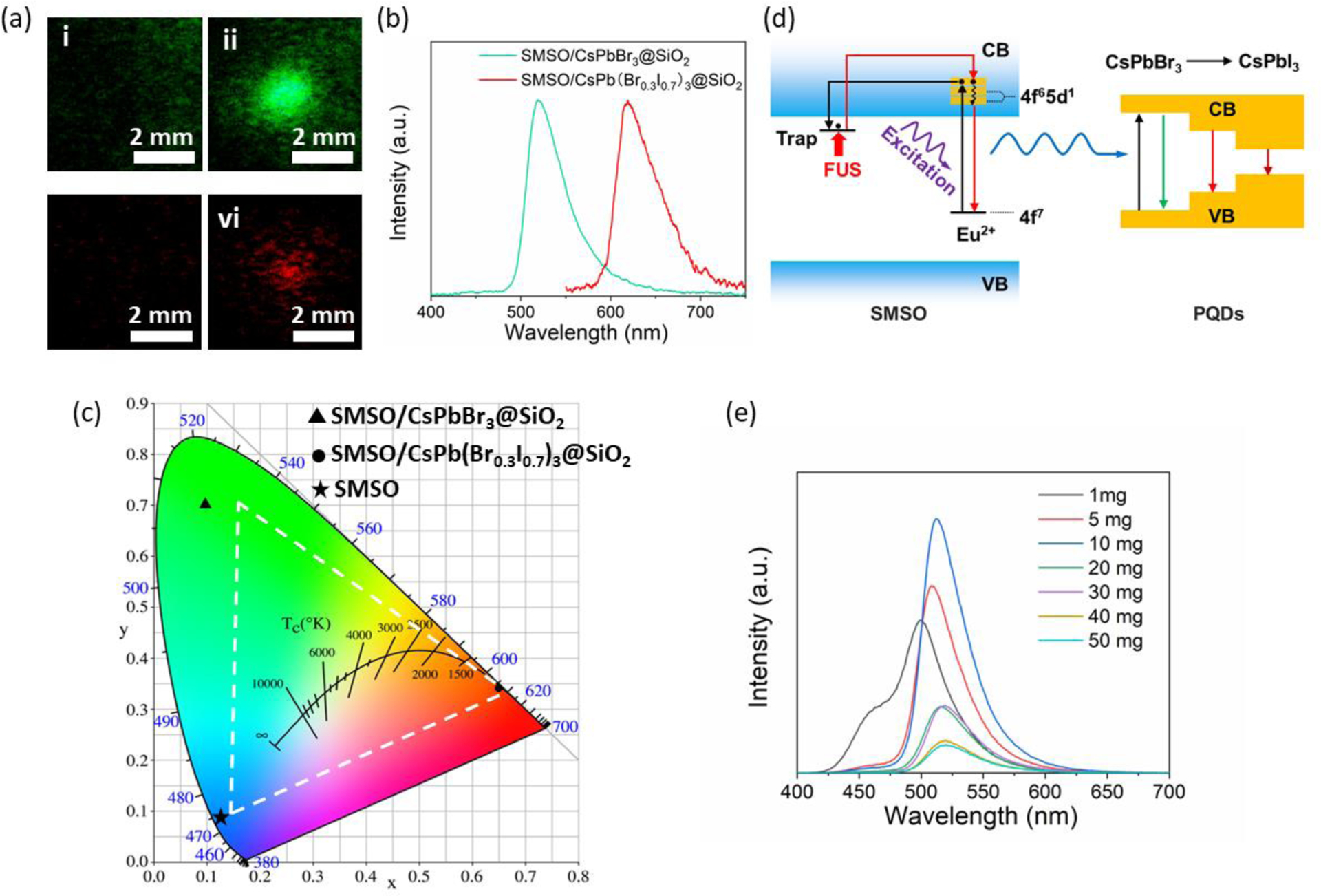
Color tuning of the SMSO/PQD composites. (a) Representative mechanoluminescence images of SMSO/CsPbBr3@SiO2 (i,ii) and SMSO/CsPb(Br0.3I0.7)3@SiO2 composites (iii,iv) in PDMS phantoms when FUS is off (i,iii) and on (ii,vi). (b) Mechanoluminescence spectra of SMSO/CsPbBr3@SiO2 and SMSO/CsPb(Br0.3I0.7)3@SiO2 composites in PDMS phantoms. (c) CIE chromaticity diagram of the mechanoluminescence emission color of PDMS phantoms containing SMSO alone, SMSO/CsPbBr3@SiO2, and SMSO/CsPb(Br0.3I0.7)3@SiO2. The color gamut defined in the NTSC color standard is highlighted by the white dashed triangle. (d) The proposed schematic of FUS-induced mechanoluminescence tuning through energy transfer between SMSO and PQDs. VB: valence band; CB: conduction band. (e) The afterglow spectra of SMSO/CsPbBr3@SiO2 phantoms with the amount of SMSO colloids fixed at 5 mg and various amounts of CsPbBr3@SiO2 PQDs in the range from 1 mg to 50 mg.
We characterized the mechanoluminescence spectra from the PDMS pixels containing SMSO/CsPbBr3@SiO2 and SMSO/CsPb(Br0.3I0.7)3@SiO2 with several important findings (Fig. 4b). First, despite the presence of SMSO colloids in these PDMS pixels, the characteristic peak of SMSO at 470 nm (cf. Fig. 2e) is completely absent in the mechanoluminescence spectra of both pixels. This absence suggests efficient energy transfer between the SMSO donor and the PQD acceptor, yielding pure emission color solely determined by the bandgap of the PQD. Second, compared to the photoluminescence spectra of PQDs (Fig. 3e), the mechanoluminescence spectra of corresponding SMSO/PQD pixels exhibit a slight increase of the bandwidth (~35 nm). To find out the cause of this increased bandwidth, we characterized the photoluminescence spectra of PQD@SiO2 alone (Fig. S3) and observed a similar level of peak broadening (~35 nm). We thus attribute this peak broadening to the increased damping of the resonance as a result of the interaction between PQDs with the silica.28 Third, despite the broader emission peaks, the mechanoluminescence color gamut (Fig. 4c) of SMSO/CsPbBr3@SiO2 and SMSO/CsPb(Br0.3I0.7)3@SiO2 PDMS pixels is still wider than the NTSC color standard. Combining the mechanoluminescence of a SMSO-only pixel, the highly-saturated RGB colors of all PDMS pixels highlight their potential use in a flexible pixel display.
To understand the emission process and color tunability of the SMSO/PQD composites, we propose an energy transfer mechanism based on their specific band diagrams (Fig. 4d). Specifically, upon UV irradiation, the Eu2+ dopant in SMSO is excited to promote an electron to the conduction band of SMSO. This electron, acting as a charge carrier in the conduction band, quickly becomes captured by electron traps, such as and .9 The FUS stimulus releases the trapped electron, which then returns to the ground state of Eu2+ and releases its energy in the form of light emission. The emitted photon energy may be transferred radiatively or non-radiatively, depending on the distance between the SMSO donor and PQD acceptor, to the PQD, exciting its photoluminescence in the form of lower-energy (i.e., longer-wavelength) photons. The efficient energy transfer is validated by the disappearance of 470 nm emission in the mechanoluminescence spectra of the SMSO/PQD composites (Fig. 4b). To validate the energy transfer between the SMSO donor and PQD acceptor, we fixed the amount of SMSO while varying that of CsPbBr3@SiO2 in each PDMS pixel. We found that the emission intensity at 470 nm gradually decreased with the increase in the amount of CsPbBr3@SiO2 In the meantime, the emission peak at 515 nm gradually increased before it started to decline, potentially due to self-quenching (Fig. 4e). These results confirm efficient energy transfer between SMSO colloids and PQDs at an appropriate ratio and concentration in the pixel.
The efficient energy transfer and bright, tunable emission of SMSO/PQD@SiO2 composites encouraged us to prepare a pixel array composed of RGB colors as a FUS-activated display (Fig. 5a). This 3×3 array comprises pixels that contain SMSO colloids alone, SMSO/CsPbBr3@SiO2, or SMSO/CsPb(Br0.3I0.7)3@SiO2 in PDMS (Fig. 5b). Despite the weak afterglow from each pixel (Fig. 5c and Fig. S4), this pixel array is negligibly impacted by the afterglow and shows discernible emission at the focus of impinging ultrasound, with its color corresponding to the mechanoluminescence spectrum of the constituting materials of the activated pixel (Fig. 5d). Since the pixel array is wirelessly addressed by FUS, by scanning the focus of ultrasound across all pixels, we observe different RGB colors corresponding to the specific pixel under FUS activation (Fig. 5e), thus fulfilling the role of this pixel array as a multicolor display. Although the current pixel (~5 mm) exceeds the focus size of ultrasound, we envision the theoretical pixel resolution can approach ~100 μm for a high-resolution display addressed by a 10-MHz ultrasound transducer. Lastly, we demonstrate the excellent flexibility of this multicolor display owing to the small, <50 nm sizes of its constituting SMSO and PQD nanocrystals and the use of PDMS elastomer as the matrix for each pixel. Remarkably, even in the presence of significant bending (Fig. 5f), this pixel array still exhibits its location-dependent emission under FUS stimulation (Fig. 5g–i). We found consistent emission under FUS at a bending angle up to 90॰, thus suggesting minimal effect of bending on the energy transfer and illumination of the ML colloids (Fig. S5). Taken together, these results suggest the potential of the pixel array as a flexible and wirelessly activated display for wearable electronic and photonic applications.
Figure 5.
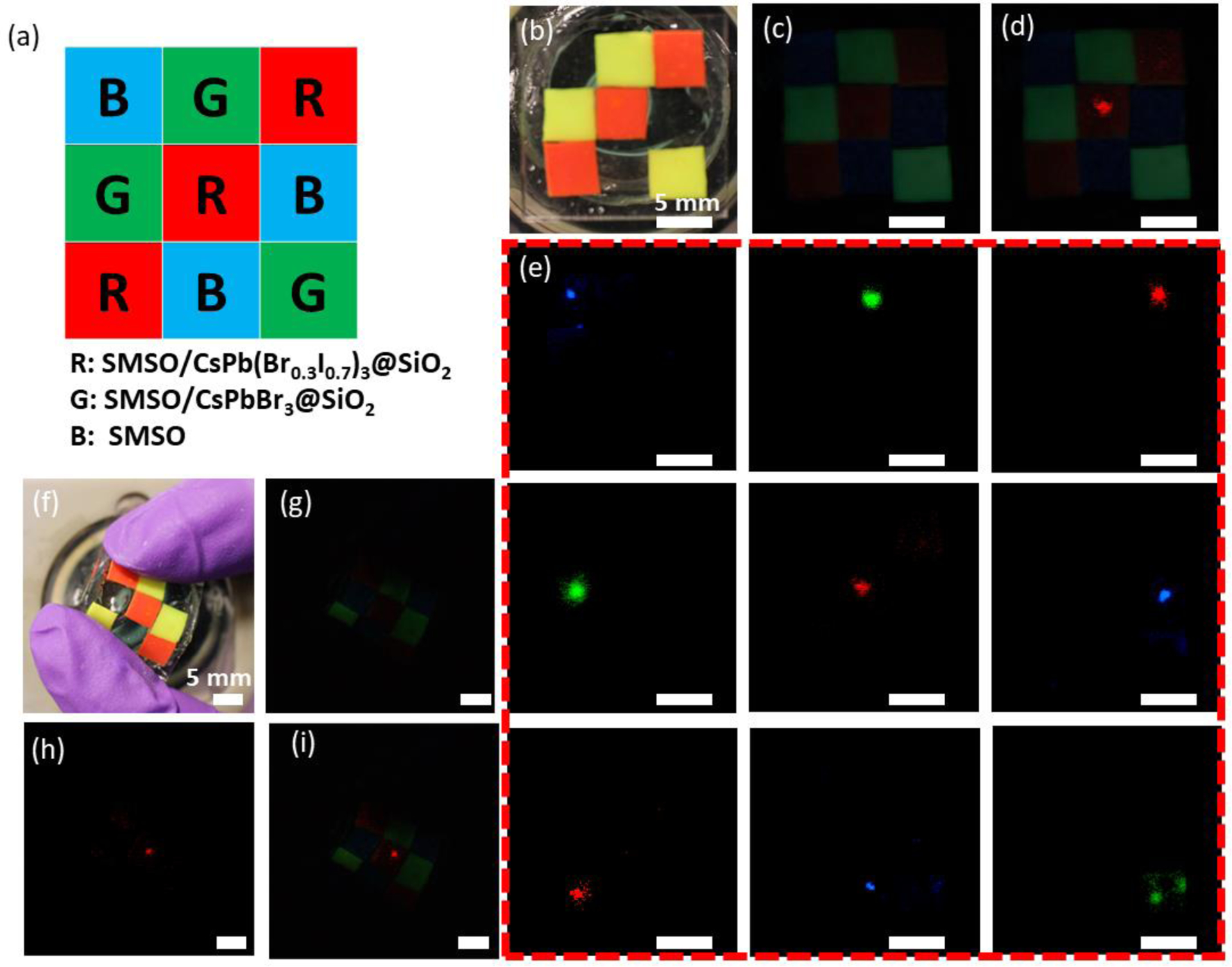
A FUS-activated, flexible multicolor display enabled by color-tunable mechanoluminescence. (a) Schematic of a full-gamut 3×3 array with three primary colors: blue (SMSO colloids alone), green (SMSO/CsPbBr3@SiO2 composites), and red (SMSO/CsPb(Br0.3I0.7)3@SiO2 composites). (b) Brightfield photograph of a 3×3 array made of pixels containing SMSO colloids alone, SMSO/CsPbBr3@SiO2 composites, and SMSO/CsPb(Br0.3I0.7)3@SiO2 composites. (c) Afterglow image of the pixel array shown in b. (d) An overlay of the afterglow image with the mechanoluminescence image, the latter of which was taken when FUS was focused at the central pixel of the array. (e) Mechanoluminescence images of the pixel array when FUS is focused at each of the 9 pixels. (f) Brightfield photograph of the array under bending. (g) Afterglow image of the pixel array shown in f. (h) Mechanoluminescence image of the bent pixel array when FUS is focused at the central pixel of the array. (i) An overlay of the afterglow image in g with the mechanoluminescence image in h.
Conclusion
In this paper, we present the proof-of-concept demonstration of the first flexible and FUS-addressable multicolor display enabled by ML colloids with strong blue mechanoluminescence and PQDs with wide color tunability. Specifically, the flexibility of this display is facilitated by the small sizes of the constituting nanocrystals, which are well suspended and uniformly integrated into the elastomeric matrix of each pixel in the display. Unlike conventional LED displays that require wired powering and addressing of each pixel, this prototyped display can be wirelessly addressed and activated by scanning FUS, thus minimizing its footprint even with significant multiplexing. Furthermore, the color tunability of this display is enabled by the tunable photoluminescence of cesium lead halide PQDs, which act as acceptors to receive the mechanoluminescence energy from the ML colloids. Remarkably, the color gamut of this prototype display under FUS exceeds the NTSC color standard, thus validating the utility of the display to synthesize the full range of hues from the three primary colors. We anticipate that future developments of the FUS-activated display will leverage the focusing and scanning capabilities of ultrasound, thus significantly increasing the spatial resolution and multiplexity of the display. Despite the large pixel size (~5 mm) in our prototype, the theoretical pixel resolution can be as small as the diffraction-limited focal spot size of ultrasound well below 1 mm (depending on the frequency of FUS). The FUS-addressed multicolor emitter system may open up a new avenue towards wearable electronics and photonics by realizing a flexible, wireless, and standalone display interface.
Supplementary Material
Acknowledgement
Part of this work was performed at the Stanford Nano Shared Facilities (SNSF), supported by the National Science Foundation under award ECCS-2026822. G.H. acknowledges three awards by NIH (5R00AG056636-04, 1R34NS127103-01, and R01NS126076-01), a National Science Foundation (NSF) CAREER Award (2045120), an NSF EAGER Award (2217582), a Rita Allen Foundation Scholars Award, a Beckman Technology Development Grant, a grant from the focused ultrasound (FUS) Foundation, a gift from the Spinal Muscular Atrophy (SMA) Foundation, a gift from the Pinetops Foundation, two seed grants from the Wu Tsai Neurosciences Institute, and two seed grants from the Bio-X Initiative of Stanford University. X.W. acknowledges the support by a Stanford Graduate Fellowship.
References
- 1.Feng A and Smet APF, Materials, 2018, 11, 484. [DOI] [PMC free article] [PubMed] [Google Scholar]
- 2.Zhang J-C, Wang X, Marriott G and Xu C-N, Prog. Mater Sci, 2019, 103, 678–742. [Google Scholar]
- 3.Terasaki N, Xu C-N, Li C, Zhang L, Li C, Ono D, Tsubai M, Adachi Y, Imai Y, Ueno N and Shinokawa T, in Health Monitoring of Structural and Biological Systems 2012, ed. Kundu T, 2012, vol. 8348, p. 83482D. [Google Scholar]
- 4.Liu L, Xu C-N, Yoshida A, Tu D, Ueno N and Kainuma S, Advanced Materials Technologies, 2019, 4, 1800336. [Google Scholar]
- 5.Zhang Y, Fang Y, Li J, Zhou Q, Xiao Y, Zhang K, Luo B, Zhou J and Hu B, ACS Appl. Mater. Interfaces, 2017, 9, 37493–37500. [DOI] [PubMed] [Google Scholar]
- 6.Zhao Y, Gao W, Dai K, Wang S, Yuan Z, Li J, Zhai W, Zheng G, Pan C, Liu C and Shen C, Adv. Mater, 2021, 33, e2102332. [DOI] [PubMed] [Google Scholar]
- 7.Hyodo K, Terasawa Y, Xu C-N, Sugaya H, Mishima H and Miyakawa S, J. Biomech, 2012, 45, S263. [Google Scholar]
- 8.Wu X, Zhu X, Chong P, Liu J, Andre LN, Ong KS, Brinson K Jr, Mahdi AI, Li J, Fenno LE, Wang H and Hong G, Proc. Natl. Acad. Sci. U. S. A, 2019, 116, 26332–26342. [DOI] [PMC free article] [PubMed] [Google Scholar]
- 9.Yang F, Wu X, Cui H, Jiang S, Ou Z, Cai S and Hong G, J. Am. Chem. Soc, 2022, 144, 18406–18418. [DOI] [PMC free article] [PubMed] [Google Scholar]
- 10.Hong G, Science, 2020, 369, 638. [DOI] [PMC free article] [PubMed] [Google Scholar]
- 11.Wang X, Zhang H, Yu R, Dong L, Peng D, Zhang A, Zhang Y, Liu H, Pan C and Wang ZL, Adv. Mater, 2015, 27, 2324–2331. [DOI] [PubMed] [Google Scholar]
- 12.Yang F, Wu X, Cui H, Ou Z, Jiang S, Cai S, Zhou Q, Wong BG, Huang H and Hong G, Sci Adv, 2022, 8, eabo6743. [DOI] [PMC free article] [PubMed] [Google Scholar]
- 13.Hinchet R, Yoon H-J, Ryu H, Kim M-K, Choi E-K, Kim D-S and Kim S-W, Science, 2019, 365, 491–494. [DOI] [PubMed] [Google Scholar]
- 14.Masterson V, Feel the metaverse with your bare hands – using ultrasonic waves, https://www.weforum.org/agenda/2022/05/metaverse-vr-ultrasonic-tech-emerge/, (accessed 31 October 2022).
- 15.Suzuki S, Inoue S, Fujiwara M, Makino Y and Shinoda H, IEEE Trans. Haptics, 2021, 14, 740–749. [DOI] [PubMed] [Google Scholar]
- 16.Wong M-C, Chen L, Bai G, Huang L-B and Hao J, Adv. Mater, 2017, 29, 1701945. [DOI] [PubMed] [Google Scholar]
- 17.Jeong SM, Song S, Lee S-K and Ha NY, Adv. Mater, 2013, 25, 6194–6200. [DOI] [PubMed] [Google Scholar]
- 18.Du Y, Jiang Y, Sun T, Zhao J, Huang B, Peng D and Wang F, Adv. Mater, 2019, 31, e1807062. [DOI] [PubMed] [Google Scholar]
- 19.Lin K, Xing J, Quan LN, de Arquer FPG, Gong X, Lu J, Xie L, Zhao W, Zhang D, Yan C, Li W, Liu X, Lu Y, Kirman J, Sargent EH, Xiong Q and Wei Z, Nature, 2018, 562, 245–248. [DOI] [PubMed] [Google Scholar]
- 20.Zheng W, Huang P, Gong Z, Tu D, Xu J, Zou Q, Li R, You W, Bünzli J-CG and Chen X, Nat. Commun, 2018, 9, 3462. [DOI] [PMC free article] [PubMed] [Google Scholar]
- 21.Ou X, Qin X, Huang B, Zan J, Wu Q, Hong Z, Xie L, Bian H, Yi Z, Chen X, Wu Y, Song X, Li J, Chen Q, Yang H and Liu X, Nature, 2021, 590, 410–415. [DOI] [PubMed] [Google Scholar]
- 22.Wang Y, Li X, Song J, Xiao L, Zeng H and Sun H, Adv. Mater, 2015, 27, 7101–7108. [DOI] [PubMed] [Google Scholar]
- 23.Swarnkar A, Marshall AR, Sanehira EM, Chernomordik BD, Moore DT, Christians JA, Chakrabarti T and Luther JM, Science, 2016, 354, 92–95. [DOI] [PubMed] [Google Scholar]
- 24.Huang S, Li Z, Kong L, Zhu N, Shan A and Li L, J. Am. Chem. Soc, 2016, 138, 5749–5752. [DOI] [PubMed] [Google Scholar]
- 25.Sun Q, Ni C, Yu Y, Attique S, Wei S, Ci Z, Wang J and Yang S, J. Mater. Chem, 2018, 6, 12484–12492. [Google Scholar]
- 26.Song J, Li J, Li X, Xu L, Dong Y and Zeng H, Adv. Mater, 2015, 27, 7162–7167. [DOI] [PubMed] [Google Scholar]
- 27.Bowmaker JK and Dartnall HJ, J. Physiol, 1980, 298, 501–511. [DOI] [PMC free article] [PubMed] [Google Scholar]
- 28.Hempe M, Kukhta NA, Danos A, Fox MA, Batsanov AS, Monkman AP and Bryce MR, Chem. Mater, 2021, 33, 3066–3080. [DOI] [PMC free article] [PubMed] [Google Scholar]
Associated Data
This section collects any data citations, data availability statements, or supplementary materials included in this article.


