

Abstract
Traveling wave ion mobility experiments using planar electrode structures (e.g., structures for lossless ion manipulation, TW-SLIM) leverage the mature manufacturing capabilities of printed circuit boards (PCBs). With routine levels of mechanical precision below 150 microns, the conceptual flexibility afforded by PCBs for use as planar ion guides is expansive. To date, the design and construction of TW-SLIM platforms require considerable legacy expertise, especially with respect to simulation and circuit layout strategies. To lower the barrier of TW-SLIM implementation, we introduce Python-based interactive tools that assist graphical layout of the core electrode footprints for planar ion guides with minimal user inputs. These scripts also export exact component locations and assignments for direct integration into KiCad and SIMION for PCB finalization and ion flight simulations. The design concepts embodied in the set of scripts comprising SLIM Pickins (PCB CAD generation) and pigsim (SIMION workspace generation) build upon the lessons learned in the independent development of the research-grade TW-SLIM platforms in operation at WSU. Due to the inherent flexibility of the PCB manufacturing process and the time devoted to board layouts prior to manufacturing, both scripts serve to enable rapid, iterative design considerations. Because only a few pre-defined parameters are necessary (i.e., the TW-SLIM monomer width, x position following a TW Turn, and y position following a TW Turn) it is possible to design the exact component layouts and accompanying simulation space in a manner of minutes. There is no known limitation to the board layout capacities of the scripts, and the size of a designed layout is ultimately constrained by the abilities of the final PCB design and simulation tools, KiCad and SIMION, to accommodate the thousands of electrodes comprising the final design (i.e. RAM and software overhead). Toward removing the barriers to exploring new SLIM tracks and the likelihood of layout errors that require considerable revision and engineering time, the SLIM Pickins and pigsim tools (included as Supporting Information) allow the user to quickly design a length of planar ion guide, simulate its abilities to confine and transmit ions, compare hypothetical board outlines to given vacuum chamber dimensions, and generate a near-production ready PCB CAD file. In addition to these tools, this report outlines a series of cost-saving strategies with respect to vacuum feedthroughs and vacuum chamber design for TW ion mobility experiments using planar ion guides.
Keywords: Instrument Design, Ion Mobility, Ion Guide, SLIM, Simulation
Introduction
High-resolution gas-phase separations across extremely long pathlengths using planar ion guides (e.g., structures for lossless ion manipulation (SLIM)) are achieved through the adequate confinement of ions in the radial dimension and the digital manipulation across the axial or serpentine pathway.1 Compared to drift cell technologies, comparatively low voltage, alternating current (AC) waveforms are employed for ion separations, directly facilitating near-infinite pathlengths for separation.2–4 This feature has been used to demonstrate exceptional resolution gains in relative mobility separations, allowing disambiguation of isomeric species which are conflated by mass analyzers.3,5,6 Additionally, isotopologues, or chemical species differing only by isotopic mass differences, have been resolved over pathlengths exceeding two kilometers in 1.5 torr of purified argon gas.7 Though isotopes/isotopologues are readily resolved by mass spectrometers, their separation at relatively higher pressures offers to extend isotope-labeling strategies to mobility separations, amongst other novelties.8
SLIM separations are logically complemented by mass spectrometry, and the ability to deftly manipulate ions further extends the analytical utility of the hybrid instrumental technique. A novel system constructed by researchers at EPFL couples a multipass SLIM IMS system with a TOF-MS, but importantly can also direct ions to a cryogenic trap where they are stored for messenger tagging vibrational spectroscopy.9–11 Performing collision-induced dissociation of ions in switchable subsections of the SLIM before passing to the cryo-IR module enables specific fragmentation analysis and increases structural knowledge generally.11,12 Additionally, binary multiplexing strategies have been explored on this instrument, drastically increasing the rate of spectroscopic fingerprinting for mobility-selected species.13,14 To date, few research academic groups have independently realized functioning TW-SLIM experiments.15–17 The impressive performance of TW-SLIM demonstrates its potential for both analytical and preparative separations. Consequently, broader access to development resources is needed to facilitate experimentation.
Building upon key developments within the field and in our own laboratory,2,3,11,17,18 this report details a tractable set of design, simulation, and implementation tools that enhance the pace of scientific discovery and development using the concepts embodied within the SLIM platform. Specifically, the tools described include an interactive graphical design framework that directly integrates into an iterative workflow that includes python,19 SIMION,20,21 and KiCad.22 Given the inherent flexibility when using planar ion guides and printed circuit boards (PCB), the tools do not focus on a single design but the framework for researchers to rapidly incorporate the exceptional separation and ion transport capability into their respective research programs. The python-based tools (i.e., pigsim and SLIM Pickins) and salient usage examples are included in the Supporting Information and housed on github (https://github.com/bhclowers). In addition to computational tools, we include lessons learned in the development of multiple, distinctly different SLIM platforms with respect to vacuum chamber design and management, along with PCB-based designs as electrical feedthroughs.
Overview of Planar Ion Guides
To provide a graphical overview of the ion confining capacity of SLIM, Figure 1c includes the range of waveforms that are often applied across the two mirrored SLIM surfaces. To create the field necessary for ion confinement, these boards are folded along the axis of mirror symmetry and spaced approximately 2.5 – 3.5 mm apart. Applying a series of RF waveforms (~0.5 – 1 MHz, 100–300 Vpp) to the longitudinally arranged, unsegmented electrodes prevents ions from neutralizing on the board surfaces.23 Static DC guard electrodes are also important as they aid in pressing ions toward the center of the SLIM axis. Combined, the guard and RF electrodes create a semi-quadrupolar confinement field.18,24 To realize the axial movement of ions using the traveling wave (TW) concept, the dynamic voltages needed for ion movement (i.e., AC waveforms) are applied through the digital manipulation of the DC electrodes. These waveforms can vary with respect to duty cycle and amplitude (e.g., 10–20 kHz and up to 30 Vpp).25,26 Interestingly, the difference between the small board shown in Figure 2 and realizing separation pathlengths that extend beyond 100 meters is conceptually trivial as the underlying set of TW electrodes is grouped in sets of 8 and serves as monomeric units that are extended to realize the pathlengths and ion storage chambers for practical experimentation. While efforts are underway to commercialize the SLIM technology, these endeavors trail behind the academic implementations of SLIM as they lack multi-pass technology,27 on-board CID,12,28 and the flexibility to alter RF frequency rapidly.
Figure 1.
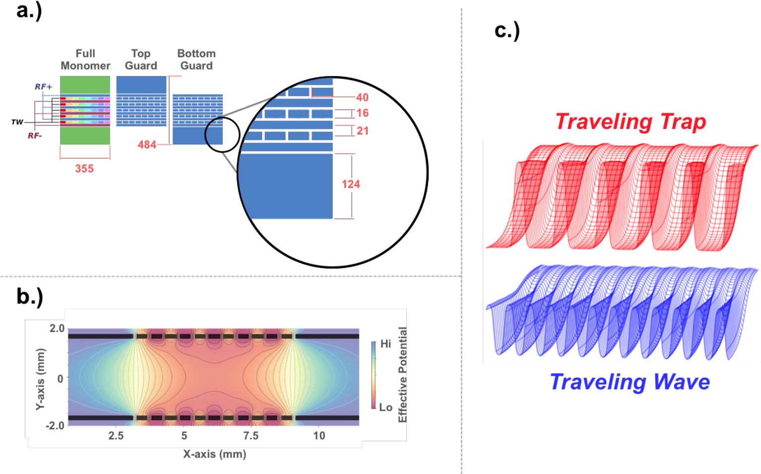
a.) Provides a graphical overview of the standard 6:5 TW-SLIM arrangement with 6 RF rails (i.e., two pairs of 3) and 5 TW sets, each with 8 electrodes. The dimensions shown are in mils (i.e., 0.001”), and the spacing between all electrodes is in 5 mils. When accounting for the spacing between electrodes, the total length of each monomer is 360 mils. A KiCad library for these footprints is found in the Supporting Information. b.) The simulated electric fields within a planar ion guide using the electrode arrangements shown in a.). For display purposes, the effective potential was scaled. c.) Shows a cross-section of example waveforms that may be applied to the TW electrodes. The upper red waveform mesh corresponds to a traveling trap with a 10000000 configuration where 1 is the high state, and the blue mesh corresponds to a lower voltage, higher speed traveling wave with a profile of 11110000.
Figure 2.
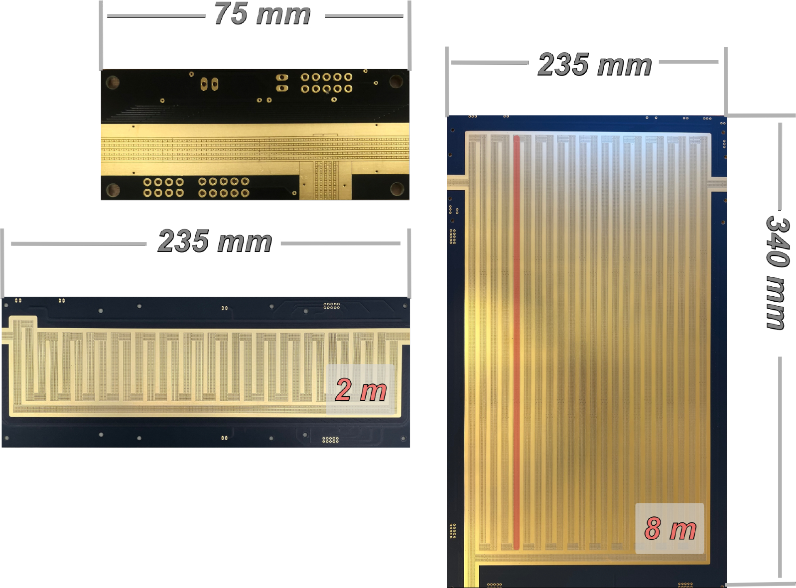
Representative board configurations demonstrating the transition from simple TW structures to complex variants with multi-pass and CRIMP capabilities. While routing very short boards manually is feasible, the placement of the electrodes for boards, even at 2 m, becomes resource-intensive and error-prone. The development and layout of the 2 m and 8 m boards shown were accomplished using the SLIM Pickins tool described.
A representative sample of the suite of different SLIM designs realized at WSU for research purposes is shown in Figure 2. The largest board consists of an 8-meter, cyclic SLIM path that includes multiple separate TW tracks that leverage the newly designed, low-cost drive electronics that lower the barriers to achieving the range of functionality needed for the broader adoption and integration of SLIM platforms in molecular analysis campaigns. Overlaid and highlighted in red on the photo of the 8 m board is the approximate physical length of an ion population with a temporal width of ~2–3 ms at the baseline.1,3 With axial ion velocities of ~100 m/s, the physical separation of a diffuse ion population can be considerable and extend for 10s of cm. For this reason, broadband separations of ions using cyclic TW technologies require extended pathlengths to mitigate the lapping effect for unknown ion populations.29,30 It is also worth noting that judicious mechanical alignment of separate boards is often sufficient to couple different boards and capabilities within the TW-SLIM environment. The potential to mechanically align disparate board sets largely mirrors the original DC-only axial fields used in early SLIM reports. Our experience has been that aligning TW-SLIM tracks between boards is exceedingly forgiving and offers a strategy to minimize costs when rapidly exploring new ion guide prototypes.31
Physical and Materials Selection.
The planar ion guides that comprise the broader SLIM environment are commonly produced using the design and manufacturing infrastructure focused on PCB technologies. The exquisite levels of design flexibility, reproducibility, and mechanical precision of PCB manufacturing are well-suited to the field of analytical chemistry.32 Concerning gas-phase cleanliness, select materials for producing PCBs (e.g., FR-4) are not necessarily ideal.33 However, these concerns are minimized with proper cleaning protocols (e.g., solvent washes and vacuum degassing). Moreover, concerns of this nature can be mitigated using higher-cost materials such as ceramic and PTFE-impregnated PCB material (e.g., Rogers and associated PCB substrates). It is also important to recognize that SLIM experiments to date fall within the 1–10 torr range, which further mitigates outgassing issues. While the PCB may serve as the primary source of potential contamination, the choice of wiring, electrical feedthroughs, and insulating materials also have a significant bearing on the chemical cleanliness of the system. Recognizing that cost is a factor for most experimentalists, polyimide-coated wire or PTFE-coated wire may unnecessarily add costs without reducing the complexity of the experiment. It has been our experience that fluorinated ethylene propylene (FEP) wire and polybutylene terephthalate (PTB, e.g., IDC) or polyethylene terepthalate (PET, e.g., Molex SL) connectors minimize costs, demonstrate favorable outgassing characteristics, and are widely available.33,34 Electroless nickel immersion gold (ENIG) surface finish is commonly used for SLIM systems to minimize electrode oxidation and is widely compatible with common cleaning procedures.35 This finish is shown on all of the boards in Figure 2.
Drive and Control Electronics.
In its current embodiment, the SLIM platform requires a minimum of 9 DC (8 TW electrode sets and 1 guard rail) connections and 2 RF connections. Because the monomers are linked to form the larger board, the TW can be driven by modulating 8 separate power supplies based upon a user-defined waveform or using a single power supply gated into each electrode set.17,36 As with many experimental decisions, the tradeoff between these approaches falls into the categories of costs and complexity. The platform introduced by Kinlein et al. focuses on the ease of implementation of a low-cost square waveform generator while delivering waveforms through 8-independent DC channels offers a wider range of flexibility.17,37 To date, all known implementations of the SLIM experiment, aside from the report by Kinlein et al., leveraged the modular instrumental power supply (MIPS) environment offered by GAA Custom Electronics (Kennewick, WA).13,17,37 There is growing experimental evidence that prompts questions regarding waveform selection and the range of electric fields produced within the SLIM device that supports the continued development of a multi-channel TW supply;26 however, their utility remains as low-cost solutions for TW delivery.
Compared to multipole ion guides, the extended pathlengths and surface area of the SLIM boards create electrode arrangements that can easily produce capacitances in the single-digit nanofarad regime. For these reasons, tailored RF drives are required to deliver the requisite frequencies and RF Vpp. While beyond the scope of this report, there is merit in the flexibility of RF delivery to accommodate a range of analytes. Reports by Schwarz and Bollen focused on ion carpets provide a sound foundation to explore the range of RF conditions needed to stabilize ion motion.38–40 While the choice of TW parameters and guard voltages impact ion stability within the planar ion guide, increasing frequency is often required to stabilize lower m/z ion populations. When viewed as a complete circuit, the planar ion guides that comprise a SLIM setup contain multiple sources of capacitance that contribute directly to the relationship shown in Equation 1, where is the resonant frequency, is the inductance, and is the overall capacitance.
| Eqn. 1 |
Resonate circuits used for ion confinement have the advantage of requiring less power to reach the desired voltages compared to a standard RF power amplifier but are restricted to a narrow band of frequencies under which the drive operates. Drives with inductances in the single to 10s of μH are common for SLIM RF drivers. When coupled with long pathlength boards with capacitances between phases of ~2 nF, RF drive powers up to ~100 Watts are not uncommon. Most of this power is dissipated in the RF head, coil, and wiring; however, care is warranted with respect to the trace widths used during PCB design, the impact of PCB material selection (e.g., FR4 vs. Rogers materials), and minimizing cable lengths between RF driver and the SLIM boards. Readers are also cautioned to consider the stack-up distances between different copper layers when using multi-layer boards, as these design decisions will directly impact the capacitances between the TW and RF tracks. Interestingly, physical heating of the boards shown in Figure 2 when powered (i.e., 875 kHz and 300 Vpp), was not observed using an IR camera. However, maximizing RF trace width and judicious placement of the boards within the vacuum chamber promise to minimize any physical board heating. It is also worth noting that each board that comprises a SLIM set (i.e., top vs. bottom) can be driven independently by matched RF heads to minimize the power requirement for a single RF drive. While customized solutions are possible, the predominance of documented SLIM experiments uses RF supplies provided by GAA Custom Electronics.
Ion Trajectory Simulation Workflow.
Often attributed to the statistician George E.P. Box, the adage “all models are wrong, but some are useful” certainly holds for applying SIMION to the SLIM experiment.41 It is important to note that the outlined SLIM modeling framework does not include gas flow, fringing fields, or any dynamic clustering behavior that may occur within the apparatus. Nevertheless, using SIMION as a design aid provides researchers with a reasonable approximation of possible outcomes.42 In other words, a SIMION model can contribute to the researcher’s understanding of the dynamic and static electric fields that support stable ion motion within the SLIM apparatus. With these caveats stated, the following description outlines a tool (i.e., pigsim) for the graphical layout of planar ion guides using the Python language using a parameterized workspace that allows for the facile creation of gem files directly compatible with SIMION.
It has been our experience that emerging tools to simulate ion motion for ion mobility experiments can be overly complex, commercial options are often expensive, do not necessarily reasonably parameterize ion-neutral collisions, and require continued development to yield results that are comparable to SIMION. While SIMION contains many well-established simulation routines, its user interface and API require considerable expertise to leverage its full capability. It is for these reasons that we have adopted the use of the interactive jupyter environment using Python that allows users to rapidly develop and view potential SLIM electrode arrangements prior to accessing SIMION.
The simulation framework included in the Supporting Information focuses on generating individual subroutines that generate individual SLIM monomers. Looping a constructor makes it possible to generate a SLIM model of considerable size. Out of convenience, our approach defines electrode geometries, including rectangular and polygon shapes, that are defined on a per-pixel basis. Disallowing fractional units allows for the direct mapping of electrode structures developed in Python to the individual grid units in SIMION. It is recognized that newer versions of SIMION can handle fractional units; however, to avoid confusion and streamline the modeling effort, integer units to define the SLIM monomer are used.20
Figure 3a outlines the general workflows of monomer definitions, graphical evaluation, and steps toward SIMION integration. The Supporting Information includes a set of lua scripts that integrate the python variables and gem file directly into SIMION and the construction of an ion optics workbench. Moreover, this script includes the most basic functionality included in a SIMION user program describing the SLIM device, including the RF, traveling wave motion, and the SDS collision routines developed for SIMION.42–45 The generation of ion parameters is also included as part of the package to simplify initial simulation efforts; however, the user must define complex starting positions of ions.
Figure 3.

a.) Overview of SIMION workspace creation using pigsim. Monomer patterns may be laid out and reviewed briefly before generating the required simulation files. b.) Overview of PCB CAD creation using SLIM Pickins. Polymeric paths can be quickly assembled before the automatic refinement and generation of PCB CAD files.
A series of drawing functions have been defined to generate pixel-accurate renderings of electrode layouts using the pillow Python package (pillow.readthedocs.io) to facilitate the design and simulation of planar ion guide electrodes.46 A simple monomer is defined as a list of electrodes, each with polygon coordinates, a hue for drawing, and an electrode assignment or key. Once set, the polygon coordinates and electrode keys are exported to a geometry (.gem) file and realized in SIMION. Importantly, monomer lists may be translated, rotated, and concatenated to one another with a few additional functions, making it simple for a user to extrude a defined polymer to be simulated. As shown in the appended pigsim Python notebook, these simpler functions can be easily extended to more complicated ones, which may, for example, generate layouts based on SLIM Pickins input strings (discussed in the next section).
Additionally, the dimensions of the final polymer rendering can be used to define the spawn and boundary points for the ion flight simulation. Two example directories can be found in the Supporting Information, each prepared using the pigsim tool. Once the respective SIMION parameters and gem file have been generated by pigsim, the workflow translates to SIMION. In this program, selecting “Run Lua Script” and the file “Extrude_SLIM_Setup.lua” generates the full ion bench workspace for the user-defined ion guide structure.
Advanced SLIM concepts (e.g., on-board CID) are not explicitly supported within the presented SLIM design framework, however, multi-pass experiments are a trivial extension from a design perspective, and the two larger boards shown in Figure 2 were created using the outlined tools. As for the simulation of such designs, care is warranted. Not out of any conceptual limitation but those imposed by computational hardware (i.e., RAM, CPU, and storage volumes). Care is warranted when translating conceptual designs using pigsim with respect to the computational resources available. The simulation of extended pathlengths is computationally intensive and not necessarily recommended. Rather, to simulate multiple turns, the general strategy to approximate extended pathlengths is to simulate a minimum number of turns, both left and right, and to computationally transport ions traversing a user-defined plane in SIMION back to a starting point. This process is then repeated for a user-defined amount of time and minimizes the overhead that would be needed to realize a board simulated over multiple meters. It is recognized that pigsim approach takes some liberties associated with the simulation and that expert users of SIMION may adopt more rigorous evaluation strategies; however, the outlined approach remains a viable starting point for researchers to develop a better understanding of the SLIM experiment, its governing environment parameters, and strategies for its improvement. To our knowledge, this is the first detailed literature report that includes code to simulate the SLIM experiment.
Interactive Board Layout.
Just as the SIMION workflow leverages the symmetry of the SLIM system and the repetitive footprint of the monomers, the SLIM Pickins module aids in the translation of an electrode design into a format that is suitable for fabrication. The overarching workflow is shown in Figure 3b and incorporates both a GUI and manual interface to allow users to interactively explore different SLIM path layouts prior to finalizing a board design.
While not immediately obvious, a cursory evaluation of existing SLIM literature illustrates various serpentine paths that traditionally require the explicitly manual layout of individual monomer sets. When factoring in the feedback loop between the SLIM board size, functionality, and mechanical constraints of the vacuum system, it is entirely possible that the prototype concept of the SLIM path will not immediately conform to the geometric constraints imposed by the serpentine orientations for extended path lengths. Calculation errors in track layouts as small as 150 μm can result in unworkable designs, highlighting the importance of establishing a strictly defined set of design rules.
As depicted in Figure 4a, the SLIM Pickins GUI allows the researcher to specify a physical board size and interactively place monomers in repeating units. Because the exact placement of each monomer must follow a series of strict but simple geometric rules, the user can dynamically explore different path concepts with realistic electrode placements. In addition to these features, the user can also input the approximate size of a rectangular board that is accommodated by their target vacuum chamber.
Figure 4.

a.) Displays a subset of the SLIM Pickins GUI, which allows users to dynamically explore different track layouts. The directional buttons or a simplified text string can be used to generate a json file that is directly compatible with the attached KiCad script to precisely layout the SLIM monomers. Using the same text string shown in a.), the pigsim module can generate the necessary SIMION workbench and lua scripts to generate the fields shown in b.).
Using a logic similar to the step-wise movement of a game piece on a grid, the logic for SLIM Pickins defines a separation path using a series of simple commands. Combined with a starting direction (i.e., east, west, north, or south (Figure 4a), the user can assemble a full path length using a simple text string with the step-wise movements of forward, left, and right. For example, with a starting direction of east, the string of “FFFLFFLFFRFFRFFF” will create an S-shaped path (Figure 4a).
To translate the positions defined in the SLIM Pickins GUI into KiCad, the python framework outputs a json file that includes the monomer designation and its absolute location on the board. A close examination of the example layout in Figure 4 shows that there are a minimum of two different monomer types. The first has the guard located on the top, and the other monomer type, the guard on the bottom. These two types are needed to accommodate the alteration of the guard position necessary to construct SLIM turns and avoid detrimental overlap of electrodes on the PCB.
Various PCB layout tools exist that can support the development of extended pathlength planar ion guides. We have chosen KiCad as our target PCB development platform because it can handle large board designs, import file formats from the most common competing PCB design tools, and leverages a robust open-source community. As with many PCB design platforms, KiCad relies upon two different representations of a PCB component. For the physical representation (Figure 2a), a symbol is required that directly links to the PCB representation or footprint. While the details of how to properly construct and link symbols and footprints in KiCad can be found in the documentation, it should be noted that the user entirely determines the mechanical design of the SLIM monomer. More importantly, the alteration of a SLIM monomer footprint can be dynamically updated as KiCad adopts a library framework to reference designs.
The open-source nature of KiCad is a key feature of the chosen environment as it has allowed for the development of a 3-click python plugin that allows users to layout the polymeric tracks as defined using the SLIM Pickins jupyter notebook. While the plugin provided as part of this design suite does not directly wire all of the electrodes for a fully functioning SLIM board, it does place the monomers in the exact position for production. Establishing connections between SLIM monomers and from monomers to signal inputs (e.g., pin headers through which RF is applied to the board) remains a task that the user must manually complete. While this may seem daunting, the use of user-generated wiring templates not only substantially expedites this process but also mitigates user error as the templates are essentially copy-and-pasted to populate the board.
We have supplied wiring templates commonly used in our board designs, along with the SLIM monomer software libraries specific to KiCad to ease the wiring exercise. A series of tutorial videos detailing this process is available on the SLIM Pickins repository. It has been our experience that the capability to explore different SLIM paths rapidly can greatly minimize simple mistakes when translating conceptual ideas to a functioning PCB. Errors in excess of 30 μm with respect to the PCB design layout can require complete redesigns, whereas the SLIM Pickins framework largely avoids the occurrence of these unfortunate events. Finally, it is important to remember that a functioning SLIM experiment requires two mirrored boards. Thankfully, the file format accepted by most PCB manufacturing services (i.e., gerbers) distributes all aspects of the PCB design into different layers and separate files. By simply reversing the order of the gerber files, a mirrored board can be created without the need to design an entirely separate board. Salient features of the SLIM Pickins code base, not already discussed, include the ability to link together different pathlengths containing distinct TW sections (e.g., separation vs. CRIMP sections), the ability to calculate the geometric length of the path, and the capacity to graph the different paths individually. It is the intention and our experience that the path from board concept to functionality is eased through the interactive placement of monomers.
Ultimately the user must decide on the absolute values for the different electrode geometries. In a feedback loop between SLIM Pickins, pigsim, and KiCad, the code base of these collective SLIM Tricks allows users to develop customized planar ion guides that can also serve domains outside of the ion mobility community. To support this feedback loop, the pigsim module also includes the framework to accept the directional input string used in SLIM Pickins. In fact, the simulated ion trajectories shown in Figure 4b illustrate this process. To be clear, the dimensions used in the SLIM Pickins module mirror those provided to the pigsim module, which allowed for a direct evaluation of the simulated ion trajectories. Caution is warranted against translating extended pathlengths into SIMION; however, the capability of this tool is only limited by computational power and the users’ patience.
Supporting Infrastructure and Practical Implementation.
Too often, contemporary scientific literature underreports negative results and experimental pitfalls. SLIM is no exception, though this report aims to acknowledge well-known challenges when using planar ion guides. Mechanical stability and adherence to planar surfaces are essential to maintain consistent electric field strengths. For extended path length SLIM systems, this becomes particularly challenging. In our own experience, a 2 m board using the standard 6:5 configuration of RF to TW ratio functions easily with 1.6 mm FR-4 boards; however, scaling the path length requires the use of additional mechanical supports and thicker boards to prevent “sagging” of the boards. Using 2.4 mm boards combined with additional mechanical spacers largely minimizes deviations from the ideal planar surface. It is also worth noting that using thicker boards has additional benefits associated with heat dissipation associated with RF traces and can reduce capacitive effects between signal layers.
As mentioned previously, the choice of wiring, wiring connectors, and electrical feedthroughs remain essential for both chemical cleanliness and laboratory organization. Electrical feedthroughs suitable for high vacuum applications are exceedingly expensive and are constructed for specifications well outside the realm of SLIM operation. To minimize cost, we have implemented a SLIM-specific set of PCB-based electrical feedthroughs. This solution mirrors a growing trend in mass spectrometry and the use of PCBs as a multifaceted solution to common mechanical and electrical challenges. Figure 5 shows 3 different PCB feedthroughs we have developed that accommodate SMA, BNC, and 10-pin IDC connectors. When sealed with a 2nd larger bore PCB ring, the respective PCBs shown in Figure 5a create a structure that is directly compatible with a KF-40 centering ring (See the lower right portion of Figure 5a). Soldering an IDC feedthrough or using a hermetically sealed coaxial connector can create all of the needed electrical feedthroughs for a basic SLIM experiment. The PCBs and 3D-printed assembly grid needed to produce the feedthrough shown in Figure 5 are supplied in the Supporting Information.
Figure 5.

The top set of images, a.), highlights the two-board infrastructure that allows for the assembly of a KF40-compatible electrical feedthrough that accommodates hermetically sealed SMA, BNC, or a 10-pin IDC connector. By sealing the smaller board with heated solder paste to a larger ring, the completed board set directly fits with a KF40 centering ring (lower right of a.)). b.) shows a completed SMA board and a separate solution for recording SLIM separations using a Faraday plate customized to the SLIM environment. All files for these boards are provided in the Supporting Information and via github.
Pairing a SLIM device with a mass analyzer is often ideal; however, using a Faraday plate is often more practical for prototyping and scoping experiments. A Faraday plate customized to the SLIM experiment is shown in Figure 5b, along with a custom shield grid. Combined with an oscilloscope and transimpedance amplifier with a gain of 108 or 109 V/A allows for the rapid acquisition of SLIM spectra. It has been our experience that the RF and TW may couple to the Faraday plate. However, a rudimentary post-processing Fourier filter can easily mitigate these issues.17
Vacuum Chamber Design and Pressure Control.
A reduced pressure environment is necessary for effective ion confinement using planar ion guides similar to SLIM.47,48 As a result, a suitable vacuum chamber and pumping system capable of sustaining pressures well into the 10−5 torr range are required. While SLIM experiments are often conducted at ~2.5 torr, a more stringent vacuum requirement is needed to minimize contributions from unwanted gas sources. The predominance of existing SLIM experiments uses customized vacuum chambers which allows the board outline to drive the vacuum chamber design. Alternatively, a modular, standardized approach to vacuum chambers offers long-term flexibility but requires that the vacuum chamber dimensions dictate the board dimensions. This trade-off explicitly acknowledges the one-time cost of purchasing vacuum hardware rather than continued vacuum chamber fabrication. We have adopted the use of the modular vacuum cubes provided by Ideal Vacuum Inc (i.e., https://github.com/bhclowers/SLIM-Instrumentation).
Commonly, ions generated in SLIM experiments are focused first into an ion funnel held in a chamber ~0.05 torr below the separation chamber. This modest pressure differential assists in mitigating gas contamination in the separate chamber. Prototyping experiments can function using less precise and accurate vacuum gauges (e.g., convectron gauges); however, to maximize reproducibility, the use of capacitance manometers tuned to the target operating range of the experiment is needed. Maintaining a stable pressure within the separation chamber remains challenging, especially for multi-cycle separations. Small deviations in pressure following the injection of an ion packet can create notable shifts in arrival times, which complicates interpretation.49,50 Dynamic control using the feedback loop between the pressure gauges and a mass flow controller can mitigate these issues. Ultimately, the constraints imposed by the type of experiment will drive the specifications for vacuum control and monitoring but consideration of these experimental aspects is recommended early in the design phase.
Conclusions and Future Directions
Improved access to SLIM design tools can progress the broader goals of ion separation and preparation for spectroscopy, ion chemistry, and mass analysis. Programs that generate simulations and CAD files for user-defined planar ion guides greatly simplify the in-house construction of SLIM experiments. Creation of custom electrode layouts for specific applications is highly facilitated by the presented Python tools, and extension of the core functions to alternative electrode shapes (e.g., rounded wedges) is eminently achievable, motivating further independent exploration of novel planar ion guides. Modifying the open-source generation script also offers access to core SIMION functions, making simulation customizations such as asymmetric electrode designs or angled boards easily achievable. While not discussed in this report, simulations of ion injection and its resultant effects on separation would have considerable utility in designing an instrument. Moreover, tools to rapidly realize functioning SLIM separations will further support future efforts related to tandem IM experiments and fragmentation within the SLIM chamber.
Supplementary Material
Acknowledgments.
Support for this effort was supplied by the NIH (NIGMS R01GM140129). The authors would also like to recognize the immeasurable contributions of Gordon A. Anderson for his singular contributions in developing the electronics infrastructure supporting SLIM experiments. Additional acknowledgments for the present work include the researchers at PNNL for their pioneering efforts in the development of SLIM, Dr. Aneesh Prabhakaran for helpful discussions regarding SIMION, and the team led by Prof. Thomas Rizzo at EPFL for their candid discussions and innovative SLIM developments.
Footnotes
Supporting Information. The associated supporting information contains the example code, example files, and tutorials slides for SLIM Pickins and pigsim. Additionally, copies of the KiCad projects for the feedthroughs and circuit board fabrication are included.
References
- (1).Hamid AM; Ibrahim YM; Garimella SVB; Webb IK; Deng L; Chen T-C; Anderson GA; Prost SA; Norheim RV; Tolmachev AV; Smith RD Characterization of Traveling Wave Ion Mobility Separations in Structures for Lossless Ion Manipulations. Anal. Chem. 2015, 87 (22), 11301–11308. 10.1021/acs.analchem.5b02481. [DOI] [PMC free article] [PubMed] [Google Scholar]
- (2).Hamid AM; Garimella SVB; Ibrahim YM; Deng L; Zheng X; Webb IK; Anderson GA; Prost SA; Norheim RV; Tolmachev AV; Baker ES; Smith RD Achieving High Resolution Ion Mobility Separations Using Traveling Waves in Compact Multiturn Structures for Lossless Ion Manipulations. Anal. Chem. 2016, 88 (18), 8949–8956. 10.1021/acs.analchem.6b01914. [DOI] [PMC free article] [PubMed] [Google Scholar]
- (3).Deng L; Webb IK; Garimella SVB; Hamid AM; Zheng X; Norheim RV; Prost SA; Anderson GA; Sandoval JA; Baker ES; Ibrahim YM; Smith RD Serpentine Ultralong Path with Extended Routing (SUPER) High Resolution Traveling Wave Ion Mobility-MS Using Structures for Lossless Ion Manipulations. Anal. Chem. 2017, 89 (8), 4628–4634. 10.1021/acs.analchem.7b00185. [DOI] [PMC free article] [PubMed] [Google Scholar]
- (4).Shvartsburg AA; Smith RD Fundamentals of Traveling Wave Ion Mobility Spectrometry. Anal. Chem. 2008, 80 (24), 9689–9699. 10.1021/ac8016295. [DOI] [PMC free article] [PubMed] [Google Scholar]
- (5).Deng L; Ibrahim YM; Hamid AM; Garimella SVB; Webb IK; Zheng X; Prost SA; Sandoval JA; Norheim RV; Anderson GA; Tolmachev AV; Baker ES; Smith RD Ultra-High Resolution Ion Mobility Separations Utilizing Traveling Waves in a 13 m Serpentine Path Length Structures for Lossless Ion Manipulations Module. Anal. Chem. 2016, 88 (18), 8957–8964. 10.1021/acs.analchem.6b01915. [DOI] [PMC free article] [PubMed] [Google Scholar]
- (6).Deng L; Ibrahim YM; Baker ES; Aly NA; Hamid AM; Zhang X; Zheng X; Garimella SVB; Webb IK; Prost SA; Sandoval JA; Norheim RV; Anderson GA; Tolmachev AV; Smith RD Ion Mobility Separations of Isomers Based upon Long Path Length Structures for Lossless Ion Manipulations Combined with Mass Spectrometry. ChemistrySelect 2016, 1 (10), 2396–2399. 10.1002/slct.201600460. [DOI] [PMC free article] [PubMed] [Google Scholar]
- (7).Wojcik R; Nagy G; Attah Isaac. K.; Webb IK.; Garimella SVB.; Weitz KK.; Hollerbach A.; Monroe ME.; Ligare MR.; Nielson FF.; Norheim RV.; Renslow RS.; Metz TO.; Ibrahim YM.; Smith RD. SLIM Ultrahigh Resolution Ion Mobility Spectrometry Separations of Isotopologues and Isotopomers Reveal Mobility Shifts Due to Mass Distribution Changes. Anal. Chem. 2019, 91 (18), 11952–11962. 10.1021/acs.analchem.9b02808. [DOI] [PMC free article] [PubMed] [Google Scholar]
- (8).Kirk AT; Raddatz C-R; Zimmermann S Separation of Isotopologues in Ultra-High-Resolution Ion Mobility Spectrometry. Anal. Chem. 2017, 89 (3), 1509–1515. 10.1021/acs.analchem.6b03300. [DOI] [PubMed] [Google Scholar]
- (9).Ben Faleh A; Warnke S; Rizzo TR Combining Ultrahigh-Resolution Ion-Mobility Spectrometry with Cryogenic Infrared Spectroscopy for the Analysis of Glycan Mixtures. Anal. Chem. 2019, 91 (7), 4876–4882. 10.1021/acs.analchem.9b00659. [DOI] [PubMed] [Google Scholar]
- (10).Warnke S; Ben Faleh A; Scutelnic V; Rizzo TR Separation and Identification of Glycan Anomers Using Ultrahigh-Resolution Ion-Mobility Spectrometry and Cryogenic Ion Spectroscopy. J. Am. Soc. Mass Spectrom. 2019, 30 (11), 2204–2211. 10.1007/s13361-019-02333-0. [DOI] [PubMed] [Google Scholar]
- (11).Bansal P; Yatsyna V; AbiKhodr AH; Warnke S; Ben Faleh A; Yalovenko N; Wysocki VH; Rizzo TR Using SLIM-Based IMS-IMS Together with Cryogenic Infrared Spectroscopy for Glycan Analysis. Anal. Chem. 2020, 92 (13), 9079–9085. 10.1021/acs.analchem.0c01265. [DOI] [PMC free article] [PubMed] [Google Scholar]
- (12).Webb IK; Garimella SVB; Norheim RV; Baker ES; Ibrahim YM; Smith RD A Structures for Lossless Ion Manipulations (SLIM) Module for Collision Induced Dissociation. J. Am. Soc. Mass Spectrom. 2016, 27 (7), 1285–1288. 10.1007/s13361-016-1397-x. [DOI] [PMC free article] [PubMed] [Google Scholar]
- (13).Warnke S; Ben Faleh A; Rizzo TR Toward High-Throughput Cryogenic IR Fingerprinting of Mobility-Separated Glycan Isomers. ACS Meas. Sci. Au 2021, 1 (3), 157–164. 10.1021/acsmeasuresciau.1c00018. [DOI] [PMC free article] [PubMed] [Google Scholar]
- (14).Yatsyna V; Abikhodr AH; Ben Faleh A; Warnke S; Rizzo TR High-Throughput Multiplexed Infrared Spectroscopy of Ion Mobility-Separated Species Using Hadamard Transform. Anal. Chem. 2022, 94 (6), 2912–2917. 10.1021/acs.analchem.1c04843. [DOI] [PMC free article] [PubMed] [Google Scholar]
- (15).Huntley AP; Hollerbach AL; Prabhakaran A; Garimella SVB; Giberson CM; Norheim RV; Smith RD; Ibrahim YM Development of a Structure for Lossless Ion Manipulations (SLIM) High Charge Capacity Array of Traps. Anal. Chem. 2023. 10.1021/acs.analchem.2c05025. [DOI] [PMC free article] [PubMed] [Google Scholar]
- (16).Bansal P; Ben Faleh A; Warnke S; Rizzo TR Multistage Ion Mobility Spectrometry Combined with Infrared Spectroscopy for Glycan Analysis. J. Am. Soc. Mass Spectrom. 2023, 34 (4), 695–700. 10.1021/jasms.2c00361. [DOI] [PMC free article] [PubMed] [Google Scholar]
- (17).Kinlein ZR; Anderson GA; Clowers BH Accelerating Prototyping Experiments for Traveling Wave Structures for Lossless Ion Manipulations. Talanta 2022, 244, 123446. 10.1016/j.talanta.2022.123446. [DOI] [PMC free article] [PubMed] [Google Scholar]
- (18).Hamid AM; Prabhakaran A; Garimella SVB; Ibrahim YM; Smith RD Characterization of Applied Fields for Ion Mobility Separations in Traveling Wave Based Structures for Lossless Ion Manipulations (SLIM). Int. J. Mass Spectrom. 2018, 430, 8–13. 10.1016/j.ijms.2018.03.006. [DOI] [PMC free article] [PubMed] [Google Scholar]
- (19).Van Rossum G & Drake FL Python 3 Reference Manual, 2009. [Google Scholar]
- (20).Manura D, Dahl D. SIMION 8.1 User Manual; Adaptas Solutions, LLC: Palmer, MA 01069, 2008. [Google Scholar]
- (21).SIMION 2020. Supplemental Documentation — SIMION 2020 Supplemental Documentation. https://simion.com/info/index.html (accessed 2023-04-24). [Google Scholar]
- (22).Documentation | KiCad. https://docs.kicad.org/ (accessed 2023-04-24). [Google Scholar]
- (23).Zhang X; Garimella SVB; Prost SA; Webb IK; Chen T-C; Tang K; Tolmachev AV; Norheim RV; Baker ES; Anderson GA; Ibrahim YM; Smith RD Ion Trapping, Storage, and Ejection in Structures for Lossless Ion Manipulations. Anal. Chem. 2015, 87 (12), 6010–6016. 10.1021/acs.analchem.5b00214. [DOI] [PMC free article] [PubMed] [Google Scholar]
- (24).Garimella SVB; Ibrahim YM; Webb IK; Tolmachev AV; Zhang X; Prost SA; Anderson GA; Smith RD Simulation of Electric Potentials and Ion Motion in Planar Electrode Structures for Lossless Ion Manipulations (SLIM). J. Am. Soc. Mass Spectrom. 2014, 25 (11), 1890–1896. 10.1007/s13361-014-0976-y. [DOI] [PMC free article] [PubMed] [Google Scholar]
- (25).Conant CR; Attah IK; Garimella SVB; Nagy G; Bilbao A; Smith RD; Ibrahim YM Evaluation of Waveform Profiles for Traveling Wave Ion Mobility Separations in Structures for Lossless Ion Manipulations. J. Am. Soc. Mass Spectrom. 2021, 32 (1), 225–236. 10.1021/jasms.0c00282. [DOI] [PMC free article] [PubMed] [Google Scholar]
- (26).Kwantwi-Barima P; Harrilal CP; Garimella SVB; Attah IK; Smith RD; Ibrahim YM Effect of Traveling Waveform Profiles on Collision Cross Section Measurements in Structures for Lossless Ion Manipulations. J. Am. Soc. Mass Spectrom. 2022, 33 (5), 783–792. 10.1021/jasms.1c00364. [DOI] [PMC free article] [PubMed] [Google Scholar]
- (27).Garimella SVB; Hamid AM; Deng L; Ibrahim YM; Webb IK; Baker ES; Prost SA; Norheim RV; Anderson GA; Smith RD Squeezing of Ion Populations and Peaks in Traveling Wave Ion Mobility Separations and Structures for Lossless Ion Manipulations Using Compression Ratio Ion Mobility Programming. Anal. Chem. 2016, 88 (23), 11877–11885. 10.1021/acs.analchem.6b03660. [DOI] [PMC free article] [PubMed] [Google Scholar]
- (28).Bansal P Combining Multi-Stage Ion Mobility Spectrometry with Cryogenic Infrared Spectroscopy for Glycan Analysis, EPFL, Lausanne, 2022. 10.5075/epfl-thesis-9765. [DOI] [Google Scholar]
- (29).Giles K; Ujma J; Wildgoose J; Pringle S; Richardson K; Langridge D; Green M A Cyclic Ion Mobility-Mass Spectrometry System. Anal. Chem. 2019, 91 (13), 8564–8573. 10.1021/acs.analchem.9b01838. [DOI] [PubMed] [Google Scholar]
- (30).Williamson DL; Nagy G Isomer and Conformer-Specific Mass Distribution-Based Isotopic Shifts in High-Resolution Cyclic Ion Mobility Separations. Anal. Chem. 2022, 94 (37), 12890–12898. 10.1021/acs.analchem.2c02991. [DOI] [PubMed] [Google Scholar]
- (31).Webb IK; Garimella SVB; Tolmachev AV; Chen T-C; Zhang X; Norheim RV; Prost SA; LaMarche B; Anderson GA; Ibrahim YM; Smith RD Experimental Evaluation and Optimization of Structures for Lossless Ion Manipulations for Ion Mobility Spectrometry with Time-of-Flight Mass Spectrometry. Anal. Chem. 2014, 86 (18), 9169–9176. 10.1021/ac502055e. [DOI] [PMC free article] [PubMed] [Google Scholar]
- (32).Buttay C; Martin C; Morel F; Caillaud R; Le Leslé J; Mrad R; Degrenne N; Mollov S Application of the PCB-Embedding Technology in Power Electronics – State of the Art and Proposed Development. In 2018 Second International Symposium on 3D Power Electronics Integration and Manufacturing (3D-PEIM); 2018; pp 1–10. 10.1109/3DPEIM.2018.8525236. [DOI] [Google Scholar]
- (33).Outgassing Data for Selecting Spacecraft Materials Online | Outgassing. https://outgassing.nasa.gov/ (accessed 2023-04-20). [Google Scholar]
- (34).NASA Parts Selection List (NPSL) - Wire Insulation Selection Guidelines. https://nepp.nasa.gov/npsl/wire/insulation_guide.htm (accessed 2023-04-20). [Google Scholar]
- (35).Zeng K; Stierman R; Abbott D; Murtuza M Root Cause of Black Pad Failure of Solder Joints with Electroless Nickel/Immersion Gold Plating. In Thermal and Thermomechanical Proceedings 10th Intersociety Conference on Phenomena in Electronics Systems, 2006. ITHERM 2006.; 2006; pp 1111–1119. 10.1109/ITHERM.2006.1645469. [DOI] [Google Scholar]
- (36).Lin T-Y; Anderson GA; Norheim RV; Prost SA; LaMarche BL; Leach FE; Auberry KJ; Smith RD; Koppenaal DW; Robinson EW; Paša-Tolić L An Adaptable Multiple Power Source for Mass Spectrometry and Other Scientific Instruments. Rev. Sci. Instrum. 2015, 86 (9), 094102. 10.1063/1.4930967. [DOI] [PubMed] [Google Scholar]
- (37).Hollerbach AL; Li A; Prabhakaran A; Nagy G; Harrilal CP; Conant CR; Norheim RV; Schimelfenig CE; Anderson GA; Garimella SVB; Smith RD; Ibrahim YM Ultra-High-Resolution Ion Mobility Separations Over Extended Path Lengths and Mobility Ranges Achieved Using a Multilevel Structures for Lossless Ion Manipulations Module. Anal. Chem. 2020, 92 (11), 7972–7979. 10.1021/acs.analchem.0c01397. [DOI] [PMC free article] [PubMed] [Google Scholar]
- (38).Schwarz S RF Ion Carpets: The Electric Field, the Effective Potential, Operational Parameters and an Analysis of Stability. Int. J. Mass Spectrom. 2011, 299 (2), 71–77. 10.1016/j.ijms.2010.09.021. [DOI] [Google Scholar]
- (39).Brodeur M; Gehring AE; Bollen G; Schwarz S; Morrissey DJ Experimental Investigation of the Ion Surfing Transport Method. Int. J. Mass Spectrom. 2013, 336, 53–60. 10.1016/j.ijms.2012.12.011. [DOI] [Google Scholar]
- (40).Bollen G “Ion Surfing” with Radiofrequency Carpets. Int. J. Mass Spectrom. 2011, 299 (2–3), 131–138. 10.1016/j.ijms.2010.09.032. [DOI] [Google Scholar]
- (41).Box GEP Science and Statistics. J. Am. Stat. Assoc. 1976, 71 (356), 791–799. 10.1080/01621459.1976.10480949. [DOI] [Google Scholar]
- (42).Dahl DA Simion for the Personal Computer in Reflection. Int. J. Mass Spectrom. 2000, 200 (1), 3–25. 10.1016/S1387-3806(00)00305-5. [DOI] [Google Scholar]
- (43).May JC; McLean JA The Influence of Drift Gas Composition on the Separation Mechanism in Traveling Wave Ion Mobility Spectrometry: Insight from Electrodynamic Simulations. Int. J. Ion Mobil. Spectrom. 2013, 16 (2), 85–94. 10.1007/s12127-013-0123-7. [DOI] [PMC free article] [PubMed] [Google Scholar]
- (44).Appelhans AD; Dahl DA SIMION Ion Optics Simulations at Atmospheric Pressure. Int. J. Mass Spectrom. 2005, 244 (1), 1–14. 10.1016/j.ijms.2005.03.010. [DOI] [Google Scholar]
- (45).Giles K; Pringle SD; Worthington KR; Little D; Wildgoose JL; Bateman RH Applications of a Travelling Wave-Based Radio-Frequency-Only Stacked Ring Ion Guide. Rapid Commun. Mass Spectrom. 2004, 18 (20), 2401–2414. 10.1002/rcm.1641. [DOI] [PubMed] [Google Scholar]
- (46).Pillow. Pillow (PIL Fork). https://pillow.readthedocs.io/en/stable/index.html (accessed 2023-02-26). [Google Scholar]
- (47).Kim TH; Herskind PF; Kim T; Kim J; Chuang IL Surface-Electrode Point Paul Trap. Phys. Rev. A 2010, 82 (4), 043412. 10.1103/PhysRevA.82.043412. [DOI] [Google Scholar]
- (48).Ou B; Zhang J; Zhang X; Xie Y; Chen T; Wu C; Wu W; Chen P Optimization of Parameters of a Surface-Electrode Ion Trap and Experimental Study of Influences of Surface on Ion Lifetime. Sci. China Phys. Mech. Astron. 2016, 59 (12), 123011. 10.1007/s11433-016-0345-5. [DOI] [Google Scholar]
- (49).Hollerbach AL; Conant CR; Nagy G; Monroe ME; Gupta K; Donor M; Giberson CM; Garimella SVB; Smith RD; Ibrahim YM Dynamic Time-Warping Correction for Shifts in Ultrahigh Resolving Power Ion Mobility Spectrometry and Structures for Lossless Ion Manipulations. J. Am. Soc. Mass Spectrom. 2021, 32 (4), 996–1007. 10.1021/jasms.1c00005. [DOI] [PMC free article] [PubMed] [Google Scholar]
- (50).Chen Z; Deng L; LaForest J; DeBord D Performance Enhancement Using Automated Pressure Control Systems for SLIM Ion Mobility Systems, Presented at ASMS 2021. https://docs.mobilionsystems.com/view/596033227/. [Google Scholar]
Associated Data
This section collects any data citations, data availability statements, or supplementary materials included in this article.