Abstract
Efficient carbon monoxide oxidation is important to reduce its impacts on both human health and the environment. Following a sustainable synthesis route toward new catalysts, nanosized Co3O4 was synthesized based on extracts of microalgae: Spirulina platensis, Chlorella vulgaris, and Haematococcus pluvialis. Using the metabolites in the extract and applying different calcination temperatures (450, 650, 800 °C) led to Co3O4 catalysts with distinctly different properties. The obtained Co3O4 nanomaterials exhibited octahedral, nanosheet, and spherical morphologies with structural defects and surface segregation of phosphorous and potassium, originating from the extracts. The presence of P and K in the oxide nanostructures significantly improved their catalytic CO oxidation activity. When normalized by the specific surface area, the microalgae-derived catalysts exceeded a commercial benchmark catalyst. In situ studies revealed differences in oxygen mobility and carbonate formation during the reaction. The obtained insights may facilitate the development of new synthesis strategies for manufacturing highly active Co3O4 nanocatalysts.
Sustainable nanosized Co3O4 catalysts, derived from microalgae extracts and post-synthesis treatments, were employed for oxidative CO removal.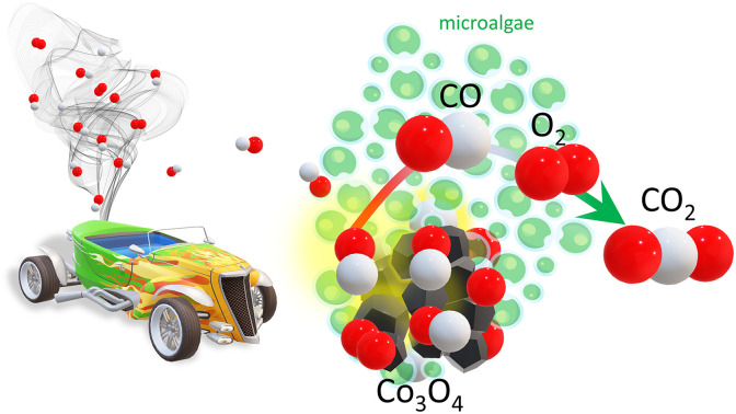
1. Introduction
Carbon monoxide is a by-product of incomplete fossil fuel combustion that can give rise to serious health issues such as hypoxia, in addition to environmental problems such as photochemical smog.1 Rapid urban development and industrialization led to a sharp rise in CO emissions generated by metallurgy, thermal power plants, petrochemical industries, coal mines, and other fields.2,3 In the transport sector, during the cold start of an engine, when the automotive three-way-catalyst does not yet function, mainly CO is discharged into the atmosphere.4 Hence, a huge number of studies focused on CO elimination, with catalytic CO oxidation to less toxic CO2 being the most effective and economical method. Furthermore, carbon monoxide oxidation in the recirculated flue gas of an internal combustion engine also increases the combustion efficiency, thus lowering the fossil fuel consumption.5,6 Apart from well-established noble metal catalysts, cobalt(ii,iii) oxide nanomaterials (Co3O4 NMs) have received considerable attention due to their abundance, low production costs, and excellent low-temperature catalytic performance.7–12
Despite progress and improvements in Co3O4 catalyst design, the synthesis methods are usually chemical or physical, while a biological approach has not yet been studied extensively. The typical synthesis routes often involve expensive and hazardous chemicals and procedures that counterproductively may impose negative effects on the environment. As an alternative, more environmentally friendly procedures are gaining importance. Recently, pollen has been used as a bio-template in catalyst preparation, providing a porous structure to deposit Co3O4,13 but the effect of the extract on Co3O4 synthesis was not studied. Organisms possess a variety of metabolites that can be employed as reducing agents, also featuring economic and environmentally-friendly aspects.14,15 Among various organisms, microalgae are recently gaining more attention due to the quick production of nutrient-rich biomass, as their CO2 fixation rate during photosynthesis is higher than that of terrestrial plants.16 Al Jahdaly et al. demonstrated the potential of marine red algae extract (Grateloupia sparsa) for Co3O4 NMs preparation, which were then used as electrode for energy storage applications.17 Their remarkable performance and stability indicated the potential of algal extract to fabricate high-value Co3O4 NMs via a sustainable strategy. However, the Co3O4 NMs synthesized using biological extract have not yet been tested for CO oxidation.
As mentioned, current research typically focused on Co3O4 NMs synthesized via chemical or physical approaches, combined with characterization and catalytic activity testing.7–12,18–20 Several spectroscopic and theoretical studies aimed at identifying the CO oxidation reaction mechanism on Co3O4 NMs.8,21–27 While Pollard et al. suggested CO adsorption on Co2+, other (theoretical) studies suggested CO adsorption on Co3+ ions as active sites.21 The abundance of surface Co3+ ions was also made responsible for cryogenic (−77 °C) CO oxidation on Co3O4 nanorods, mainly exposing (110) planes.12 The morphology-dependent activity of Co3O4 NM surfaces was determined as (110) > (100) > (111) by a theoretical study.22 However, Teng et al. reported that plate-like Co3O4 with exposed (111) planes was more active than cubic- or rod-shaped Co3O4, which exhibited (100) and (110) planes, respectively.23 Recently, the involvement of other crystal planes was studied via synthesizing various other morphologies such as straw-like nanorods, flower-like nanosheets, or honeycomb- and raspberry-shaped nanoparticles.24,25 The results revealed a complex surface chemistry with the reactivity depending on the exposed morphologies, crystal sizes and crystal facets.
Another strategy to study the relationship between structure and activity is introducing heteroatoms to induce structural defects. Lou et al. reported that doping by heteroatoms with larger ionic radii changed the lattice parameter and promoted reducibility as well as oxygen mobility.27 The doping effect was investigated for potassium, phosphorous, chlorine, and alkali metals (Na, K, and Li),28–31 revealing structural defects with either enhanced or inhibited activity. However, the combined effect of multiple elements has not been studied so far.
In the study presented herein, methanolic extracts of three different microalgae were used to synthesize Co3O4 NMs: Spirulina platensis (blue-green algae), Chlorella vulgaris (green algae), and Haematococcus pluvialis (green algae). These species are well-known and commonly cultivated for various purposes, including nutritional supplements, food additives, and bioactive compound production. To the best of our knowledge, this is the first work dealing with Co3O4 NMs synthesized from extracts of C. vulgaris and H. pluvialis. The involvement of metabolites was examined by ultraviolet-visible (UV-Vis) and attenuated total reflection Fourier transform infrared spectroscopy (ATR-FTIR), applied to the extract used for the synthesis, as well as after synthesis. The obtained Co3O4 NMs were characterized by X-ray diffraction (XRD), Brunauer–Emmett–Teller (BET), UV-Vis, scanning electron microscopy (SEM), transmission electron microscopy (TEM), electron energy loss spectroscopy (EELS), X-ray photoelectron spectroscopy (XPS), and universal ATR-FTIR (UATR). The availability of oxygen species was evaluated by temperature programmed desorption O2-TPD and reduction (H2-TPR). The catalysts were then tested for CO oxidation to establish a connection between structure, composition and activity. The catalytic performance was determined in a continuous-flow reactor at room temperature (RT), and the mechanism was studied by in situ diffuse reflectance infrared Fourier transform spectroscopy (DRIFTS) and differential scanning calorimetry (DSC). Altogether, the results illustrate the potential of algae extract components for Co3O4 NM synthesis as catalyst for CO oxidation, providing the basis for further studies.
2. Experimental
2.1. Extract preparation
S. platensis (courtesy of TOLO Green, Arborea, Italy) and C. vulgaris (CCALA 902) cultures were cultivated in Modified Zarrouk Medium and Bold Basal Medium (BBM), respectively, at 25 °C under stirring (250 RPM IKA® RH Digital Magnetic Stirrer) and 30 μmol m−2 s−1 photosynthetic photon flux density (PPFD) in 12/12 light cycle. H. pluvialis (CCALA 840) culture was grown in Modified Optimal Haematococcus Medium (OHM) at 31 °C with stirring (Zetalab®, Italy) and 50 μmol m−2 s−1 PPFD in 12/12 light cycle. The culture was supplied with 10 mM CH3COONa twice a week to improve growth and then daily for two weeks to increase the astaxanthin content. Modified Zarrouk medium was prepared according to the composition in Table S1† with pH adjustment to 9.0, thereafter autoclaved, and, after solution cool down, K2SO4 and MgSO4 were added to the medium as axenic. Similarly, BBM and Modified OHM media were prepared as reported in Tables S2 and S3,† the pH set to 6.2 and 8.0 for BBM and Modified OHM media, respectively, and the media were autoclaved.
The cultures were cultivated until reaching optical density at 750 nm (OD750) around 0.6, 0.4, and 0.3 for S. platensis, C. vulgaris, and H. pluvialis, respectively. Then, the biomass was separated from the media by centrifugation at 4 °C (1500 RPM for S. platensis, 2000 RPM for C. vulgaris, and 1200 RPM for H. pluvialis) and dried at room temperature for 7 days. The samples were imaged with an optical microscope (Fig. S2†). The obtained biomass was weighted, yielding 9 g of S. platensis, 2.75 g of C. vulgaris, and 2.5 g of H. pluvialis used for extract preparation.
2.2. Catalyst preparation
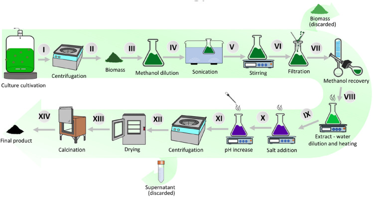
The microalgae-based Co3O4 NMs synthesis procedure is depicted in Fig. 1. First, the obtained algal biomass (Fig. 1I and II) was suspended in methanol (Merck® LiChrosolv® hypergrade) (Fig. 1III) according to the weight (540 ml for S. platensis, 165 ml for C. vulgaris, 150 ml for H. pluvialis). The flasks were sonicated for 30 min (Soltec® Sonica® 2400 ETH S3) (Fig. 1IV) and then stirred at 250 RPM (Fig. 1V) for 30 min. Next, the biomass was removed using standard filtration paper (Whatman®) (Fig. 1VI), and the solutions were evaporated using a rotary evaporator (Buchi Rotavapor™ R-210 Rotary Evaporator System) to remove about 70% of methanol (Fig. 1VII). Finally, the concentrated extracts were diluted using MiliQ H2O (Millipore®, Milan, Italy) to 1080 ml, 330 ml, and 300 ml for S. platensis, C. vulgaris, and H. pluvialis, respectively (Fig. 1VIII).
Fig. 1. Methodology of Co3O4 nanomaterial synthesis from microalgae.
The prepared extracts were heated to 85 °C under stirring at 250 RPM (IKA® RH Digital Magnetic Stirrer), with an extract sample taken and labeled as “extract before synthesis” (Fig. 1IX). In the next step, 13.52 g, 4.29 g, or 3.90 g of cobalt(ii) chloride hexahydrate (Carlo Erba®, Italy) was added to S. platensis, C. vulgaris, and H. pluvialis extract, respectively. After 15 min, the pH was raised to 8 (S. platensis and C. vulgaris) and 10 (H. pluvialis) using 1.25 M NaOH. After salt addition, the flasks were continuously heated and stirred for 1.5 h. Then, the solutions were removed from the heat source and left to cool down to RT. The obtained nanomaterials were separated from the supernatant by centrifugation at 4 °C with 4000 RPM (Heraeus® Megafuge® 1.0R) and dried at 80 °C for 24 h. The supernatant was labeled as “extract after synthesis” (Fig. 1XII). Next, the products were calcined in air in a muffle furnace (Gelman Instrument®) for 3 h at 450, 650 or 800 °C. Finally, the nanomaterials were stored at RT in the dark.
The samples were labeled according to the species used for the synthesis (Spirulina platensis – SP, Chlorella vulgaris – CH, Haematococcus pluvialis – HA) and their calcination temperature. A commercially available Co3O4 NM (Sigma-Aldrich®, Italy) after 400 °C calcination8 was labeled as SA400.
2.3. Extract characterization
The microalgae samples were observed using a polarized light (PL) optical microscope (Leica DM 2000, Leica Microsystems, Heerburg, Switzerland) coupled to a Leica EC3 digital camera (Leica Microsystems). One drop of suspended microalgae was placed on a glass slide, and a glass coverslip was placed above it. Images were acquired using LeicaSuite LAS EZ software.
UV-Vis measurements were performed on a UV-1600PC spectrophotometer at RT. The extract samples before and after synthesis were measured in the 200–1000 nm wavelength range. The nanomaterials were suspended in deionized water (10 mg ml−1) and sonicated for 15 min, followed by measurement from 300 to 1000 nm. The direct bandgap energy was calculated from the Tauc relation (eqn (1)):
| (αhν)2 = (hν − Eg) | 1 |
where α is the molar extinction coefficient, h is Plank's constant, ν is the light frequency, and Eg is the band gap energy. The bandgap energy was calculated by linear fit extrapolation of a plot of (αhν)2vs. energy (hv).
For ATR-FTIR, an FT-IR spectrophotometer (Vertex-70, Bruker Optics®) was used, equipped with an ATR unit (ZnSe crystal) and a liquid N2-cooled mercury cadmium telluride (MCT) detector. The extract samples (before and after synthesis) were diluted in ethanol in a 1 : 4 ratio, and the flow rate was adjusted to 5 ml min−1. The spectra were recorded using OPUS 6.5 software by performing 128 scans from 4000 to 900 cm−1 in absorbance mode with 4 cm−1 resolution. The working principle of the set-up is presented in Fig. S1A.†
2.4. Catalyst characterization
Crystallographic parameters were examined by XRD (Philips XPERT-PRO) at angles of diffraction (2θ) between 15° and 90° using a Cu-Kα radiation source (wavelength λ = 1.5406 Å). The measurement was carried out at 40 kV operating voltage and 30 mA current. The results were analyzed by Rietveld refinement using HighScore Plus® (v5.1) connected with ICDD® database. The d-spacing (d) was calculated based on the following equation (eqn (2)):
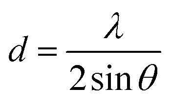 |
2 |
where λ is the wavelength of the incident X-ray beam (1.5406 Å), and θ is the angle of detector position from the incident X-ray beam. Based on the d-spacing values, the average lattice parameter (a) was calculated based on the following equation (eqn (3)):
 |
3 |
with h, k, and l corresponding to the Miller indices.
N2 adsorption–desorption isotherms were recorded at 77 K using an ASAP 2020 instrument (Micromeritics Inc., USA). Before each run, a known mass sample (ca. 0.18 g) was heated to 120 °C under vacuum for 2 h. Brunauer–Emmett–Teller (BET) and Barrett–Joyner–Halenda (BJH) models were used to calculate specific surface area and pore size/volume, respectively.
Prior to SEM, specimens were sputter-coated with an 8 nm layer of palladium and gold. The surface morphology was observed using a FEG-250, Quanta instrument applying an accelerating voltage of 5 kV. TEM was performed on a FEI TECNAI F20 field emission microscope equipped with a GATAN GIF Tridiem energy filter and a GATAN Rio16 CMOS camera. The micrographs were analyzed using ImageJ software (1.52a). Selected area electron diffraction (SAED) and EELS were employed to determine the structure and elemental composition in Co3O4 NMs, respectively.
XPS spectra were acquired at room temperature in a UHV chamber (base pressure <3 × 10⁻¹⁰ mbar) equipped with a Specs XR50© high-intensity non-monochromatic Al/Mg dual anode and a Phoibos 100© hemispherical electron energy analyzer with multichannel plate detector. All measurements were performed using the Al anode at 1486.6 eV, at normal emission geometry, and in fixed analyzer transmission with a pass energy of 20 eV. The spectra were calibrated to the C 1s peak at 284.8 eV and analyzed using CasaXPS.
For UATR-FTIR, measurements were done by another Fourier-transform infrared spectrometer (FTIR) (PerkinElmer Universal ATR, PerkinElmer, Waltham, MA, USA) coupled to Frontier Universal Diamond/ZnSe ATR crystal with a pressure arm. Each specimen was suitably pressed against the ATR crystal with the aid of the pressure arm to maintain proper contact between the sample and the ATR crystal. The FTIR spectrometer was operated in the 4000–400 cm−1 wavenumber range with 4 cm−1 resolution. Absorption intensity vs. wavenumber plots were digitally recorded by averaging 64 scans using Spectrum software (PerkinElmer Spectrum 10; PerkinElmer).
H2-Temperature Programmed Reduction (H2-TPR) experiments were performed in a continuous-flow fixed-bed quartz reactor under atmospheric pressure. For H2-TPR, 20 mg of the sample were placed between quartz plugs. After pre-treatment (20 vol% O2 in Ar, total flow: 50 ml min−1) at 400 °C for 30 min (heating rate 10 °C min−1) and cooling to 30 °C in 100 vol% Ar (total flow 50 ml min−1), each sample was heated from RT to 800 °C (heating rate of 5 °C min−1) in a mixture of 5 vol% H2 in Ar (total flow: 50 ml min−1). Hydrogen consumption was measured by a quadrupole mass spectrometer (QMS, Prisma Plus QMG 220, Pfeiffer Vacuum) with a MS signal of H2 (m/z = 2) detected online using Quadera software (v.4.40.019).
For O2-Temperature Programmed Desorption (O2-TPD), 50 mg of a sample was placed between quartz plugs in a continuous-flow reaction system and pre-treated (20 vol% O2 in N2, total flow: 50 ml min−1) at 400 °C for 30 min (heating rate 10 °C min−1), followed by cooling down to RT. Then, each sample was heated from RT to 500 °C under vacuum with a heating ramp rate of 10 °C min−1. The gas stream was analyzed by a quadruple mass spectrometer (Balzers Prisma QME 200), monitoring the MS signal of O2 (m/z = 32).
2.5. Catalytic CO oxidation
Differential scanning calorimetry (DSC) analysis during CO oxidation was performed on Netzsch STA 409 PC Luxx® in an alumina crucible. Before each cycle, samples (10 mg) were pre-treated in 20 vol% O2 in He (total flow: 50 ml min−1) at 400 °C for 30 min (heating rate 10 °C min−1). After cooling down to 25 °C under He, different vol% of CO and O2 were introduced under He flow (total flow 20 ml min−1) in 10 min intervals: at 10 min CO, 20 min CO + O2, 30 min O2, 40 min CO + O2, and 50 min CO. The scheme of the set-up is presented in Fig. S1B.†
CO oxidation was also conducted in a continuous-flow fixed-bed quartz reactor under atmospheric pressure. Typically, 20 mg of catalyst placed between quartz plugs was loaded into the reactor and pre-treated (20 vol% O2 in Ar, total flow: 50 ml min−1) at 400 °C for 30 min (heating rate 10 °C min−1). The catalyst bed temperature was controlled by a thermocouple. Subsequently, the sample was cooled to 30 °C, and a mixture of 5 vol% CO, 10 vol% O2, and 85 vol% Ar (total flow 50 ml min−1) was introduced. A quadrupole mass spectrometer (QMS, Prisma Plus QMG 220, Pfeiffer Vacuum) was used to monitor the effluent gas, and the MS signals of CO (m/z = 28), O2 (m/z = 32), CO2 (m/z = 44) and H2O (m/z = 18) were recorded online using Quadera software (v.4.40.019). The scheme of the set-up is presented in Fig. S1C.†
In situ diffuse reflectance infrared Fourier transform spectroscopy (DRIFTS) studies were carried out on a Bruker Vertex 70 spectrometer with a liquid N2-cooled MCT detector, a stainless-steel flow cell (Pike) features CaF2 windows and an oven. The inlet of the cell was connected to a gas manifold system with calibrated mass flow controllers to adjust the gas mixtures (pre-treatment: 20 vol% O2 in Ar, total flow: 50 ml min−1, reaction: 5 vol% CO, 10 vol% O2 in Ar, total flow: 50 ml min−1) and a quadrupole mass spectrometer (QMS, Prisma Plus QMG 220, Pfeiffer Vacuum). Each sample was pre-treated at 400 °C with a temperature ramp of 10 °C min−1 and kept at the maximum temperature for 30 min. Next, the sample was cooled to RT (100 vol% Ar), and the gases were switched to reaction conditions. The reaction temperature was increased by 5 °C min−1 and kept at the maximum temperature of 300 °C. The overall set-up is presented in Fig. S1B.† DRIFTS spectra were recorded with 4 cm−1 resolution using OPUS 6.5 software by averaging 128 scans to achieve a good signal-to-noise ratio. The DRIFTS set-up is presented in Fig. S1D.†
3. Results and discussion
3.1. Analysis of extracts
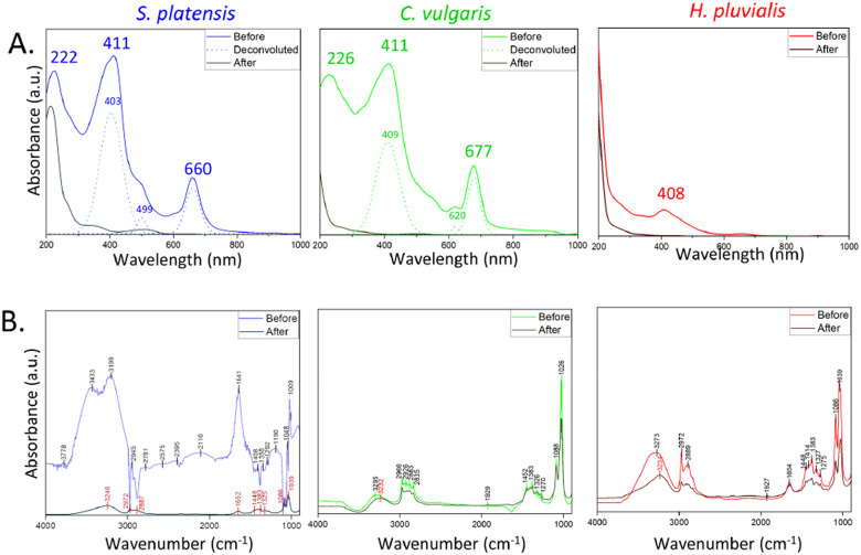
S. platensis, C. vulgaris, and H. pluvialis were investigated to determine differences in their morphology (see optical microscopy images in Fig. S2†) and metabolomic profile.32,33S. platensis is a well-known source of proteins with less abundant lipid and carbohydrate content. On the contrary, C. vulgaris has a decreased protein content and has been used mainly for its high lipid accumulation, while H. pluvialis is a source of astaxanthin belonging to carotenoids. Therefore, the effect of the metabolite composition on the synthesis process was evaluated by comparing the extract before and after synthesis by UV-Vis and ATR-FTIR (Fig. 2).
Fig. 2. Analysis of the extract before and after synthesis: (A) UV-Vis, (B) ATR-FTIR.
UV-Vis spectra of the extract before and after synthesis (Fig. 1IX and XII) are presented in Fig. 2A. Before synthesis, three major peaks were identified in the S. platensis extract: at 222 nm, 411 nm, and 660 nm. The first peak can be assigned to proteins owing to the presence of the carbonyl group in the peptide bond. The same peak was used to determine the presence and isolate various peptides from S. platensis by Lu et al.34 The peaks at 411 nm and 660 nm can be attributed to abundant compounds in the extract, such as carotenoids, chlorophylls, and phycocyanin with overlapping absorbance maxima.35 Similar values were observed for C. vulgaris extract before synthesis, with peaks at 226 nm, 411 nm, and 677 nm, the redshift probably due to structural differences between molecules belonging to the same group of metabolites.36 The H. pluvialis extract before synthesis exhibited one major peak at 408 nm characteristic of astaxanthin, usually observed at 450–500 nm. However, the absorbance peak shifted towards 400 nm after water dilution.37 After synthesis, all extracts show decreased absorbance, suggesting that the molecules derived from microalgae were indeed involved and employed in the synthesis of Co3O4 NMs.
The presence of functional groups in the extract before and after synthesis was further investigated by ATR-FTIR. The S. platensis extract exhibited a variety of identified functional groups belonging to proteins, lipids, and carbohydrates (Fig. 2B and Table S5†). Comparably, C. vulgaris and H. pluvialis extracts showed a lower peak intensity for functional groups of proteins and increased intensity of carbonyl groups belonging to carbohydrates (Fig. 2B, Tables S6 and S7†). After synthesis, S. platensis extract showed an intensity decrease in all previously identified peaks with visible redshift. In cases of C. vulgaris and H. pluvialis, the decrease was less significant, and a redshift was observed around 3000 cm−1, attributed to the NH group of proteins. In addition, potassium and phosphorous contents were analysed and the values are presented in Table S4.† Altogether, the results confirm a significant involvement of metabolites from the extract, mainly proteins and carbohydrates, in the Co3O4 NMs synthesis.
Recent studies indicated the potential of extracts to synthesize highly active Co3O4 NMs. Poonguzhali et al. utilized a fresh lemon juice-assisted auto-combustion method to synthesize Co3O4 NMs as gas sensors.38 The response was measured as a change in resistance due to chemical reactivity between the produced oxygen ions and tested gases such as H2, CO2, LPG, and (CH3)2CO. The material exhibited a short recovery–response time showing promising gas sensor applications. In a separate study, Khalid et al., tested Co3O4 NMs prepared from green chili or sunflower seed extracts and compared them with NM synthesized without extract.39 The utilization of sunflower seed extract resulted in the synthesis of Co3O4 NMs with the best photocatalytic and capacitive behaviour among the prepared materials. Although both studies proved the high catalytic activity of Co3O4 NMs, the extracts used for the synthesis were not analyzed, and therefore the role of the metabolites remained unclear. Herein, the utilization of microalgal metabolites was evaluated to provide insights into the synthesis mechanism. In the next steps, the obtained catalysts were characterized to establish a connection between synthesis, properties, and catalytic activity.
3.2. Characterization of Co3O4 NMs
The crystal structure of algae-derived cobalt oxide catalysts and the commercial reference were characterized by XRD (Fig. 3). All samples showed a diffraction pattern characteristic of Fd3̄m cubic spinel Co3O4 (JCPDS 01-078-5622) with (111), (220), (311), (400), (511), and (440) reflections (Fig. 3A). Co3O4 NMs synthesized from C. vulgaris and H. pluvialis extract exhibited additional peaks next to (220) and (400), indicative of NaCl (JCPDS 01-079-9877) formed probably due to the use of NaOH and CoCl2·6H2O during synthesis.
Fig. 3. XRD analysis of Co3O4 NMs: (A) wide angle, (B) selected magnified regions.
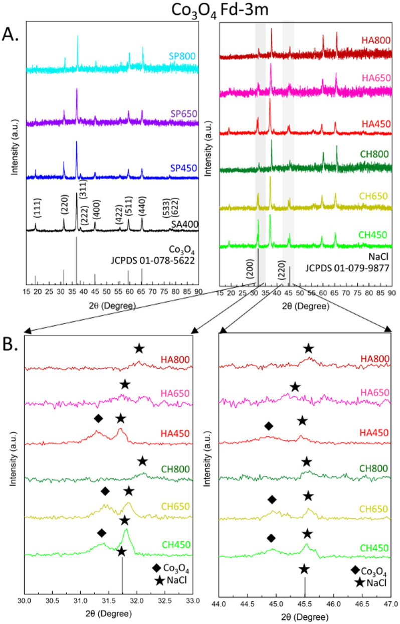
Another factor that caused changes in the pattern was the calcination temperature which, consistent with literature, shifted all peak positions to higher values due to lattice contraction40 (Tables S8–S11†), indicating a more strained crystal lattice. A small decrease was observed for S. platensis and C. vulgaris between 450 to 650 °C, while a more prominent decrease occurred for other Co3O4 NMs (Table 1 and Fig. S4B†). A similar tendency was observed for Co3O4 NMs synthesized via a chemical method and calcined at 400, 600, and 800 °C.41 The applied thermal energy contributed to a more ordered ion arrangement, decreasing the unit cell size (lattice contraction).
Structural properties of the different Co3O4 NMs.
| Sample | Crystallite size (nm) | Lattice parameter a = b = c (Å) | BJH adsorption cumulative pores volume (cm3 g−1) | BJH average pore width (nm) | BET surface area (m2 g−1) |
|---|---|---|---|---|---|
| SA400 | 21.9 | 8.067 | 0.266 | 26.8 | 43.7 |
| SP450 | 26.1 | 8.068 | 0.029 | 16.1 | 6.9 |
| SP650 | 24.1 | 8.057 | 0.024 | 18.5 | 6.1 |
| SP800 | 28.6 | 7.980 | 0.012 | 38.1 | 3.4 |
| CH450 | 16.4 | 8.058 | 0.068 | 25.6 | 13.3 |
| CH650 | 24.0 | 8.054 | 0.074 | 37.3 | 11.3 |
| CH800 | 40.3 | 7.951 | 0.019 | 28.6 | 4.6 |
| HA450 | 18.4 | 8.078 | 0.171 | 24.4 | 29.2 |
| HA650 | 23.1 | 8.014 | 0.141 | 39.2 | 19.5 |
| HA800 | 42.2 | 7.958 | 0.015 | 14.7 | 5.0 |
Structural changes were observed for HA650, for which (111) was absent, as well as CH800 and HA800, for which (111), (220), and (400) were not present (Fig. 3B). In addition, crystallite sizes increased upon calcination, indicating sintering of Co3O4 NMs: slight changes for Co3O4 NMs from S. platensis, but more pronounced growth for Co3O4 NMs from C. vulgaris and H. pluvialis (Table 1 and Fig. S4A†).
N2 physisorption isotherms were acquired to determine the textural properties of Co3O4 NMs. According to the IUPAC classification, the adsorption–desorption isotherms belong to type IV isotherms with an H1 hysteresis loop suggesting the presence of meso- and macro-pores (Fig. S5†).42 The pore distribution graphs, also shown in Fig. S6,† reveal a narrow spread of 2.5–4 nm width for all samples. In addition, SA400 Co3O4 NMs show a bell-shaped pore distribution around 5–80 nm. The high porosity correlates with a large surface area of SA400 Co3O4 NMs (43.7 m2 g−1) and huge pores volume (Table 1). However, even though SA400 Co3O4 NMs, CH450 Co3O4 NMs, and HA450 Co3O4 NMs show similar average pore width, their pore volume varies, suggesting pore blocking in the catalysts synthesized using microalgae. The porosity change with increasing temperature has been reported before.43 The calcination temperature was found to increase Co atom migration that leads to bigger Co3O4 crystallites which, in turn, causes structural strain in the material. This results in a shrinkage of the formed porous structures which finally collapse into quasi-spherical particles. Moreover, the gases formed during organic residue decomposition can further destroy structural integrity, or they may lead to carbon deposition decreasing the catalytic activity. These findings have been confirmed in the current study. Increasing the calcination temperature decreased porosity, pore volume, and surface area, with the most significant surface area decrease for Co3O4 NMs obtained from H. pluvialis extract (from 29.2 to 5 m2 g−1). A similar effect was observed for Co3O4 NMs synthesized using a metal–organic framework, with the surface area decreasing from 120.9 m2 g−1 to 22.6 m2 g−1 upon calcination temperature increase from 300 to 400 °C, likely due to sintering.43 The effect of calcination temperature on the surface area is presented in Fig. S4C.†
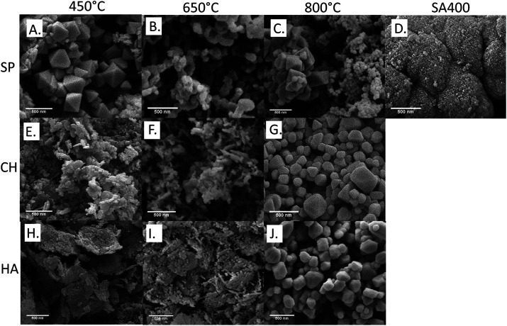
The morphologies of the synthesized and commercial Co3O4 NMs were examined by SEM. As presented in Fig. 4, SA400 Co3O4 NMs were spherical or quasi-spherical agglomerates with high porosity confirming the BET findings. Octahedral shape was observed for SP450 Co3O4 NMs with more abundant hollow spherical agglomerates upon increasing calcination temperature. Nanosheet morphologies were observed for CH450 and HA450 Co3O4 NMs with similar tendency regarding spherical form upon rising calcination temperature, as described previously.43 High resolution TEM images showed lattice fringes corresponding to (111) crystalline planes (Fig. S6A, C, E and G†). The obtained SAED patterns (Fig. S6B, D, F and H†) of the materials showed characteristic diffraction rings, which can be attributed to (111), (220), (311), (400), (511), and (440), in line with the XRD findings.
Fig. 4. SEM analysis of Co3O4 NMs: (A) SP450, (B) SP650, (C) SP800, (D) SA400, (E) CH450, (F) CH650, (G) CH800, (H) HA450, (I) HA650, (J) HA800.
The local valence state of Co3O4 NMs was studied in the TEM using the EELS technique (Fig. S7†). The O K-edge displays peaks a, b, and c in the 533–553 eV range. Peak a, referred to as the pre-edge peak, is ascribed to O 2p unoccupied states hybridization with the Co 3d orbital, while peaks b and c originate from O 2p state hybridization with the Co 4sp band.44 The increased pre-edge peak intensity compared with peak b is considered as a fingerprint of Co3O4 due to the high number of unoccupied Co 3d states.45 Moreover, the decreased electron counts of peaks a and b are correlated with oxygen vacancies in Co3O4 NMs,46,47 with rich oxygen vacancy indicated for SA400 Co3O4 NMs, followed by CH450, HA450, and SP450 Co3O4 NMs. The EELS spectra also display Co L3 and L2 edges at 780–800 eV, stemming from 2p3/2 and 2p1/2 core–shell electron transition into 3d orbitals in a pattern typical for Co3O4.44
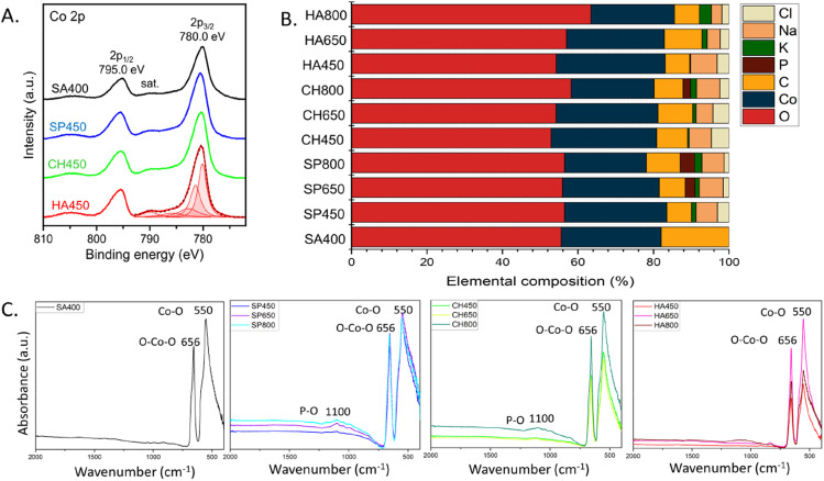
The catalyst surface composition was also examined by XPS, which provided evidence of the Co3O4 phase (Fig. 5A), confirming XRD and EELS. The region exhibits a doublet at 280.0 and 295 eV of Co 2p3/2 and Co 2p1/2 respectively, as well as satellite structures. While the binding energy of oxidized Co species are near identical, the peak shape clearly indicates Co3O4.48,49 Further, the Co 2p3/2 envelope matches the data perfectly, when fitted according to procedures for Co3O4 (using constraints for peak areas and positions), as shown for HA450. The same holds true for the analogous peaks of SP450, CH450 and SA400.
Fig. 5. Surface composition of Co3O4 NMs: (A) XPS Co 2p spectra, (B) elemental composition based on XPS analysis, (C) UATR-FTIR spectra.
The relative surface composition, derived from XPS, is displayed in Fig. 5B. The samples have similar oxygen content with a slight increase upon rising calcination temperature. The Co3O4 NMs synthesized using microalgae extract also showed the presence of sodium (from NaOH) and chlorine (from cobalt salt) added during the synthesis process, as also observed by XRD. In addition, Co3O4 NMs synthesized using microalgal extract contained potassium, whose percentage increased with calcination temperature, and phosphorus that was observed only in SP650, SP800, and CH800 Co3O4 NMs. Both potassium and phosphorus originated from the microalgae extract (Table S4†), which once more demonstrates the involvement of metabolites during synthesis. The variable potassium, phosphorus, carbon, and oxygen contents suggest surface segregation, which may also cause the differences in the Co3O4 NMs crystallographic parameters (Table 1).
The XPS results were confirmed by UATR-FTIR analysis of Co3O4 NMs, which also revealed the presence of phosphorous via a phosphorous–oxygen stretching vibration at 1100 cm−1 (ref. 50) in SP650, SP800, and CH800 Co3O4 NMs (Fig. 5C). All UATR-FTIR spectra showed peaks at 550 cm−1 belonging to Co–O stretching and 656 cm−1 corresponding to O–Co–O bridging vibration due to Co–O linkage.51 Moreover, no organic ligands were detected on the surface (Fig. S8†).
3.3. Oxygen availability of Co3O4 NMs
The address the reducibility/stability of the cobalt catalysts, H2-TPR was carried out, as presented in Fig. S9.† Typically, Co3O4 NMs exhibit two peaks corresponding to reduction of Co3+ to Co2+ and Co2+ to Co0, which may partly overlap. A lower temperature of H2 consumption indicates weaker Co–O bond strength, which should lead to better accessible oxygen species and thus higher oxidation activity.52
The lowest TPR temperatures of both peaks were observed for SA400 Co3O4 NMs, followed by HA450, CH450, and SP450 Co3O4 NMs. The lower temperature for HA450 than CH450 Co3O4 NMs shows the potential for oxidation performance, which could be hindered by other factors, such as the presence of sodium and chlorine. Increasing the calcination temperature shifted the peaks to higher TPR temperature, which should be a descriptor of lower activity. For HA650 and HA800 Co3O4 NMs, only one TPR peak was observed anymore, likely due to calcination-induced changes in the structure. The reducibility/stability of the cobalt catalysts was examined by H2-TPR, as presented in Fig. S9.† The detected peaks are also presented in Table S12.†
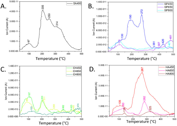
The availability of oxygen species was directly investigated by O2-TPD, i.e. the desorption of different oxygen species from the catalysts' surface (Fig. 6). Three types of oxygen species were detected in the spectra and, according to the literature,53 they can be assigned depending on their temperature range: physisorbed molecular and/or chemisorbed dissociated surface oxygen species desorbing at 50–150 °C, surface lattice oxygen desorbing at 150–450 °C rather easily forming oxygen vacancies, and bulk oxygen desorbing at 450–500 °C.53 The most intense signal was observed for SA400 Co3O4 NMs, mostly as surface lattice oxygen, in line with efficient oxidation performance following the Mars–van-Krevelen (MvK) mechanism. Abundant surface-active oxygens were also observed for HA450 and SP450 Co3O4 NMs. On the contrary, CH450 Co3O4 NMs showed an increased amount of molecular oxygen, which should lead to better catalytic performance than the other Co3O4 NMs synthesized from microalgal extract. Moreover, increasing the calcination temperature decreased the amount of desorbing oxygen, thus decreasing the Co3O4 NMs CO oxidation ability.
Fig. 6. O2-TPD of Co3O4 NMs: (A) SP400, (B) SP450, SP650, SP800, (C) CH450, CH650, CH800, (D) HA450, HA6550, HA800.
3.4. CO oxidation on Co3O4 NMs
To evaluate CO oxidation on the Co3O4 NMs, in situ DSC was applied (Fig. 7). Upon CO exposure, several processes can take place including adsorption, carbonate and CO2 formation.8,54 Both CO adsorption and oxidation are exothermic and can occur in parallel. The energy released was calculated based on the measured peak areas, as presented in Table S13.† For CO exposure, the strongest exothermicity with −14.4 J g−1 was observed for SA400 Co3O4 NMs, with significantly reduced values of −0.4, −2.4, and −6.5 J g−1 for SP450, CH450, and HA450 Co3O4 NMs, respectively. For CO2 formation, CO interacts with active Co sites and neighboring oxygen. The generated oxygen vacancy can be replenished by gas phase oxygen, but CO adsorption may also lead to dissociation and carbon deposition (which may be re-oxidized upon oxygen exposure). The strongest exothermicity for SA400 Co3O4 NMs is connected with its high activity, whereas the differences to other samples might originate from the formation of different carbonate species on the surface.
Fig. 7. In situ DSC analysis of Co3O4 NMs: SA400, SP450, CH450, and HA450.
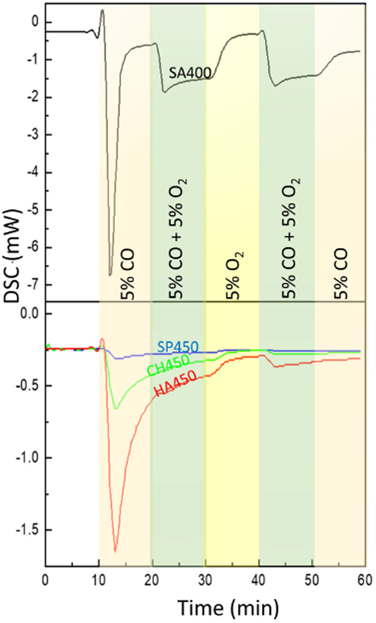
Co-dosing molecular oxygen then led to much smaller heat release (Fig. 7). This difference may be due to active oxygen species that were only present after pretreatment in oxygen.8 Even after a 10 min treatment with (pure) oxygen, the heat release remained reduced, i.e. the surface oxygen species were not replenished. A decrease in exothermicity was also observed for SA400 Co3O4 NMs in a following experiment with different gas composition (Fig. S10 and Table S14†). The results suggest a complex network of different interactions due to CO and O2 interacting with different sites, as discussed previously.8,26
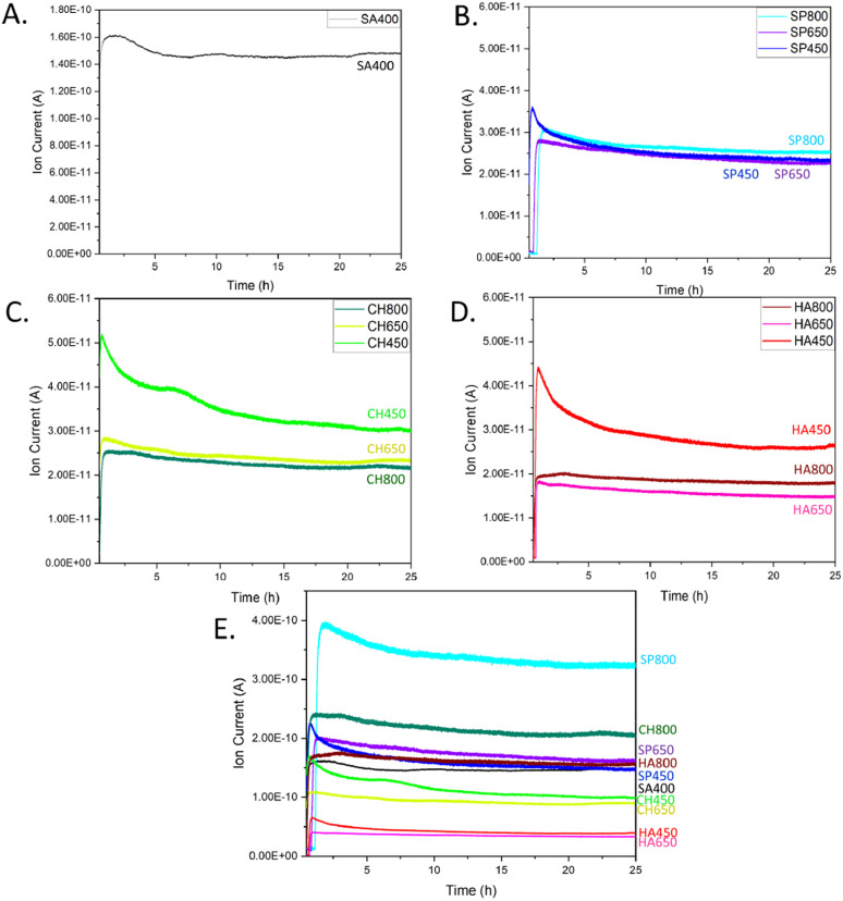
The various catalysts were then tested for CO oxidation in an atmospheric flow reactor, with results shown in Fig. 8. The CO oxidation activity of algae-derived Co3O4 NMs extract is described here for the first time along with a comparison to commercial Co3O4. The most intense CO2 signal, corresponding to the highest catalytic activity, was observed for SA400 Co3O4 NMs, followed by CH450, HA450, and SP450 Co3O4 NMs. This order correlates well with the one of oxygen vacancy content revealed by EELS. Among the tested microalgae, after calcination at 800 °C, Co3O4 NMs synthesized using S. platensis extract were the most active (SP800, Fig. S11†). For calcination at lower temperature, the highest activity was observed for the Co3O4 NMs synthesized using C. vulgaris extract (CH450, CH650).
Fig. 8. CO oxidation at room temperature over Co3O4 NMs: MS spectra of CO2 for (A) SA400, (B) SP, (C) CH, (D) HA. (E) CO2 signal normalized per surface area of SA400.
Increasing the calcination temperature rather decreased the catalytic activity of Co3O4 NMs synthesized from microalgae, which may be related to a decrease in surface area (Table 1). However, it increased the signal stability, with an activity decrease of only 11–19% for Co3O4 NMs calcined at 800 °C and 35–41% for Co3O4 NMs calcined at 450 °C (Fig. S12†).
For better and direct comparison, the catalytic activity was also normalized by the corresponding catalyst surface area, including SA400 as reference (Fig. 8E), revealing higher (normalized) catalytic activity of SP800, CH800, and SP650 Co3O4 NMs, which contained phosphorous, as indicated by XPS. The effect of phosphorus has been studied before, mainly as a dopant in Co3O4 NMs. During peroxymonosulfate (PMS) activation, due to the presence of phosphorus, more active cobalt sites were exposed, thereby exhibiting higher affinity and easier electron transfer for PMS, while weakening the O–O bond for the rapid generation of oxygen radicals.55
On the oxide catalysts of the current study, CO oxidation mainly follows a Mars–van-Krevelen (MvK) mechanism which involves reactant adsorption, lattice oxygen activation, reaction with active lattice oxygen, and CO2 desorption, paralleled by replenishment of oxygen vacancies by gas-phase oxygen.8,56 Although reaction of CO and chemisorbed oxygen cannot be fully excluded (Langmuir–Hinshelwood mechanism),26 an increased oxygen mobility induced by phosphorous should improve the catalytic activity. The promoting effect of phosphorous persists despite the presence of sodium and chlorine, which were reported to reduce oxygen mobility, thus rather poisoning catalytic oxidation.30,31 However, a lower sodium and chlorine content in HA650 Co3O4 NMs than in HA450 Co3O4 NMs did not increase the activity of the first. Nevertheless, HA800 Co3O4 NMs showed much better performance, probably due to higher potassium content. Potassium in the Co3O4 NMs lattice was assigned to promote oxygen activation by facilitating CO2 desorption, resulting in a more facile CO oxidation process.28 Accelerated charge transfer was also observed for Co3O4 anchored on nitrogen-doped carbon nanotubes, upon oxygen vacancies mobility in Co3O4, inducing active species Co–O–P.52 Moreover, the resulting lattice dislocations were examined for their enhanced adsorption and promoting polysulfide conversion activity.29 So far, the effects of phosphorous, potassium, chlorine, and sodium have been described, but only when the elements were introduced separately to Co3O4 NMs, whereas their simultaneous effect on CO oxidation had not been tested.
The catalytic activity was also correlated with the bandgap energy (Fig. S13 and Table S15†), representing the minimum energy required to excite an electron from the valence band to the conduction band. The lowest values were noted for SP800, CH800, and SP650 Co3O4 NMs, following the order of activity as depicted in Fig. 8E. The values belong to the charge transfer range between heterovalent cobalt ions, which may explain their electron mobility and lattice oxygen activity.57
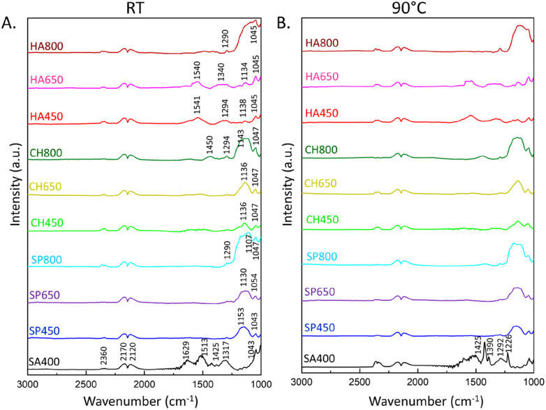
The catalytic reaction was also monitored by in situ DRIFTS, detecting species absorbed on the catalysts (Fig. 9, S14 and S15†). During CO oxidation, the IR spectra revealed gas phase bands of the product CO2 at 2360 cm−1, as well as peaks of gas phase CO at 2170 and 2120 cm−1.58 The peaks in the 1000–1700 cm−1 region correspond to various vibrations of adsorbed carbonates, likely just acting as spectators.26,59 The SA400 Co3O4 NMs showed formation of bridging carbonates at 1629 cm−1, bidentate at 1513 cm−1, and monodentate at 1425, 1317, and 1043 cm−1, while Co3O4 NMs synthesized using microalgae extract showed mostly monodentate (1541, 1540, 1450, 1340, 1294, 1290, 1051, 1054, 1050, 1047, 1045, 1043) and bridged carbonates (1153, 1143, 1138, 1136, 1134, 1130, 1111, 1107).26 The higher intensity of carbonate formation in SA400 Co3O4 NMs correlates with its higher CO2 production activity, while other Co3O4 NMs showed less pronounced performance with a tendency towards monodentate formation upon higher calcination temperature. This trend suggests a simpler binding geometry compared to bidentate or bridging carbonates, potentially resulting in lower structural complexity of carbonates on the catalyst surface. The carbonates were formed as soon as Co3O4 MNs were exposed to the reaction mixture, but their build-up was suppressed as the reaction progressed. Therefore, the formation of carbonates is likely limited by the adsorption sites on the catalyst surface. In addition, Co3O4 NMs synthesized using the same microalgae extract but subjected to different calcination temperatures show a variation in the detected IR spectra reflecting differences in the surface properties which could have an impact on the reaction pathway and the overall catalytic activity. Although the carbonates are not considered active participants during CO oxidation and usually act as spectators, they can behave as a physical barrier on the surface of the catalyst. The presence of surface carbonates may physically hinder the adsorption of CO or oxygen molecules onto the active sites of the catalyst, influencing the overall catalytic activity.8 Carbonates may cover or block active sites on the catalyst surface where CO or oxygen molecules would typically adsorb.
Fig. 9. In situ DRIFTS spectra of CO oxidation on Co3O4 NMs: (A) at room temperature (RT) after 25 minutes of the reaction, (B) at 90 °C after 13 minutes of the reaction.
The properties of the formed carbonates were further studied by thermal exposure. When the temperature was increased to 90 °C on SA400 Co3O4 NMs (Fig. 9B), the carbonate species decreased, whereas more gaseous CO2 was visible at 2360 cm−1. In the case of microalgae-derived Co3O4 NMs, the carbonate species rather remained adsorbed on the surface, suggesting higher thermal stability. A more stable carbonate intermediate suggests a catalyst that can endure prolonged exposure to high temperatures without undergoing significant structural changes, impacting both environmental and industrial applications.
Although the surface area of Co3O4 NMs obtained via a biological method was smaller than that of commercial Co3O4 NMs, their normalized catalytic activity showed the potential to improve CO oxidation due to microalgal components such as phosphorous or potassium. As a result, the environmentally harmful effect of CO emission to the atmosphere can be mitigated using sustainable catalyst preparation methods. In addition, insights gained from CO oxidation, which serves as a well-known benchmark reaction, may contribute to a better understanding of oxide-gas interactions and oxidative removal of other hazardous pollutants.
4. Conclusions
The present study exploited how extracts from three different microalgae can be employed for the synthesis of various Co3O4 NMs, further modified by different calcination temperatures, and using commercial spinel Co3O4 as reference. The focus was placed on the relationship between the structure, morphology, composition, reducibility, oxygen species and CO oxidation activity of the various Co3O4 NMs. The catalysts' structure/composition were characterized by XRD, SEM/TEM/EELS, XPS, their reducibility by H2-TPR, and oxygen availability by O2-TPD. Higher calcination temperature caused surface segregation of phosphorous and potassium, originating from the extract, which seems to promote the Co3O4 NMs in CO oxidation. Although commercial Co3O4 NMs exhibited the highest activity, when normalized to surface area, the activity of Co3O4 NMs derived from microalgae and calcined at high temperature was superior. The presence of phosphorous and potassium enhanced the catalytic activity, despite a previously reported poisoning effect of sodium and chlorine, which were also present as synthesis residues. During CO oxidation, in situ DSC and in situ DRIFTS revealed interactions between reactants and Co3O4 NMs, but also complexity related to pretreatment effects. The low surface area of Co3O4 NMs synthesized from microalgae is currently a limiting factor, which can be mitigated by future studies using modified synthesis techniques yielding higher surface area, creating highly active Co3O4 NMs based on biological extracts. Overall, the present study highlights the potential of microalgae to synthesize nanomaterials along environmentally-friendly routes, which can be used in automotive catalytic converters for reducing CO emissions, petrochemical refineries to comply with environmental regulations, and can play a key role in fuel cells by preventing carbon monoxide poisoning while ensuring efficient operation.
Author contributions
A. S.: investigation; methodology; data curation; software; formal analysis; validation; conceptualization; visualization; writing – original draft; writing – review & editing, N. Y.: investigation; methodology; data curation, T. W.: investigation; writing – review & editing, M. S. P.: resources; investigation, A. C.: investigation; methodology; writing – review & editing, R. O.: resources; writing – review & editing, G. C.: funding acquisition; resources; project administration; writing – review & editing, G. R.: supervision; conceptualization; methodology; resources; validation; project administration; writing – review & editing.
Conflicts of interest
There are no conflicts to declare.
Supplementary Material
Acknowledgments
AS was supported by an International PhD Program in Innovation Sciences and Technologies at the University of Cagliari, Italy, also funding a research stay at TU Wien. This research was funded in whole or in part by the Austrian Science Fund (FWF) [10.55776/F81] (SFB TACO, F81-P08). For open access purposes, the author has applied a CC BY public copyright license to any author-accepted manuscript version arising from this submission.
Electronic supplementary information (ESI) available. See DOI: https://doi.org/10.1039/d4ra00343h
References
- Westberg K. Cohen N. Wilson K. W. Science. 1971;171:1013–1015. doi: 10.1126/science.171.3975.1013. [DOI] [PubMed] [Google Scholar]
- Crippa M. Solazzo E. Guizzardi D. Van Dingenen R. Leip A. Nat. Food. 2022;(3):942–956. doi: 10.1038/s43016-022-00615-7. [DOI] [PubMed] [Google Scholar]
- Wang L. Liu Z. Yang H. Li H. Yu M. He T. Luo Z. Liu F. Fuel. 2021;306:121757. [Google Scholar]
- Yusuf A. A. Inambao F. L. Case Stud. Therm. Eng. 2019;14:100417. [Google Scholar]
- Shere A. Subramanian K. A. Int. J. Ambient Energy. 2022;43:8220–8238. [Google Scholar]
- Han L. Duan J. Qian D. Gong Y. Wang Y. Xie F. Su Y. Energies. 2022;15:438. [Google Scholar]
- Dien L. X. Chinh H. D. Nga N. K. Luque R. Osman S. M. Voskressensky L. G. Lam T. D. Ishida T. Murayama T. Mol. Catal. 2022;518:112053. [Google Scholar]
- Yigit N. Genest A. Terloev S. Rupprechter G. J. Phys. Condens. Matter. 2022;34:10. doi: 10.1088/1361-648X/ac718b. [DOI] [PubMed] [Google Scholar]
- Rupprechter G. Small. 2021;17:2004289. doi: 10.1002/smll.202004289. [DOI] [PMC free article] [PubMed] [Google Scholar]
- Falk T. Budiyanto E. Dreyer M. Büker J. Weidenthaler C. Behrens M. Tüysüz H. Muhler M. Peng B. ACS Appl. Nano Mater. 2022;5:17783–17794. [Google Scholar]
- Iablokov V. Barbosa R. Pollefeyt G. Van Driessche I. Chenakin S. Kruse N. ACS Catal. 2015;5:5714–5718. [Google Scholar]
- Xie X. Li Y. Liu Z. Q. Haruta M. Shen W. Nature. 2009;458:746–749. doi: 10.1038/nature07877. [DOI] [PubMed] [Google Scholar]
- Jiang B. Huang M. Cai D. Tan K. B. Zhan G. Catal. Commun. 2023;174:106597. [Google Scholar]
- Jamkhande P. G. Ghule N. W. Bamer A. H. Kalaskar M. G. J. Drug Deliv. Sci. Technol. 2019;53:101174. [Google Scholar]
- Maqbool Q. Yigit N. Stöger-Pollach M. Ruello M. L. Tittarelli F. Rupprechter G. Catal. Sci. Technol. 2023;13:624–636. doi: 10.1039/d2cy01395a. [DOI] [PMC free article] [PubMed] [Google Scholar]
- Jacob J. M. Ravindran R. Narayanan M. Samuel S. M. Pugazhendhi A. Kumar G. Curr. Opin. Environ. Sci. Health. 2020:100163. [Google Scholar]
- Al Jahdaly B. A. Abu-Rayyan A. Taher M. M. Shoueir K. ACS Omega. 2022;7:23673–23684. doi: 10.1021/acsomega.2c02305. [DOI] [PMC free article] [PubMed] [Google Scholar]
- Efremova A. Rajkumar T. Szamosvölgyi Á. Sápi A. Baán K. Szenti I. Gómez-Pérez J. Varga G. Kiss J. Halasi G. Kukovecz Á. Kónya Z. J. Phys. Chem. C. 2021;125:7130–7141. [Google Scholar]
- Feste P. D. Crisci M. Barbon F. Tajoli F. Salerno M. Drago F. Prato M. Gross S. Gatti T. Lamberti F. Appl. Sci. 2021;11:1–13. [Google Scholar]
- Popova M. Ristić A. Mavrodinova V. Maučec D. Mindizova L. Novak Tušar N. Catal. Lett. 2014;144:1096–1100. [Google Scholar]
- Pollard M. J. Weinstock B. A. Bitterwolf T. E. Griffiths P. R. Piers Newbery A. Paine J. B. J. Catal. 2008;254:218–225. [Google Scholar]
- Wang H. F. Kavanagh R. Guo Y. L. Guo Y. Lu G. Hu P. J. Catal. 2012;296:110–119. [Google Scholar]
- Teng Y. Kusano Y. Azuma M. Haruta M. Shimakawa Y. Catal. Sci. Technol. 2011;1:920–922. [Google Scholar]
- Wu R. C. Tang C. W. Chang M. B. Chang C. C. Wang C. C. Bin Wang C. Catal. Lett. 2020;150:3523–3532. [Google Scholar]
- Fuchigami T. Kimata R. Haneda M. Kakimoto K. I. Nanomater. 2018;8:662. doi: 10.3390/nano8090662. [DOI] [PMC free article] [PubMed] [Google Scholar]
- Lukashuk L. Yigit N. Rameshan R. Kolar E. Teschner D. Hävecker M. Knop-Gericke A. Schlögl R. Föttinger K. Rupprechter G. ACS Catal. 2018;8:8630–8641. doi: 10.1021/acscatal.8b01237. [DOI] [PMC free article] [PubMed] [Google Scholar]
- Lou Y. Wang L. Zhao Z. Zhang Y. Zhang Z. Lu G. Guo Y. Guo Y. Appl. Catal. B Environ. 2014;146:43–49. [Google Scholar]
- Wang L. Hu W. Shang Z. Cao X. Guo Y. Li J. Gu Q. Li K. Li X. Fuel. 2023;335:126968. [Google Scholar]
- Huang Y. Lv D. Zhang G. Cai Y. Li Q. Wang H. Ma Z. Energy Fuel. 2022;36:3339–3346. [Google Scholar]
- Li M. Bi F. Xu Y. Hao P. Xiang K. Zhang Y. Chen S. Guo J. Guo X. Ding W. ACS Catal. 2019;9:11676–11684. [Google Scholar]
- Tang W. Weng J. Lu X. Wen L. Suburamanian A. Nam C. Y. Gao P. X. Appl. Catal. B Environ. 2019;256:117859. [Google Scholar]
- Silva S. C. Ferreira I. C. F. R. Dias M. M. Filomena Barreiro M. Molecules. 2020;25:3406. doi: 10.3390/molecules25153406. [DOI] [PMC free article] [PubMed] [Google Scholar]
- Sandgruber F. Gielsdorf A. Baur A. C. Schenz B. Müller S. M. Schwerdtle T. Stangl G. I. Griehl C. Lorkowski S. Dawczynski C. Mar. Drugs. 2021;19:310. doi: 10.3390/md19060310. [DOI] [PMC free article] [PubMed] [Google Scholar]
- Lu J. Ren D. F. Xue Y. L. Sawano Y. Miyakawa T. Tanokura M. J. Agric. Food Chem. 2010;58:7166–7171. doi: 10.1021/jf100193f. [DOI] [PubMed] [Google Scholar]
- Marzorati S. Schievano A. Idà A. Verotta L. Green Chem. 2020;22:187–196. [Google Scholar]
- Sukhikh S. Prosekov A. Ivanova S. Maslennikov P. Andreeva A. Budenkova E. Kashirskikh E. Tcibulnikova A. Zemliakova E. Samusev I. Babich O. Life. 2022;12:1395. doi: 10.3390/life12091395. [DOI] [PMC free article] [PubMed] [Google Scholar]
- Tokarz D. Cisek R. El-Ansari O. Espie G. S. Fekl U. Barzda V. PLoS One. 2014;9:e107804. doi: 10.1371/journal.pone.0107804. [DOI] [PMC free article] [PubMed] [Google Scholar]
- Poonguzhali R. V. Kumar E. R. Srinivas C. Alshareef M. Aljohani M. M. Keshk A. A. El-Metwaly N. M. Arunadevi N. Sensor. Actuator. B Chem. 2023;377:133036. [Google Scholar]
- Khalid N. R. Gull A. Ali F. Tahir M. B. Iqbal T. Rafique M. Assiri M. A. Imran M. Alzaid M. Ceram. Int. 2022;48:32009–32021. [Google Scholar]
- Makhlouf S. A. Bakr Z. H. Aly K. I. Moustafa M. S. Superlattices Microstruct. 2013;64:107–117. [Google Scholar]
- Tharasan P. Somprasong M. Kenyota N. Kanjana N. Maiaugree W. Jareonboon W. Laokul P. J. Nanoparticle Res. 2022;24:1–14. [Google Scholar]
- Al-Ghouti M. A. Da’ana D. A. J. Hazard. Mater. 2020;393:122383. doi: 10.1016/j.jhazmat.2020.122383. [DOI] [PubMed] [Google Scholar]
- Lü Y. Zhan W. He Y. Wang Y. Kong X. Kuang Q. Xie Z. Zheng L. ACS Appl. Mater. Interfaces. 2014;6:4186–4195. doi: 10.1021/am405858v. [DOI] [PubMed] [Google Scholar]
- Zhao Y. Feltes T. E. Regalbuto J. R. Meyer R. J. Klie R. F. J. Appl. Phys. 2010;108:063704. [Google Scholar]
- Barreca D. Gasparotto A. Lebedev O. I. MacCato C. Pozza A. Tondello E. Turner S. Van Tendeloo G. CrystEngComm. 2010;12:2185–2197. [Google Scholar]
- Zhuang L. Jia Y. He T. Du A. Yan X. Ge L. Zhu Z. Yao X. Nano Res. 2018;11:3509–3518. [Google Scholar]
- Zhu H. Song X. Han X. Zhang X. Bao J. Zhang N. He G. Environ. Sci. Technol. 2020;54:8601–8611. doi: 10.1021/acs.est.0c03427. [DOI] [PubMed] [Google Scholar]
- Choya A. De Rivas B. Gutiérrez-Ortiz J. I. López-Fonseca R. Ind. Eng. Chem. Res. 2022;2022:17854–17865. doi: 10.1021/acs.iecr.2c03245. [DOI] [PMC free article] [PubMed] [Google Scholar]
- Lukashuk L. Yigit N. Li H. Bernardi J. Föttinger K. Rupprechter G. Catal. Today. 2019;336:139–147. [Google Scholar]
- Bekiaris G. Peltre C. Jensen L. S. Bruun S. Spectrochim. Acta, Part A. 2016;168:29–36. doi: 10.1016/j.saa.2016.05.049. [DOI] [PubMed] [Google Scholar]
- Ahmed I. Wageh S. Rehman W. Iqbal J. Mir S. Al-Ghamdi A. Khalid M. Numan A. Polymers. 2022;14:2685. doi: 10.3390/polym14132685. [DOI] [PMC free article] [PubMed] [Google Scholar]
- Feng B. Shi M. Liu J. Han X. Lan Z. Gu H. Wang X. Sun H. Zhang Q. Li H. Wang Y. Li H. J. Hazard. Mater. 2020;394:122540. doi: 10.1016/j.jhazmat.2020.122540. [DOI] [PubMed] [Google Scholar]
- Wang X. Li X. Mu J. Fan S. Chen X. Wang L. Yin Z. Tadé M. Liu S. ACS Appl. Mater. Interfaces. 2019;11:41988–41999. doi: 10.1021/acsami.9b08664. [DOI] [PubMed] [Google Scholar]
- Kersell H. Hooshmand Z. Yan G. Le D. Nguyen H. Eren B. Wu C. H. Waluyo I. Hunt A. Nemšák S. Somorjai G. Rahman T. S. Sautet P. Salmeron M. J. Am. Chem. Soc. 2020;142(18):8312–8322. doi: 10.1021/jacs.0c01139. [DOI] [PubMed] [Google Scholar]
- Gao Q. Li H. Wang X. Han B. Xia K. Wu J. Zhou C. Dong J. Appl. Surf. Sci. 2022;574:151632. [Google Scholar]
- Song L. Liu Y. Zhang S. Zhou C. Ma K. Yue H. Ind. Eng. Chem. Res. 2022;61:14783–14792. [Google Scholar]
- Qiao L. Xiao H. Y. Meyer H. M. Sun J. N. Rouleau C. M. Puretzky A. A. Geohegan D. B. Ivanov I. N. Yoon M. Weber W. J. Biegalski M. D. J. Mater. Chem. C. 2013;1:4628–4633. [Google Scholar]
- Zhang Q. Mo S. Li J. Sun Y. Zhang M. Chen P. Fu M. Wu J. Chen L. Ye D. Catal. Sci. Technol. 2019;9:4538–4551. [Google Scholar]
- Weilach C. Spiel C. Föttinger K. Rupprechter G. Carbonate formation on Al2O3 thin film model catalyst supports. Surf. Sci. 2011;605(15–16):1503–1509. [Google Scholar]
Associated Data
This section collects any data citations, data availability statements, or supplementary materials included in this article.


