Abstract
Natural surfaces excel in self-renewal and preventing bio-fouling, while synthetic materials placed in contact with complex fluids quickly foul [1, 3]. We present a novel biophysics inspired mechanism [4, 5] for surface renewal using actuating surface topography, generated by wrinkling. We calculate a critical surface curvature, given by an intrinsic characteristic length scale of the fouling layer that accounts for its effective flexural or bending stiffness and adhesion energy, beyond which surface renewal occurs. The effective bending stiffness includes the elasticity and thickness of the fouling patch, but also the boundary layer depth of the imposed wrinkled topography. The analytical scaling laws are validated using finite element simulations and physical experiments. Our data span over five orders of magnitude in critical curvatures and are well normalized by the analytically calculated scaling. Moreover, our numerics suggests an energy release mechanism whereby stored elastic energy in the fouling layer drives surface renewal. The strategy is broadly applicable to any surface with tunable topography and fouling layers with elastic response.
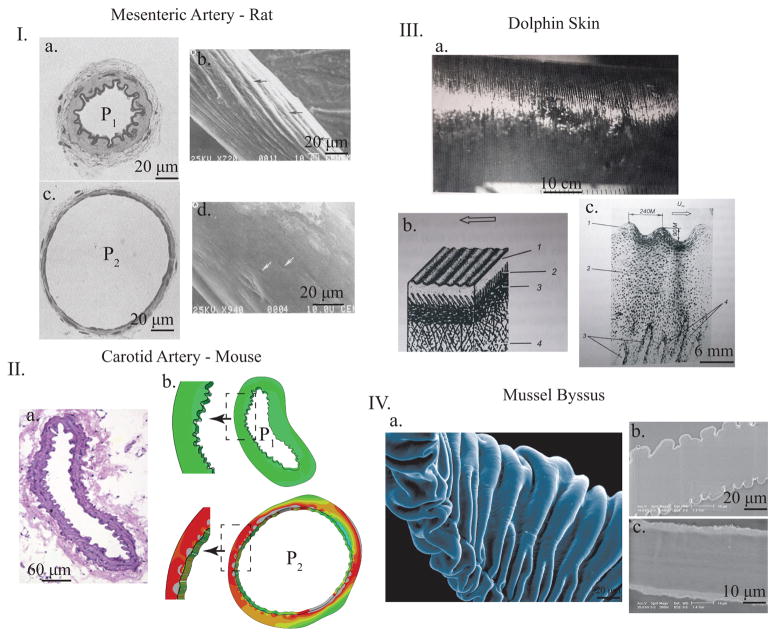
Natural surfaces, such as the inner lining of arteries, are far superior at resisting unwanted fouling as compared to artificial surfaces [1, 2]. For decades material scientists have attacked the problem of fouling through chemical surface modification to reduce interfacial energy, however these strategies are not sufficiently general to create a sustainably non-fouling surface [2, 3]. Nature solves the problem of surface self-renewal by using a multi-scale approach [1, 3]. Inherently ‘living’ and molecular aspects of natural surfaces include a biochemical powerhouse of specialized interfacial cells such as the endothelium lining of blood vessels or epithelial cells on skin and hollow viscus organs [3]. On a more macroscopic level, many natural surfaces are endowed with non-flat surface texture or topography [4, 5]. Wrinkling, a continuous and smooth surface amplitude undulation [6–9], is one of the most ubiquitous topographic patterns observed in nature: arteries [5, 10, 11] (see figure 1I. and II.), lung surfactant [8], ureter [12], skin (see figure 1III.) [4, 13, 14], mussel byssus (see figure 1IV.) [5], intestines [15], and the brain [16]. Many of these wrinkling interfaces are also under constant threat of biofouling such as platelet/thrombus adhesion in arteries [10] or bacteria in the lung/ureter/skin and on marine surfaces [17, 18]. Furthermore, these natural surface topographies often change or actuate as a function of driving forces in the environment, such as the wrinkling and un-wrinkling of arteries with pulse pressure (see figure 1I. and II.) [11].
FIG. 1.
Representative images of wrinkling surfaces in various biologic systems. I. Muscular artery from rat mesentery. a. and c. show the fixed histology at low (P1) and high (P2) blood pressures while b. and d. show SEM images of silicone casts of similar non-fixed arteries at equivalent pressures to the histology slides. In both sets of images, it is apparent that wrinkle and fold patterns appear on the inside of the artery at lower pressures and disappear as the artery distends with higher pressure (adapted with permission from [11]). II a. Histology of mouse carotid artery with luminal (inner) wrinkling. b. and c. show numerical simulations where this exact artery geometry is pressurized, showing the smoothing out of luminal wrinkles with increasing luminal pressure, showing the generality of the mechanism. III. Dolphin skin with periodic macroscopic wrinkles (a.) and the representative histology (b.) and (c.), adapted with permission from [13]. IV. Mussel byssus showing the intricate external wrinkles with SEM (a.) and the two states of the byssus under different conditions wrinkles (b.) and flat (c.), adapted from [5].
Such surface topography can greatly improve antifouling characteristics and functionality [1, 2, 18–26]. In this paper, building upon the rich literature of non-linear surface elastic instabilities [27–30], we explore a new mechanism of antifouling in which actuation from a smooth to a wrinkled surface induces topography-driven delamination of films adhered to the surface. The surface remains undamaged during the entire process and hence repeated actuation yields a “self-renewing” surface that can prevent continued build-up of foulant. A combination of theory, simulations, and experiments show that surface curvature κ (which quantifies the local topography) couples to surface renewal through a general relationship κc ~ 1/ℓec, where the intrinsic length scale ℓec, calculated explicitly, depends on interfacial adhesion energy and the effective elastic bending response of an adhered layer, and κc is the threshold curvature to detach the fouling layer.
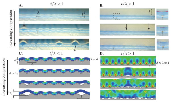
In general, a bilayer with a thin stiff membrane adhered to a thicker soft substrate under an applied strain ε wrinkles with two characteristic length scales, wavelength λ ~ h×(Em/Es)1/3 and amplitude , where Em is the membrane modulus, h is membrane thickness, and Es the substrate modulus [6, 7]. The second relationship is the well known inextensibility condition [4, 8, 31]. Suppose now that to the flat or weakly wrinkled bilayer is adhered a softer patch of material with a modulus Ep and thickness t representing a bacterial film or platelet aggregate forming the nidus of a blood clot on an arterial surface. The foulant patch being softer than the membrane layer (Em ≫ Es ≳ Ep) means that the patch does not influence the mechanics of wrinkling set by the substrate and membrane (see Supplementary Information: SI 1.1-Wrinkled Topography and videos 1–5). The interfacial stability is initially dominated by the chemical interaction between the surface and the patch, defined through the adhesion energy γ [27–30]. As the bilayer begins to wrinkle, the topography, characterized by surface curvature defined as κ = A/λ2, grows as amplitude increases with bilayer compression. At some critical amplitude Ac or, equivalently, critical curvature κc = Ac/λ2, the adhered patch begins to delaminate from the wrinkled surface forming discrete blisters of length l and amplitude Al that co-exist with still attached material (see figure 2). Moreover, once deadhesion nucleates, interfacial cracks spread beyond the initial failure zone inducing delamination of the entire patch (see SI videos 1–5). Since the wrinkling mechanics of the bilayer are preserved during this deadhesion process, one may stretch the surface back to its the original clean state, hence the term ‘a mechanically-renewing’ surface.
FIG. 2.
Representative images near A ~ Ac for thin-patch limit (A/C, t/λ = 0.25) and thick-patch limit (B/D t/λ = 1.25), for experimental soft silicone patches on wrinkling surfaces (top) and finite element simulations (bottom), see SI for details (SI 1.2-Silicone Patch Experiment, 1.3-FEA Simulation Methods, and 1.4-Elastic Energy Color Map). In the thin-patch limit, the patch conformally follows the wrinkling surface with strain energy distributed throughout its thickness. As Ac is approached, strain energy release through rotation off the surface into a less curved shape drives delamination (see SI videos 1 and 3). In the thick-patch limit, a boundary layer of increased strain energy exists near the wrinkled interface with a penetration length d ~ λ. As Ac is reached, the stored boundary layer energy is released driving patch detachment without much global rotation (see SI videos 2, 4, and 5). Inset in B shows zoom of patch/membrane interface: patch bottom (red line) and membrane top (blue line).
Using finite element analysis (FEA) and silicone patch experiments, we study the dependence of Ac on γ and the ratio of patch thickness to surface wavelength (t/λ), the dominant dimensionless parameter in the problem. Quasi-static simulations are performed using the ABAQUS dynamic explicit solver (Simulia, Dessault System, RI) (see SI 1.3-FEA Simulation Methods for simulation details). The patch (foulant), membrane, and substrate are modeled as hyperelastic materials under plainstrain conditions. Working within the general contact formulation of the explicit solver, a cohesive zone model (CZM) is used for the patch/membrane interface. The interfacial cohesive stress σcoh is related to the adhesion energy density , where δcoh is the interface thickness (initially δcoh = 0 with a stress free interface and interfacial failure occurs when δcoh = δcritical) and kc is the cohesive stiffness parameter [32]. Here we use γ×area as the interfacial adhesion energy between two materials. Physical experiments are carried out using silicone membranes, 250–3000 μm in thickness, adhered to initially flat bilayers, that upon compression wrinkle with a well defined wavelength λ = 1.5 mm (see figure 2A/B and SI 1.2-Silicone Patch Physical Experiments).
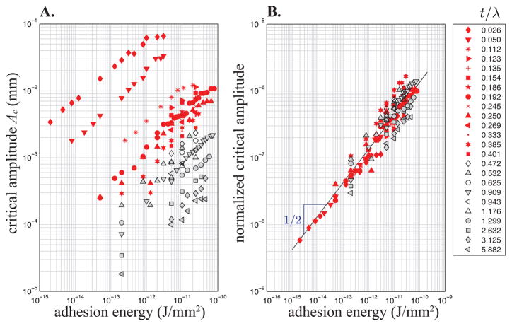
The measured critical amplitudes spread over five decades, with a general trend toward increasing critical amplitude with increasing adhesion energy, and decreasing critical amplitude with increasing ratio t/λ (see figure 3). Both trends are non-linear and follow a power law behavior. Moreover, the simulations and physical experiments show a strong cross-over behavior between ‘thin’ and ‘thick’ patches. For thin patches, those with t/λ < 1 (see figures 2A/C and red data in figure 3), the patch conformally follows the surface topography leading to build up of strain energy throughout the thickness of the patch. As patch thickness increases and becomes greater than the wrinkle wavelength, t/λ > 1 (see figures 2B/D and black data in figure 3), the strain energy is strongly concentrated in a near-interface boundary layer with the patch free surface remaining nearly undeformed and seemingly unaffected by the interfacial deformation field. In both cases, the simulations point toward an energy release mechanism whereby elastic energy stored in the patch drives interfacial crack propagation. As figure 2C/D and SI videos 3 and 4 show, interfacial failure is accompanied by a simultaneous decrease in local strain energy within the length of patch above the failed interface, l.
FIG. 3.
A. Log-log plot of Ac versus adhesion energy over a range of t/λ ratios, for Ep ≈ 30 kPa and νp ≈ 1/2 (Em ≈ 1.23 GPa, Es ≈ 15.8 MPa, νm ≈ νs ≈ 1/2). B. The over five decades of critical amplitudes are collapsed onto a master curve by normalization with the calculated theoretical scaling law (see Eq. 1). Here the solid line represents the relation where c ≈ 0.134 is obtained by fitting the thin patch data. In A and B open and gray symbols correspond to the thick limit t > λ/p with p ≈ 2.4.
In the theoretical analysis, we study the energetics of the patch and interface as the bilayer surface wrinkles. The effect of the wrinkling is imposed via a boundary condition along the interface (see SI 1.1-Wrinkled Topography). Assuming the deformation occurs quasi-statically, in the thin patch limit, bending energy dominates patch elasticity and is estimated as UB = (Bp/2) ∫S κ2 dS ~ (Bp/2)(A/λ2)2S, where S = bL, L is system length, b its width, and is patch bending stiffness. Here νp is the Poisson ratio of the adhered material. As part of the patch (length l < L) de-adheres, the elastic energy gains two new contributions: the new bending energy of the detached region with smaller curvature and the elastic energy dissipated during the transition: , where Sl = bl is the area of detached interface. Thus, the available elastic energy in the system is .
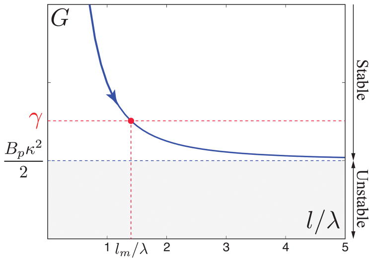
Since new surfaces are created during interfacial failure, the important function to study is the total energy UE +γSl. The possibility of having an equilibrium state requires the analysis of the condition ∂lUE +γb = 0 that can be studied by introducing the energy release rate G ≡ –∂lUE/b [33]. We obtain G ~ (Bpκ2/2)(1 + λ2/l2) a monotonically decreasing function of l (see figure 4). Note that the scaling analysis does not capture the exact form of the energy release function G for l/λ < 1, which must be bounded for small defects as it is observed in the simulations (see SI figure S3) [33].
FIG. 4.
Energy release rate as a function of the dimensionless fracture length l/λ. A patch with an initial detached length l increases its length to the equilibrium length lm if Bpκ2/2 < γ (or ). For Bpκ2/2 ≥ γ (or ), G is always larger than the interfacial adhesion energy (gray region) and then the fracture propagates without arrest.
There is interfacial fracture while G > γ until the detached region grows to reach the condition G = γ and the equilibrium length . Here ℓec = (Bp/γ)1/2 is an intrinsic length scale (see below), similar to an elastocapillary length, whose value depends on the particular physics dominating the elastic response of the adhered layer. Figure 4 shows that an equilibrium solution exists for Bpκ2/2 < γ (or ), but the system is unstable for any initial value of l if Bpκ2/2 ≥ γ (or ) when there is always available energy to produce fracture. Thus, the threshold condition for complete detachment corresponds to . It defines the critical amplitude for patch deadhesion as . In figure 3B, we plot the critical simulation amplitudes normalized by λ2/Bp 1/2; the red data points all collapse onto a single master curve given by c×γ1/2, in agreement with the theoretical scaling analysis.
In the thick limit t ≫ λ, the increased thickness of the patch prevents energy release by pure rotation or bending. The simulations and experiments point toward a near-interface mechanism whereby only the strains near the bound interface are released (see figure 2B/D and SI videos 4 and 5). The elastic strain energy of a thick free slab is U0 ~ Epε2tS/2 where ε is the strain imposed and tS is the volume. However, near the wrinkled interface, the local strain energy is increased because of the extra surface deformation field which is proportional to εp ~ ∂yux ~ A/λ. Similarly, the layer deformed by the wrinkled substrate has a volume d × S where d is a penetration length estimated as d ~ λ. Hence, the strain energy in the attached thick patch is . Since the patch is thick, once a subset of length l detaches, it initially lacks sufficient freedom to bend and release the compressive strain by rotating, therefore it keeps its initial strain energy U0. The new elastic energy is , where the last term gives the release of elastic energy because of fracture. We obtain for the energy release function and the critical amplitude in the thick patch limit: Ac ~ λ2/(Epλ3)1/2 × γ1/2.
The thin and thick scalings suggest that the critical amplitude can be written in general as , where c is the fit constant for the thin limit, is an effective bending stiffness, and d is a penetration length that accounts for the depth of the deformation in the patch. We expect d = t in the thin limit and d = λ/p in the thick limit where p is a free parameter. Because of continuity in the definition of the penetration length, d = t for t < λ/p and d = λ/p for t > λ/p, hence the parameter p captures the position of the crossover.
In figure 3B, we optimize the parameter p by using the least square method and obtain p ≈ 2.4 (see SI 1.5-Thin and Thick Limit Crossover Analysis). Thus, the criterion for topography driven deadhesion then becomes
| (1) |
A generalization of the definition for the elastocapillary length to ℓec = (Bd/γ)1/2 gives the condition κc ~ 1/ℓec for deadhesion. Interestingly, for a configuration with a prescribed wavelength, the maximum curvature is achieved for , or κ ~ 1/λ, showing that a given topography has the potential to detach patches with elastocapillary lengths larger or similar to λ.
Nature inspired topography induced surface renewal introduces a new mechanism for mechanically coupled interfacial failure adding to the existing literature dominated by edge and wrinkle delamination mechanisms [18–21, 27–30, 33]. To compare the different mechanisms, we re-write the given formulations in terms of critical strains for interfacial failure. For our topography mechanism, the critical nominal compressive strain εc at which delamination nucleates is related to the critical amplitude as , where we have included the numerical prefactors computed in [8, 31] and the strain ε0 that accounts for the initial strain that is necessary to start the wrinkling configuration. Equation 1 shows that the critical strain can be predicted to be
| (2) |
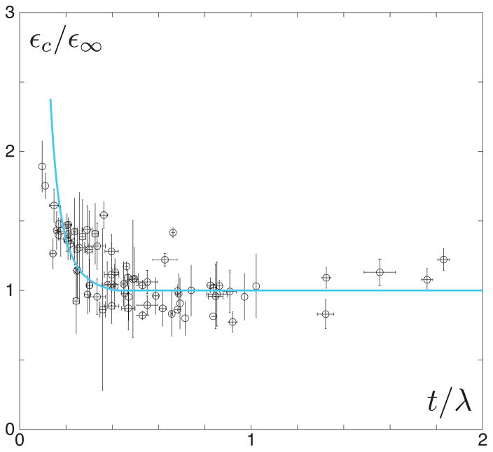
It is noteworthy that εc ~ t−3 in the thin limit t/λ ≪ 1 and in the thick limit t/λ ≫ 1. To check this relation, we carried out a set of experiments where patches with varying thicknesses were placed on top of a bilayer surface and measured the critical strain for deadhesion. Figure 5 compares the normalized critical strain obtained from experiments with the predicted values.
FIG. 5.
Pieces of soft silicone are placed onto initially flat bilayer surfaces. The support bilayer (Em ≈ 3MPa, Es ≈ 30 kPa, νm ≈ νs ≈ 1/2) is compressed and wrinkles appear (λ ≈ 1500μm) growing in amplitude as a function of nominal strain according to the inextensibility relation . Multiple patch thicknesses are tested from 250 to 2750 μm, giving a range of t/λ values both within the thin (see figure 2A) and thick (see figure 2B) regimes. The qualitative mechanism of deadhesion observed in these physical experiments is nearly identical to that seen with simulations (compare to experimental and numerical images in figure 2). Here we plot the cumulative critical strains for different experimental surfaces with identical wavelength. The open circles and error bars correspond to the average of three experiments done with each patch on an individual surface and the standard deviations, respectively. To control for variability in adhesion energy, which is sensitive to small changes in sample preparation, the critical strain for deadhesion εc is normalized in each data set by the smallest critical strain ε∞, which usually corresponds to the thickest patch. The solid curve represents εc/ε∞ predicted by Eq. 2, where Ep ≈ 30 kPa, γ ≈ 0.02 J/mm2, νp ≈ 1/2, and ε0 ≈ 0.1 for this particular system. The data clearly fall into two regimes: a thickness dependent and thickness independent regime. This is in agreement with our simulations and analytical predictions, whereby in the thin-patch limit εc ~ 1/t3 while in the thick-patch limit there is no dependence on t.
In general, for a topography with a given wavelength, the energy release rate is G ~ (Bd/2)κ2 ~ Bdε/λ2 in the large failed interface limit l → ∞. It increases as patch thickness becomes larger showing that thick patches are easier to detach than thin patches as seen in figure 3A. This is simple to understand, thin patches can easily follow the topography and the available energy is low. Thus, different mechanisms for delamination must be compared in the thin patch limit when patches are harder to detach. Conversely, for a given patch thickness, the energy release rate decays for small (G ~ λ) and large (G ~ 1/λ2) wavelengths, showing that G has a peak and delamination is optimized for an imposed wavelength λ ~ t.
A key feature of the proposed mechanism is to generate fracture propagation without arrest, therefore leading to the complete detachment of the patch. Other mechanisms [28, 33] for film delamination are comparable to our thin regime analysis and produce a similar effect. The basic element is to have a continuous supply of elastic energy for the fracture process that gives a constant value for the energy release rate in the limit of a large failed interface, l → ∞. This is the case for edge delamination [18, 21, 28, 33] where the elastic energy and energy release rate for a patch de-adhered a length l are UE ≈ Eptε2b(L – l)/2 and G = Eptε2/2 ~ ε2. However, G ~ Bpε/λ2 ~ ε in the proposed topographic mechanism (thin limit) showing that for small strains more energy is available for fracture in the form of wrinkles.
Another competing mechanism is when the adhered patch itself is sufficiently stiff to wrinkle without necessity of a given topography (there is no membrane)[27, 29, 30]. This possibility is constrained to patches with large mismatch Ep/Es ≫ 1, since the critical strain for wrinkling is [4, 6, 7, 9]. In the large mismatch limit the elastic energy of the system can be computed as where λw ≈ (Bp/Es)1/3 gives the classical relation for wrinkles [6, 7]. The corresponding energy release rate is , that is similar to the expression for an imposed topography in the thin patch limit because the available energy for fracture is stored in wrinkles in both cases. However, wavelength is imposed as a boundary condition for the topographic mechanism making it an independent control parameter while λw is an emergent length scale dictated by material properties.
Interfaces abound in nature and are often at risk for fouling. As figure 1 shows, many natural interfaces from inside of arteries to the skin of marine animals are wrinkled. These wrinkling patterns are not static and undergo dynamic changes in amplitude. No study to date has explored the potential role of such dynamic structures at complex interfaces. In this paper, we define a physical mechanism whereby dynamic wrinkling leads to surface renewal when the response of the adhered fouling layer is elastic. Many biological fouling layers (biofilms), including thrombus, show complex viscoelastic constitutive responses [3, 20, 22, 23, 25, 34]. Such materials are elastic on short time scales T < Λ, where Λ is an intrinsic elastic relaxation time of the given material, and have a more dissipative viscous response at T > Λ. Recent work [34] showed that Λ approaches a universal value of 1100 seconds for a wide variety of biologic biofilm like materials. From the perspective of our current mechanism of fouling layer disruption, this means that topographic surface renewal in biologic systems with biofilm-like fouling, including fouling on arterial surfaces dominated by platelet adhesion, could occur if actuation frequencies are equal to or greater than Λ−1 ~ 0.001 s−1, since at these frequencies the material response of the biofilm approaches that of an elastic solid.
In this Letter, we show that dynamic surface topography can be more effective at generating interfacial fracture than traditional mechanisms (edge and wrinkle delamination). By calculating εc for a given system, topographic surface renewal provides a novel bio-mimetic and tailorable strategy for designing self-cleaning surfaces in a variety of biomedical and industrial applications as well as controllable adhesion in fields such as soft robotics.
Supplementary Material
Acknowledgments
LP thanks the American College of Surgeons for support via ACS fellowship # 709532. SV thanks the ACS-PRF grant 533-86-ND7 and NSF grant 561789 for funding. EC thanks the Fondecyt Grant # 1161098. ET thanks Veterans Affairs Merit I0 BX000635; the contents of this manuscript do not represent the views of the Department of Veterans Affairs or the United States Government. LP, SV, and ET thank the University of Pittsburgh Center for Medical Innovation for support via CMI grant # F-123-2015.
Footnotes
Authorship: LP - experimental, theoretical, and numerical work, paper writing, project management, EC - experimental, theoretical, and numerical work, paper writing, SV - experimental work and paper writing, JP and RO - experimental work, ET - project planning and paper writing, SY and WW - project planning.
Contributor Information
Luka Pocivavsek, Department of Surgery, University of Pittsburgh Medical Center, Pittsburgh, PA, 15213 USA.
Sang-Ho Ye, Department of Surgery, University of Pittsburgh Medical Center, Pittsburgh, PA, 15213 USA.
William Wagner, Department of Surgery, University of Pittsburgh Medical Center, Pittsburgh, PA, 15213 USA.
Edith Tzeng, Department of Surgery, University of Pittsburgh Medical Center, Pittsburgh, PA, 15213 USA.
Joseph Pugar, Department of Chemical Engineering, University of Pittsburgh, Pittsburgh, PA, 15213 USA.
Robert O’Dea, Department of Chemical Engineering, University of Pittsburgh, Pittsburgh, PA, 15213 USA.
Sachin Velankar, Department of Chemical Engineering, University of Pittsburgh, Pittsburgh, PA, 15213 USA.
Enrique Cerda, Department of Physics, Universidad de Santiago de Chile, Santiago, Chile.
References
- 1.Li D, Zheng Q, Wang Y, Chen H. Combining surface topography with polymer chemistry: exploring new interfacial biological phenomena. Polymer Chemistry. 2014;5:14–24. [Google Scholar]
- 2.Russell TP. Surface responsive materials. Science. 2002;297:964–967. doi: 10.1126/science.1075997. [DOI] [PubMed] [Google Scholar]
- 3.Bixler GD, Bhushan B. Biofouling: lessons from nature. Phil Trans R Soc A. 2012;370:2381–2417. doi: 10.1098/rsta.2011.0502. [DOI] [PubMed] [Google Scholar]
- 4.Genzer J, Groenewold J. Soft matter with hard skin: from skin wrinkles to templating and material characterization. Soft Matter. 2006;2:310–323. doi: 10.1039/b516741h. [DOI] [PubMed] [Google Scholar]
- 5.Pocivavsek L, Leahy BN, Holten-Andersen B, Lin KYC, Lee, Cerda E. Geometric tools for complex interfaces: from lung surfactant to the mussel byssus. Soft Matter. 2009;5:1963–1968. [Google Scholar]
- 6.Allen DJ. Analysis and Design of Structural Sandwich Panels. Pergamon Press; Oxford: 1969. [Google Scholar]
- 7.Bowden N, Brittain S, Evans AG, Hutchinson JW, Whitesides GM. Spontaneous formation of ordered structures in thin films of metals supported on an elastomeric polymer. Nature. 1998;393:146–149. [Google Scholar]
- 8.Pocivavsek L, Dellsy RA, Kern S, Johnson B, Lin KY, Lee, Cerda E. Stress and fold localization in thin elastic membranes. Science. 2008;320:912–916. doi: 10.1126/science.1154069. [DOI] [PubMed] [Google Scholar]
- 9.Damman P. Polymer Surfaces in Motion Unconventional Patterning Methods Ch. 8 Elastic Instability and Surface Wrinkling. Springer; Heidelberg: 2015. [Google Scholar]
- 10.Liu X, Yuan L, Li D, Tang Z, Wang Y, Chen G, Chen H, Brash L. Blood compatible materials: State of the art. Journal of Materials Chemistry B. 2014;2:5718–5738. doi: 10.1039/c4tb00881b. [DOI] [PubMed] [Google Scholar]
- 11.Greensmith E, Duling BR. Morphology of the constricted arterioloar wall - physiological implications. American Journal of Physiology. 1984;247:H687–H698. doi: 10.1152/ajpheart.1984.247.5.H687. [DOI] [PubMed] [Google Scholar]
- 12.Wolf M, Scarbrough M. The JayDoc HistoWeb. The University of Kansas Medical Center; http://www.kumc.edu . [Google Scholar]
- 13.Babenko VV, Chun HH, Lee I. Boundary Layer Flow over Elastic Surfaces, Ch.1. Elsevier; Amstradam: 2012. [Google Scholar]
- 14.Cerda E. Mechanics of scars. J Biomech. 2005;38:1598–1603. doi: 10.1016/j.jbiomech.2004.07.026. [DOI] [PubMed] [Google Scholar]
- 15.Savin T, Kurpios NAAE, Shyer P, Florescu H, Liang Y, Mahadevan L, Tabin CJ. On the growth and form of the gut. Nature. 2011;476:57–62. doi: 10.1038/nature10277. [DOI] [PMC free article] [PubMed] [Google Scholar]
- 16.Hohlfeld E, Mahadevan L. Unfolding the sulcus. PRL. 2011;106:105702. doi: 10.1103/PhysRevLett.106.105702. [DOI] [PubMed] [Google Scholar]
- 17.Yang S, Khare K, Lin PC. Harnessing surface wrinkle patterns in soft matter. Advanced Functional Materials. 2010;20:2550–2564. [Google Scholar]
- 18.Shivapooja P, Wang Q, Orihuela B, Rittschog D, Lopez GP, Zhao X. Bioinspired surfaces with dynamic topography for active control of biofouling. Advanced Materials. 2013 doi: 10.1002/adma.201203374. 201203374. [DOI] [PubMed] [Google Scholar]
- 19.Epstein AK, Hong DP, Kim, Aizenberg J. Biofilm attachement reduction on bioinspired, dynamic, micro-wrinkling surfaces. New Journal of Physics. 2013;15:095018. [Google Scholar]
- 20.Hasan J, Chatterjee K. Recent advances in engineering topography mediated antibacterial surfaces. Nanoscale. 2015;7:15568–15575. doi: 10.1039/c5nr04156b. [DOI] [PMC free article] [PubMed] [Google Scholar]
- 21.Levering V, Wang Q, Shivapooja P, Zhao X, Lopez GP. Soft robotic concepts in catheter design: an on-demand fouling-release urinary catheter. Advanced Healthcare Materials. 2014;3:1588–1596. doi: 10.1002/adhm.201400035. [DOI] [PMC free article] [PubMed] [Google Scholar]
- 22.Chen L, Han D, Jiang L. On improving blood compatibility: from bio-inspired to synthetic design and fabrication of biointerfacial topography at micro/nano scales. Colloids and Surfaces B: Biointerfaces. 2011;85:2–7. doi: 10.1016/j.colsurfb.2010.10.034. [DOI] [PubMed] [Google Scholar]
- 23.Mao C, Liang C, Luo W, Bao J, Shen J, Hou X, Zhao W. Preparation of lotus-leaf-like polystyrene micro- and nanostructure films and its blood compatability. Journal of Materials Chemistry. 2009;19:9025–9029. [Google Scholar]
- 24.Lium K, Jiang L. Bio-inspired design of multi-scale structures for function integration. Nano Today. 2011;6:155–175. [Google Scholar]
- 25.Koh LB, Rodriquez I, Venkatraman SS. The effect of topography of polymer surfaces on platelet adhesion. Biomaterials. 2010;31:1533–1545. doi: 10.1016/j.biomaterials.2009.11.022. [DOI] [PubMed] [Google Scholar]
- 26.Chen L, Liu M, Bai H, Chen P, Xia F, Han D, Jiang L. Antiplatelet and thermally responsive poly(N-isopropylacrylamide) surface with nanoscale topography. JACS. 2009;131:104676–10472. doi: 10.1021/ja9019935. [DOI] [PubMed] [Google Scholar]
- 27.Vella D, Bico JA, Boudaoud B Roman, Reis PM. The macroscopic delamination of thin films from elastic substrates. PNAS. 2009;106:10901–10906. doi: 10.1073/pnas.0902160106. [DOI] [PMC free article] [PubMed] [Google Scholar]
- 28.Hutchinson JW, Suo Z. Mixed mode cracking in layered materials. Advances in Applied Mechanics. 1992;29:63–191. [Google Scholar]
- 29.Mei H, Landis CM, Huang R. Concomitant wrinkling and buckle-delamination of elastic thin films on compliant substrates. Mechanics of Materials. 2011;43:627–642. [Google Scholar]
- 30.Ebata Y, Croll AB, Crosby AJ. Wrinkling and strain localizations in polymer thin films. Soft Matter. 2012;8:9086–9091. [Google Scholar]
- 31.Cerda E, Mahadevan L. Geometry and physics of wrinkling. PRL. 2003;90:074302. doi: 10.1103/PhysRevLett.90.074302. [DOI] [PubMed] [Google Scholar]
- 32.Dantuluri V, Maiti S, Geubelle PH, Patel R, Kilic H. Cohesive modeling of delmainatino in Z-pin reinforced composite laminates. Composites Science and Technology. 2007;67:616–631. [Google Scholar]
- 33.Begley MR, Hutchinson JW. The Mechanics and Reliability of Films, Multilayers, and Coatings, Ch.4 and 9. Cambridge University Press; Cambridge: 2017. [Google Scholar]
- 34.Shaw T, Winston M, Rupp CJ, Klapper I, Stoodley P. Commonality of Elastic Relaxation Times in Biofilms. PRL. 2004;93:098102. doi: 10.1103/PhysRevLett.93.098102. [DOI] [PubMed] [Google Scholar]
Associated Data
This section collects any data citations, data availability statements, or supplementary materials included in this article.


